EP1054535A1 - Method and apparatus for communication control, and recording medium - Google Patents
Method and apparatus for communication control, and recording medium Download PDFInfo
- Publication number
- EP1054535A1 EP1054535A1 EP99972394A EP99972394A EP1054535A1 EP 1054535 A1 EP1054535 A1 EP 1054535A1 EP 99972394 A EP99972394 A EP 99972394A EP 99972394 A EP99972394 A EP 99972394A EP 1054535 A1 EP1054535 A1 EP 1054535A1
- Authority
- EP
- European Patent Office
- Prior art keywords
- communication
- communication line
- data
- network
- interruption
- Prior art date
- Legal status (The legal status is an assumption and is not a legal conclusion. Google has not performed a legal analysis and makes no representation as to the accuracy of the status listed.)
- Granted
Links
Images





Classifications
-
- H—ELECTRICITY
- H04—ELECTRIC COMMUNICATION TECHNIQUE
- H04L—TRANSMISSION OF DIGITAL INFORMATION, e.g. TELEGRAPHIC COMMUNICATION
- H04L47/00—Traffic control in data switching networks
- H04L47/10—Flow control; Congestion control
- H04L47/19—Flow control; Congestion control at layers above the network layer
- H04L47/193—Flow control; Congestion control at layers above the network layer at the transport layer, e.g. TCP related
-
- H—ELECTRICITY
- H04—ELECTRIC COMMUNICATION TECHNIQUE
- H04L—TRANSMISSION OF DIGITAL INFORMATION, e.g. TELEGRAPHIC COMMUNICATION
- H04L69/00—Network arrangements, protocols or services independent of the application payload and not provided for in the other groups of this subclass
- H04L69/30—Definitions, standards or architectural aspects of layered protocol stacks
- H04L69/32—Architecture of open systems interconnection [OSI] 7-layer type protocol stacks, e.g. the interfaces between the data link level and the physical level
- H04L69/322—Intralayer communication protocols among peer entities or protocol data unit [PDU] definitions
- H04L69/329—Intralayer communication protocols among peer entities or protocol data unit [PDU] definitions in the application layer [OSI layer 7]
-
- H—ELECTRICITY
- H04—ELECTRIC COMMUNICATION TECHNIQUE
- H04L—TRANSMISSION OF DIGITAL INFORMATION, e.g. TELEGRAPHIC COMMUNICATION
- H04L69/00—Network arrangements, protocols or services independent of the application payload and not provided for in the other groups of this subclass
- H04L69/40—Network arrangements, protocols or services independent of the application payload and not provided for in the other groups of this subclass for recovering from a failure of a protocol instance or entity, e.g. service redundancy protocols, protocol state redundancy or protocol service redirection
Definitions
- the present invention relates to a communication control method for a communication system in which a plurality of data terminals can communicate with each other through a wired or wireless communication network, a communication apparatus for implementing the communication control method and a storage medium for storing communication control programs embodying the communication control method.
- a communication system is prevalent in which a plurality of data terminals, such as personal computers, communicate with each other through a wired or wireless communication network for data transmission to or from another data terminal.
- each data terminal has a communication module.
- This communication module is a module executed by a control part provided in the data terminal in order to perform communication with another data terminal through a communication network.
- the communication module in the data terminal receives a notification that the communication has been interrupted and then ends the communication. Therefore, when a communication is interrupted, the user has to do the same operations allover again from the beginning to start the communication module to reconnect the data terminal with the other data terminal through the communication network.
- the present invention is made, considering the above-described circumstances, and an object of the present invention is to provide a communication control method, a communication control apparatus and a storage medium which, even if a communication is interrupted, can reestablish the communication without increasing the load on a user.
- the present invention is to provide a communication control method for data terminals with data communication module for transmitting data or receiving data between data terminals over a communication network.
- the method includes steps of detecting an interruption of a communication and, when an interruption of the communication is detected, reestablishing the communication without notifying the data communication module of the interruption of the communication.
- the data communication module in the data terminal does not recognize the interruption of the communication. Therefore, when the communication is reestablished, the data communication can be restarted with the data that remained to be communicated at the time when the communication line was interrupted.
- This communication control method may include a step of judging whether to reestablish the interrupted communication.
- the interrupted communication is reestablished without notifying the data communication module of the interruption of the communication when the interruption of the communication is detected, and it is judged that the communication can be reestablished.
- the judgment as to whether or not the communication can be reestablished is made based on a cause for the interruption of the communication. Therefore, attempts can be avoided that would be made to reestablish the communication despite the fact that it is impossible to reestablish the communication.
- the communication control method may further include a step of diagnosing the condition of the network.
- the judgement as to whether or not the interrupted communication can be reestablished is made based on the diagnosed condition of the network. Therefore, attempts can be avoided that would be made to reestablish the communication despite the fact that the condition of the network is not good.
- the present invention can be realized by a communication control apparatus for implementing the communication control method.
- the present invention can be realized by a storage medium for storing a communication control program embodying the communication control method.
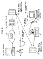
- FIG. 9 shows the constitution of a communication system adopting the communication control method according to the present invention.
- the communication system includes a portable telephone 33, a communication adapter (PC card) 31, a cable 32, a portable data terminal 30, a radio base station 34, mobile radio communication control stations 35 and 37, a home memory station 36, a gateway station 38, a telephone network 39 and a data terminal 40.
- the portable data terminal 30 is a notebook-type personal computer, for example.
- the portable telephone 33 and the portable data terminal 30 are connected to each other through the cable 32 and the communication adapter 31. More specifically, one end of the cable 32 is connected to the portable telephone 33, and the other end of the cable 32 is connected to the communication adapter 31 inserted in a card slot of the portable data terminal 30.
- This communication adapter 31 functions to modulate data outputted from the portable data terminal 30 into radio signals and demodulate radio signals received through the portable telephone 33.
- the portable data terminal 30 can perform data communication with the data terminal 40 through a communication network comprised of the portable telephone 33, the radio base station 34, the mobile radio communication control stations 35 and 37, the gateway station 38 and the telephone network 39.
- this communication system includes data terminals 1A and 1B, DCE (Data Circuit terminating Equipment) 4A, DCE 4B and a communication line 5.
- Figure 1 illustrates a situation where the data terminals 1A and 1B are connected to each other through the communication line 5 established in a network.
- the data terminal 1A is connected to the DCE 4A.
- the DCE 4A relays data between the data terminal 1A and the communication line 5.
- the data terminal 1B is connected to the DCE 4B.
- the DCE 4B relays data between the data terminal 1B and the communication line 5.
- the DCE 4A and DCE 4B are equivalent to the communication adapter 31 in the communication system shown in Figure 9.
- One data terminal can transmit data to and receive data from the other data terminal over a connection through the DCE 4A, the communication line 5 and the DCE 4B.
- the data terminal 1A has a communication module 3A and a communication control module 2A.
- the communication module 3A and the communication control module 2A are programs executed by a control part provided in the data terminal 1A. More specifically, the communication module 3A is a module for transmitting data to or receiving data from the data terminal 1B connected to the data terminal 1A through the communication line 5.
- the communication control module 2A is a module for controlling data communication performed by the communication module 3A.
- the data terminal 1B has a communication module 3B and a communication control module 2B similar to those in the data terminal 1A.
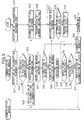
- Figure 2 illustrates operations for connecting the data terminal 1A to the data terminal 1B through the communication line 5.
- the communication module 3A in the data terminal 1A sends a connection request to the communication control module 2A (step S1).
- the communication control module 2A requests to the DCE 4A information on the present condition of the network (step S2).
- the DCE 4A diagnoses the present condition of the network (step S3).
- the DCE 4A diagnoses the condition of the network, based on control signals sent from the network. More specifically, the DCE 4A determines whether or not traffic congestion has occurred on the network, whether or not a trouble has occurred in the network, whether or not any line is available or the like.
- the DCE 4A also detects whether or not the portable telephone 33 is found within the wireless zone formed by the radio base station 34.
- the sending data terminal 1A is the portable data terminal as shown in Figure 9 that is connected to the network through the portable telephone 33
- the DCE 4A detects whether or not the portable telephone 33 is found within the wireless zone formed by the radio base station 34.
- the DCE 4A sends results of the detection (network information) to the communication control module 2A (step S4).
- the communication module 2A When the communication module 2A receives the network information (step S5), it analyzes it and judges, based on the network information, whether or not the present condition of the network is good (step S6). "The condition of the network is good" means that there are no problems with establishing a communication between the data terminals 1A and 1B. More specifically, the communication control module 2A determines that the condition of the network is good when the following are true:
- condition of the network is not good means that there is a problem with connecting the data terminal 1A to the data terminal 1B through the communication line 5. More specifically, the communication control module 2A determines that the condition of the network is not good when any one of the following is true:
- step S6 If the communication control module 2A determines in step S6 that the condition of the network is good, it sends a connection request to the DCE 4A (step S7).
- the communication control module 2A determines that the condition of the network is not good, it sends DCE 4A a directive to watch the condition of the network (step S8). In this step, the communication control module 2A does not inform the communication module 3A that there is a problem with establishing a communication.
- step S9 to S11 When the DCE 4A receives this directive, its operation mode switches over to a watching mode (steps S9 to S11). More specifically, this is done as follows;
- step S3 It has been detected in step S3 that the condition of the network is not good.
- the DCE 4A performs the same detection operation in step S9 and repeats the operation at regular intervals until it detects that the problem of the network has been cleared (steps S9 and S10). If the DCE 4A determines that the problem of the network is cleared, that is to say, if the condition of the network has turned good, the DCE 4A sends a watch result to the communication control module 2A (step S11). This watch result indicates that the condition of the network is now good.
- the communication control module 2A switches its operation mode to a waiting mode (steps S12 to S14) after the communication control module 2A sends the DCE 4A the directive to watch the condition of the network in Step 8. That is to say, the communication control module 2A waits for a fixed time (described below as "a waiting time") from the time when it sends the directive. If the communication control module 2A receives the watch result from the DCE 4A, that is to say, if the condition of the network turned good, before the waiting time lapses (step S13; Yes), it outputs a connection request to the DCE 4A (step S7).
- a waiting time a fixed time
- the communication control module 2A does not receive the watch result, that is to say, if the condition of the network does not turn good, within the waiting time (step S14; Yes), it informs the communication module 3A that it is impossible to establish the communication (step S16).
- the communication module 3A informs the user that it is impossible to establish the communication and ends the operations for data communication.
- the DCE 4A when the DCE 4A receives the connection request from the communication control module 2A in step S7, it forwards this connection request to the network (step S15).
- the communication control module 2B in the receiving data terminal 1B receives this circuit connect request through the network.
- the communication line 5 between the data terminals 1A and 1B is established after a series of operations such as a negotiation, an authentication and the like are performed.
- the communication module 3A in the data terminal 1A and the communication module 3B in the data terminal 1B transmit data to and receive data from each other through this communication line 5.
- an interruption response code is sent from the network to the data terminals 1A and 1B.
- the interruption response code includes information indicating the fact that the communication line is interrupted and the cause for the interruption.
- a possible cause for an interruption of a communication is as follows:
- the communication control module 2A in the data terminal 1A receives this interruption response code through the DCE 4A (steps S20 and S21). The communication control module 2A then judges, based on the interruption response code, whether or not it is possible to reestablish the interrupted communication (step S22). More specifically, if the cause of the interruption is such that the interruption is temporary, or the problem can be solved in a time, the communication control module 2A determines that it is possible to reestablish the communication.
- the communication control module 2A determines that it is possible to reestablish the communication it the interruption was caused by one of the following:
- the communication control module 2A determines that it is impossible to reestablish the communication.
- the communication control module 2A determines that it is impossible to reestablish the communication if the cause of the interruption is any one of the following;
- step S22 If the communication control module 2A determines in step S22 that it is impossible to reestablish the communication, it informs the communication module 3A that the communication line 5 is disconnected (step S23). When the communication module 3A receives this notification, it informs the user that the communication line is disconnected and ends the operations for the data communication between the data terminals 1A and 1B.
- the communication control module 2A determines that it is possible to reestablish the communication, it performs operations for reestablishing the interrupted communication without informing the communication module 3A of the interruption of the communication. More specifically, these operations are as follows:
- the communication control module 2A requests to the DCE 4A information on the condition of the network (step S24).
- the DCE 4A diagnoses the condition of the network (step S25) and sends results of the diagnosis (network information) to the communication module 2A (step S26).
- step S27 When the communication control module 2A receives the network information (step S27), it judges whether or not the present condition of the network is good (step S28). If the communication control module 2A determines that the condition of the network is good, it sends the DCE 4A a directive to perform a retransmission (step S29).
- step S30 the communication module 2A determines in step S28 that the condition of the network is not good, it sends the DCE 4A a directive to watch the condition of the network (step S30).
- step S31 to S33 When the DCE 4A receives this directive, its operation mode switches to a watching mode (steps S31 to S33). That is to say, the DCE 4A diagnoses the condition of the network at regular intervals. As a result of this diagnosis, if the DCE 4A determines that the problem that happened in the network has now been solved (step S32; Yes), it sends this watch result to the communication control module 2A (step S33). In contrast, if the problem in the network has not been solved, the DCE 4A repeats the same diagnosis at regular intervals (steps S31 and S32).
- step S30 when the communication control module 2A in step S30 sends the DCE 4A the directive to watch the condition of the network, its operation mode switches to a waiting mode, and it waits for the waiting time to lapse (steps S34 to S36). If the communication control module 2A receives the watch result before the waiting time elapses (step S35; Yes), that is to say, if the condition of the network has turned good, it outputs a connection request to the DCE 4A (step S29).
- the communication control module 2A does not receive the watch result from the DCE 4A before the waiting time elapses, that is to say, if the condition of the network would has not turned good (step S36; Yes), it informs the communication module 3A that the communication has been disconnected (step S37).
- the communication module 3A receives this notification, it informs the user that it is impossible to reestablish the communication and ends the operations for performing the data communication.
- connection request is sent from the communication control module 2A in step S29
- the DCE 4A forwards the connection request to the network (step S38).
- the communication control module 2B in the receiving data terminal 1B receives this connection request through the network. Thereafter, a series of operations such as a negotiation, an authentication of the sender and the like are performed, and the communication line 5 between the data terminals 1A and 1B is reestablished.
- the communication module 3A is not informed of the interruption of the communication in a case where it is possible to reestablish the communication. That is to say, since the communication module 3A does not recognize the interruption of the communication line 5, it will proceed to perform the same operation that has been halted since the communication circuit was interrupted. Therefore, when the communication is reestablished, the data communication will be restored retrospectively to the time of the interruption.
- FIG. 4 illustrates the constitution of a communication system adopting the communication control method according to the present invention.
- this communication system includes data terminals 1C and 1S which are, for instance, personal computers, DCE 4C, DCE 4S and the communication line 5.
- the data terminal 1C operates as a client.
- the data terminal 1S operates as a server which sends data in response to a request from the data terminal 1C operating as a client.
- the data terminal 1C is connected to the communication line 5 through the DCE 4C.
- the data terminal 1S is connected to the communication line 5 through the DCE 4S.
- the DCE 4C and DCE 4S are modems, for example.
- the data terminal 1C includes a communication application 61C, a TCP 62C, a PPP 63C, a communication port 7C and a port driver 8C.
- the communication application 61C is an application program executed by a control part provided in the data terminal 1C when data communication is performed between the data terminals 1C and 1S.
- the TCP 62C is a protocol that functions to receive from the communication application 61C data to be sent to the data terminal 1S, determine to which application in the receiving data terminal 1S the data should be sent and add to the data information on its determination.
- the PPP 63C is a protocol for establishing an IP connection through a public telephone network.
- the communication applications 61C, TCP 62C and PPP 63C are collectively indicated as "an upper application 6C". This upper application 6C is equivalent to the communication module 3A as shown in Figure 1.
- the DCE 4C is connected to the communication port 7C in the data terminal 1C.
- the port driver 8C functions to process signals outputted from the upper application 6C to the communication port 7C and signals inputted from the DCE 4C to the communication port 7C and to control data communication between the data terminals through the communication port 7C.
- the port driver 8C functions to reestablish the communication line 5 when the communication line 5 is interrupted (details are described later).
- This port driver 8C is equivalent to the communication control module 2A as shown in Figure 1.
- the server data terminal 1S includes an upper application 6S comprised of (a communication application 61S, TCP 62S and PPP 63S,) a communication port 7S and a port driver 8S.
- a user of the client data terminal 1C gives the communication application 61C a command to start a data communication, it outputs a connection request specifying the server data terminal 1S (step S40).
- the port driver 8C receives this connection request, it asks the DEC 4c about the condition of the network (step S41).
- the DCE 4C diagnoses the condition of the network in response to this inquiry.
- the DCE 4C sends a result of the diagnosis (network information) to the port driver 8C (step S42).
- the port driver 8C judges whether or not the condition of the network is good, based on the network information sent from the DCE 4C. If the port driver 8C determines that the condition of the network is good, it forwards the connection request to the network (step S43). At the same time, the port driver 8C writes a telephone number of the server in a memory provided in the data terminal 1C. This telephone number of the server is included in the connection request described above. In this embodiment, the telephone number of the server is written in the memory in step S44. Please note, however, that such information is not only the information to be written in the memory in step S44. That is to say, the information to be memorized in the memory may include information for use in specifying the server data terminal 1S, such as the name of the server and its IP address.
- the port driver 8S in the receiving data terminal 1S receives the connection request from the data terminal 1C through the network.
- the port driver 8S writes a telephone number of the client in a memory provided in the data terminal 1S (step S45). This telephone number of the client is included in the connection request.
- a series of operations for establishing a communication such as a negotiation and an authentication of the client, are performed by the DCE 4C and DCE 4S, and the data terminal 1C is thereafter connected to the data terminal 1S through the communication line 5 (step S46).
- an interruption response code is sent to the data terminals 1C and 1S from the network (steps S48 and S49).
- This interruption response code includes information indicating the fact that the communication has been interrupted and the cause for the interruption.
- the port driver 8S in the server data terminal 1S judges, based on the interruption response code received through the DCE 4S, whether or not it is possible to reestablish the communication line 5 (step S51). If the port driver 8S determines that it is possible to reestablish the communication, it waits, without informing the upper application 6S of the interruption of the communication, until a request for reestablishing the communication is sent from the data terminal 1C (step S53). On the other hand, if the port driver 8S determines in step S51 that it is impossible to reestablish the communication, it informs the upper application of the disconnection of the communication. As a result, the data communication is ended.
- the port driver 8C in the client data terminal 1C receives the interruption response code through the DCE 4C (step S48), it judges, based on this interruption response code, whether or not it is possible to reestablish the communication (step S50). If the port driver 8C determines that it is impossible to reestablish the communication, it informs the upper application 6C of the disconnection of the communication.
- the port driver 8C determines that it is possible to reestablish the communication, it asks the DCE 4C about the condition of the network (step S52). After this, the port driver 8C switches its operation mode to the waiting mode. The port driver 8C does not inform the upper application of the interruption of the communication circuit 5.
- the DCE 4C diagnoses the condition of the network in response to the inquiry from the port driver 8C as described above. As a result of this diagnosis, if the DCE 4C determines that the condition of the network has turned good, it sends the port driver 8C a watch result indicating that the condition of the network is now good (step S54).
- the port driver 8C When the port driver 8C receives this watch result, it reads the telephone number of the server memorized in step S44 and it sends a connection request to the data terminal 1S, which is identified by the read out telephone number (step S55).
- the port driver 8S in the data terminal 1S being in the waiting mode receives this request, it compares the telephone number of the sender memorized in step S45 with the telephone number notified this time (step S56). If both of the telephone numbers are the same, the port driver 8S in the data terminal 1S performs an off-hook operation (step S57). As a result, the communication between the data terminal 1C and the data terminal 1S is reestablished (step S58).
- the communication is reestablished without notifying the upper applications 6C and 6S of the interruption of the communication in a case where it is possible to reestablish the communication. That is to say, for the upper application 6C and the upper application 6S, the connection has been maintained. Therefore, when the communication is reestablished, the data communication is restored retrospectively to the time of the interruption of the communication.
- Figure 6A shows a situation where the client data terminal 1C is downloading files stored in a memory in the server data terminal 1S.
- Data outputted from the communication application 61S in the data terminal 1S is sent to the data terminal 1C by the PPP 63S and the TCP 62S during the course of the operation.
- This data is sent to the communication application 61C by the PPP 63C and the TCP 62C in the data terminal 1C.
- the communication application 61C writes data thus received in a memory provided in the data terminal 1C in order.
- Figure 6B shows a situation where the communication line 5 is interrupted for an unexpected cause while the data terminal 1C is downloading data from the data terminal 1S.
- an interruption response code indicating the interruption of the communication circuit is sent to the communication applications in the data terminals. As a result, the data communication between them is ended.
- Figure 6C shows a situation where the interrupted communication line 5 is reestablished. As described above, the operations for reestablishing the communication are performed only by the port driver 8C in the data terminal 1C and the port driver 8S in the data terminal 1S.
- the port driver 8S in the server data terminal 1S does not inform the upper application 6S, i.e., the TCP 62S, the PPP 63S and the like, that the communication line has been interrupted. More specifically, the TCP 62S in the data terminal 1S does not recognize the interruption of the communication. Therefore, as it was doing before the communication was interrupted, the TCP 62C, for example, requests the communication port 7S to send data. A signal indicating an acknowledgement (ACK), however, is not sent back to the TCP 62S in response to the above request because the communication has been interrupted. As a result, until informed by the port driver 8S of a reestablishment or a disconnection of the communication, the upper application 6S repeats the operations to try to send the data that it was sending when the communication was interrupted.
- the TCP 62S i.e., the TCP 62S, the PPP 63S and the like
- the port driver 8C in the client data terminal 1C does not inform the upper application 6C that the communication has been interrupted.
- the TCP 62C and others repeat the same receiving operations that it was performing when the communication was interrupted.
- Figure 6D shows a situation after the reestablishing of the communication is completed.
- the data terminal 1S starts sending data to the data terminal 1C again.
- the upper application 6S in the data terminal 1S repeated the same sending operations that it had been performing at the time of the interruption.
- the upper application 6S starts sending the data that remained to be sent at the time of the interruption.
- the upper application 6C in the data terminal 1C repeated the same receiving operations that it had been performing at the time of the interruption.
- the upper application 6C starts receiving the data that remained to be received at the time of the interruption. That is to say, the communication can be restored retrospectively to the time of the interruption of the communication line 5.
- this embodiment even if a communication is interrupted while the client data terminal is downloading data, a user of the data terminal does not need to start the same operations for downloading the data allover again from the beginning.
- this embodiment has an advantage of reducing a communication time and a communication charge.
- a facsimile transmits image data to or receives image data from another facsimile.
- this communication system includes facsimiles 10A and 10B and the communication line 5, which connects the facsimile 10A and the facsimile 10B.
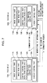
- the facsimile 10A includes an image outputting part 11A, an image reading part 12A, a central control part 13A, a FAX protocol control part 14A and a communication control part 15A.
- the image outputting part 11A receives from the central control part 13A image data sent from another facsimile and prints out this image data on a paper.
- the image read part 12A reads an image printed on a paper as an object of transmission by means of a CCD sensor and outputs the image data to the central control part 13A.
- the central control part 13A includes a CPU, a RAM and a ROM, and functions as a central controlling means. More specifically, the central control part 13A outputs to the image output part 11A image data sent from another facsimile through the communication line 5.
- the central control part 13A sends the image data from the image read part 12A to another facsimile through the communication line 5.
- the FAX protocol control part 14A functions to control an image transmission protocol in the facsimile 10A.
- the FAX protocol control part 14A, the central control part 13A, the image reading part 12A and the image outputting part 11A are collectively indicated as an upper application. This upper application is equivalent to the communication module 3A as shown in Figure 1.
- the communication control part 15A controls establishing or reestablishing of the communication line 5 between the facsimile 10A and the other facsimile 10B.
- This communication control part 15A is equivalent to the communication control module 2A as shown in Figure 1.
- the configuration of the facsimile 10B is similar to the configuration of the facsimile 10A. That is to say, the facsimile 10B includes an image outputting part 11B, an image reading part 12B, a central control part 13B, a FAX protocol control part 14B and a communication control part 15B. Because the functions of these parts are similar to those of the corresponding parts in the facsimile 10A, their explanations are omitted.
- the communication control part 15A sends a connection request to the facsimile 10B.
- the communication control part 15B in the facsimile 10B receives this request, it writes ID information of the sender in a memory provided in the facsimile 10B (as shown by "A" in Figure 7).
- the facsimile 10A is connected to the facsimile 10B through the communication line 5 after a series of operations such as a negotiation, an authentication and the like, are performed.
- an interruption response code such as "NO_CARRIER" is sent from the network to the communication control part 15A in the facsimile 10A and the communication control part 15B in the facsimile 15B (as shown by "B” in Figure 7).
- the communication control part 15B in the receiving facsimile 10B judges, based on the informed interruption response code, whether or not it is possible to reestablish the communication. If the communication control part 15B determines that it is possible to reestablish the communication, it starts waiting for a transmission from the sending facsimile 10A without informing the upper application of the interruption of the communication line 5 (as shown by "C" in Figure 7). Likewise, the communication control part 15A in the sending facsimile 10A judges whether or not it is possible to reestablish the communication line. If the communication control part 15A determines that it is possible to reestablish the communication, it diagnoses the condition of the network.
- the communication control part 15A determines that the condition of the network has turned good, it sends a connection request to the facsimile 10B (as shown by "D” in Figure 7).
- the communication control part 15B in the facsimile 10B receives this request (as shown by "E” in Figure 7), it compares the ID information of the sender included in this connection request with the ID information stored at the time of the first connection of the communication line (as shown by "F” in Figure 7). If both of them are the same, the communication control part 15B performs the operations for reestablishing the communication line 5.
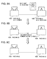
- Figure 8A shows a situation where the facsimile 10A is sending image data representing a letter "A" to the facsimile 10B.
- the central control part 13A in the sending facsimile 10A repeatedly outputs the image data that remains to be sent at the time of the interruption of the communication line 5.
- the central control part 13B also repeats the same operation that it was performing at the time of the interruption.
- the sending facsimile 10A starts sending the image data that remained to be sent at the time of the interruption.
- the facsimile 10B starts receiving the image data that remained to be received at the time of the interruption. That is to say, the communication can be restored retrospectively to the time of the interruption of the communication.
- the following describes a communication system using the communication control method according to the present invention.
- data communication can be performed through portable telephones.
- this communication system includes a portable telephone 33, a communication adapter (PC card) 31, a cable 32, a portable data terminal 30, a radio base station 34, mobile radio communication control stations 35 and 37, a home memory station 36, a gateway station 38, a telephone network 39 and a data terminal 40.
- the portable data terminal 30 is a notebook-type personal computer, for example.
- Each of the portable data terminal 30 and the data terminal 40 includes the upper application 61 comprised of the communication application 61, the TCP 62 and PPP 63, the communication port 7 and the port driver 8, such as those provided in the data terminals 1C and 1S shown in Figure 4.
- the portable data terminal 30 is connected with the portable telephone 33 through the cable 32 and the communication adapter 31.
- one end of the cable 32 is connected to the portable telephone 33.
- the other end of the cable 32 is connected to the communication adapter 31, which is inserted in a card slot of the portable data terminal 30 and connected to the communication port 7.
- This communication adapter 31 functions as a modem to convert into radio signals data outputted from the portable data terminal 30.
- the portable data terminal 30 can transmit data to or receive data from the data terminal 40 through the communication network formed from the portable telephone 33, the radio base station 34, the mobile radio communication control stations 35 and 37, the gateway station 38 and the telephone network 39.
- the home memory station 36 has a database storing information regarding the present location of the portable telephone 33.
- the portable data terminal 30 sends data to the data terminal 40.
- the communication application 61 in the portable data terminal 30 outputs a connection request.
- the portable telephone 33 sends this connection request to the radio base station 34, which form a wireless zone in which the portable telephone 33 is located.
- This connection request is sent to the data terminal 40 through the mobile radio communication control stations 35 and 37, the gateway station 38, the telephone network 39 and the like.
- a series of operations including a negotiation, an authentication and the like are performed, and a communication between the portable data terminal 30 and the data terminal 40 is established.
- Figure 10 illustrates operations that are performed in the communication system according to this embodiment when a communication is interrupted for an unexpected cause.
- the communication adapter 31 sends to the port driver 8 in the portable data terminal 30 an interruption response code including notification of the fact that the communication has been interrupted and the cause for the interruption.
- the port driver 8 judges, based on this interruption response code (step S60), whether or not it is possible to reestablish the communication (step S61).
- the port driver 8 in the portable data terminal 30 determines that it is impossible to reestablish the communication, it informs the upper application of the disconnection of the communication. Thereafter, the data communication between the portable data terminal 30 and the data terminal 40 ends (step S69).
- the port driver 8 determines that it is possible to reestablish the communication, it performs operations for reestablishing the communication without informing the upper application of the interruption of the communication. That is to say, these operations are as follows.
- the port driver 8 sends to the communication adapter 31 an AT command to inquire the current condition of the portable telephone 33 (step S62).
- the communication adapter 31 sends to the port driver 8 a response code indicating whether or not the portable telephone 33 is within the wireless zone formed by the radio base station 34.
- the port driver 8 analyzes this response code (step S63), and it judges whether or not the portable telephone 33 is within the wireless zone (step S64). If the port driver determines that the portable telephone 33 is within the wireless zone, it sends a connection request to the communication adapter 31 (step S67).
- the port driver 8 determines in step S64 that the portable telephone 33 is not within the wireless zone, it starts counting a waiting time. In addition, the port driver 8 repeatedly sends at regular intervals the AT command for inquiring the condition of the portable telephone 33. In response to the AT command sent from the port driver 8, the communication adapter 31 returns to the port driver 8 the response code indicating whether or not the portable telephone 33 is currently within the wireless zone.
- the port driver 8 If the port driver 8 receives the response code indicating that the portable telephone 33 moves within the wireless zone before the port driver 8 counts up to the waiting time (steps S65 and S66; Yes), the port driver 8 sends the connection request to the communication adapter 31 (step S67).
- step S68 if the port driver 8 does not receive the response code indicating that the portable telephone 33 moves within the wireless zone before the port driver 8 counts up to the waiting time (step S68; Yes), the port driver 8 informs the upper application of the disconnection of the communication. As a result, the operations for the data communication between the portable data terminal 30 and the data terminal 40 are ended (step S69).
- connection request is sent from the port driver 8 in step S67
- the communication adapter 31 forwards this connection request to the data terminal 40.
- the communication between the portable data terminal 30 and the data terminal 40 is thereby reestablished.
- the same effects as the first preferred embodiment described above can be obtained.
- the judgment as to whether to reestablish a communication is made based on whether or not the portable telephone 33 is within the wireless zone. Therefore, it is possible to eliminate the execution of the unnecessary operations in which a transmission for reestablishing the communication is repeated despite the fact that the portable telephone is not within the wireless zone.
- the AT command is used for inquiring the condition of a portable telephone, but other kinds of command may of curse be used instead of the AT command.
- the communication control program is recorded on the floppy disk, but a storage medium for storing this program is not limited to a floppy disk. Of course, various kinds of recording medium such as a CD-ROM may be available for storing the program.
Landscapes
- Engineering & Computer Science (AREA)
- Computer Networks & Wireless Communication (AREA)
- Signal Processing (AREA)
- Computer Security & Cryptography (AREA)
- Communication Control (AREA)
- Telephonic Communication Services (AREA)
- Mobile Radio Communication Systems (AREA)
- Computer And Data Communications (AREA)
- Maintenance And Management Of Digital Transmission (AREA)
Abstract
Description
Claims (17)
- A communication control method for a data terminal which includes data communication module for transmitting data to or receiving data from another data terminal connected with the data terminal through a communication line, the method comprising the steps of:detecting an interruption of the communication line; andwhen it is detected that the communication line is interrupted, reestablishing the communication line without informing the data communication module of the interruption of the communication line.
- A communication control method according to claim 1 further comprising the step of judging whether to reestablish the interrupted communication line, wherein when it is detected that the communication line is interrupted, and it is judged that the communication line should be reestablished, the communication line is reestablished without informing the data communication module of the interruption of the communication line.
- A communication control method according to claim 2, wherein it is judged, based on a cause for the interruption of the communication line, whether to reestablish the communication line.
- A communication control method according to claim 2 further comprising the step of diagnosing the condition of a network, wherein it is judged, based on the diagnosed condition of the network, whether to reestablish the communication line.
- A communication control method according to claim 3 further comprising the step of diagnosing the condition of a network, wherein it is judged, based on the cause for the interruption of the communication line and the diagnosed condition of the network, whether to reestablish the communication line.
- A communication control apparatus for controlling a data terminal with a data communication module for performing a data communication with another data terminal, the communication control apparatus comprising:a detector for detecting an interruption of the communication line; anda communication controller for reestablishing, when the detector detects an interruption of the communication line, the communication line without informing the data communication module of the interruption of the communication line.
- A communication control apparatus according to claim 6 further comprising a judging module for judging whether to reestablish the interrupted communication line, wherein when the detector detects an interruption of the communication line, and the judging module determines that the communication line should be reestablished, the communication controller reestablishes the interrupted communication line without informing the data communication module of the interruption of the communication line.
- A communication control apparatus according to claim 7, wherein the judging module judges, based on a cause for the interruption of the communication line, whether to reestablish the interrupted communication line.
- A communication control apparatus according to claim 7 further comprising a diagnosing module for diagnosing the condition of a network, wherein the judging module judges, based on the diagnosed condition of the network, whether to reestablish the interrupted communication line.
- A communication control apparatus according to claim 8 further comprising a diagnosing module for diagnosing the condition of a network, wherein the judging module judges, based on the cause for the interruption of the communication circuit and the diagnosed condition of the network, whether to reestablish the interrupted communication line.
- A communication control apparatus according to claim 9, whereinthe data communication module performs data communication through a portable terminal which wirelessly communicates with a radio base station,the diagnosing module determines whether or not the portable terminal is within a wireless zone formed by the radio base station, andthe judging module judges, based on whether or not the portable terminal is within the wireless zone, whether to reestablish the interrupted communication line.
- A communication control apparatus according to claim 7 further comprising an inquiring module for sending an inquiry as to the condition of the network to an external diagnosing module for diagnosing the condition of the network, wherein the judging module judges, based on the condition of the network diagnosed by the external diagnosing module, whether to reestablish the interrupted communication line.
- A storage medium that stores a communication control program executed by a data terminal which includes data communication module for performing data communication with another data terminal through a communication line, the program comprising the steps of:detecting an interruption of the communication line;when it is detected that the communication line is interrupted, reestablishing the communication line without informing the data communication module of the interruption of the communication line.
- A storage medium that stores a communication control program according to claim 13, the program further comprising the step of judging whether to reestablish the interrupted communication line, wherein when it is detected that the communication line is interrupted, and it is judged that the communication line should be reestablished, the communication line is reestablished without informing the data communication module of the interruption of the communication line.
- A storage medium that stores a communication control program according to claim 14, wherein it is judged, based on a cause for the interruption of the communication line, whether to reestablish the communication line.
- A storage medium that stores a communication control program according to claim 14, the program further comprising the step of diagnosing the condition of a network, wherein it is judged, based on the diagnosed condition of the network, whether to reestablish the communication line.
- A storage medium that stores a communication control program according to claim 15, the program further comprising the step of diagnosing the condition of a network, wherein it is judged, based on the cause for the interruption of the communication line and the diagnosed condition of the network, whether to reestablish the communication line.
Applications Claiming Priority (3)
| Application Number | Priority Date | Filing Date | Title |
|---|---|---|---|
| JP32260598 | 1998-11-12 | ||
| JP32260598A JP3223355B2 (en) | 1998-11-12 | 1998-11-12 | Communication control method, communication control device, recording medium, and data terminal |
| PCT/JP1999/006333 WO2000030303A1 (en) | 1998-11-12 | 1999-11-12 | Method and apparatus for communication control, and recording medium |
Publications (3)
| Publication Number | Publication Date |
|---|---|
| EP1054535A1 true EP1054535A1 (en) | 2000-11-22 |
| EP1054535A4 EP1054535A4 (en) | 2005-01-12 |
| EP1054535B1 EP1054535B1 (en) | 2006-07-26 |
Family
ID=18145586
Family Applications (1)
| Application Number | Title | Priority Date | Filing Date |
|---|---|---|---|
| EP19990972394 Expired - Lifetime EP1054535B1 (en) | 1998-11-12 | 1999-11-12 | Method and apparatus for communication control, and recording medium |
Country Status (6)
| Country | Link |
|---|---|
| US (2) | US7003568B1 (en) |
| EP (1) | EP1054535B1 (en) |
| JP (1) | JP3223355B2 (en) |
| CN (1) | CN1319346C (en) |
| DE (1) | DE69932502T2 (en) |
| WO (1) | WO2000030303A1 (en) |
Cited By (1)
| Publication number | Priority date | Publication date | Assignee | Title |
|---|---|---|---|---|
| WO2003044618A3 (en) * | 2001-11-22 | 2003-10-30 | Sk Telecom Co Ltd | Method for connecting to a wireless internet service |
Families Citing this family (29)
| Publication number | Priority date | Publication date | Assignee | Title |
|---|---|---|---|---|
| JP3223355B2 (en) * | 1998-11-12 | 2001-10-29 | 株式会社エヌ・ティ・ティ・ドコモ | Communication control method, communication control device, recording medium, and data terminal |
| JP3492602B2 (en) | 2000-07-07 | 2004-02-03 | 松下電器産業株式会社 | Data transmitting device and data receiving device |
| GB2366914B (en) * | 2000-09-13 | 2002-07-31 | Inventec Corp | Antenna apparatus for portable electronic device |
| JP4502487B2 (en) * | 2000-09-21 | 2010-07-14 | 三洋電機株式会社 | Mobile terminal device |
| JP2002152821A (en) | 2000-11-08 | 2002-05-24 | Nec Saitama Ltd | Program update method for mobile terminal and the mobile terminal |
| EP1351217A4 (en) * | 2001-01-12 | 2005-08-03 | Matsushita Electric Industrial Co Ltd | COMPOSED WITH MUSIC DISTRIBUTION COMPATIBLE PORTABLE END UNIT AND PORTABLE TERMINAL |
| JP2002368778A (en) * | 2001-06-12 | 2002-12-20 | Sony Corp | Communication terminal reconnection method and communication terminal |
| US7366776B2 (en) * | 2001-11-20 | 2008-04-29 | Sharp Laboratories Of America, Inc. | System and method for reestablishing a communication period in a rendezvous scheduled system |
| US8417795B1 (en) * | 2002-07-01 | 2013-04-09 | Horizon Technology Funding Company V Llc | Methods, systems, and computer program products for provisioning service between a network access device and a network interface unit |
| US7912899B2 (en) * | 2002-09-06 | 2011-03-22 | Oracle International Corporation | Method for selectively sending a notification to an instant messaging device |
| US7899879B2 (en) | 2002-09-06 | 2011-03-01 | Oracle International Corporation | Method and apparatus for a report cache in a near real-time business intelligence system |
| US7945846B2 (en) * | 2002-09-06 | 2011-05-17 | Oracle International Corporation | Application-specific personalization for data display |
| US8255454B2 (en) | 2002-09-06 | 2012-08-28 | Oracle International Corporation | Method and apparatus for a multiplexed active data window in a near real-time business intelligence system |
| US7941542B2 (en) * | 2002-09-06 | 2011-05-10 | Oracle International Corporation | Methods and apparatus for maintaining application execution over an intermittent network connection |
| US7412481B2 (en) | 2002-09-16 | 2008-08-12 | Oracle International Corporation | Method and apparatus for distributed rule evaluation in a near real-time business intelligence system |
| US8165993B2 (en) * | 2002-09-06 | 2012-04-24 | Oracle International Corporation | Business intelligence system with interface that provides for immediate user action |
| US7668917B2 (en) * | 2002-09-16 | 2010-02-23 | Oracle International Corporation | Method and apparatus for ensuring accountability in the examination of a set of data elements by a user |
| US7401158B2 (en) * | 2002-09-16 | 2008-07-15 | Oracle International Corporation | Apparatus and method for instant messaging collaboration |
| US7904823B2 (en) * | 2003-03-17 | 2011-03-08 | Oracle International Corporation | Transparent windows methods and apparatus therefor |
| KR100585724B1 (en) * | 2003-08-18 | 2006-06-07 | 엘지전자 주식회사 | Network State Notification Service Method for General Packet Radio Service System |
| US20090252072A1 (en) * | 2008-04-08 | 2009-10-08 | Telefonaktiebolaget Lm Ericsson (Publ) | Method and Apparatus for Maintaining Long-Lived Connections Between a Mobile Client and a Server |
| US8306097B2 (en) * | 2008-06-04 | 2012-11-06 | Alcatel Lucent | Signal suspension and resumption in DSL systems |
| CN101340671B (en) * | 2008-08-07 | 2011-12-28 | 北京天碁科技有限公司 | Inquiry method and system for AT command |
| JP4945528B2 (en) * | 2008-08-21 | 2012-06-06 | 株式会社東芝 | Display device, communication method, and communication program |
| JP5004921B2 (en) * | 2008-10-28 | 2012-08-22 | キヤノン株式会社 | Communication apparatus and communication control method |
| CN102566527B (en) * | 2010-12-30 | 2015-06-10 | 中国科学院沈阳自动化研究所 | Method for realizing transmission control platformization of semiconductor manufacturing equipment front end module |
| JP7243479B2 (en) * | 2019-06-24 | 2023-03-22 | ブラザー工業株式会社 | A server, a computer program for a server, and a computer program for a terminal device |
| CN111042970B (en) * | 2019-12-11 | 2021-11-30 | 浙江锋锐发动机有限公司 | Vehicle cold start control method and device |
| CN118521326A (en) * | 2024-07-23 | 2024-08-20 | 山东农业工程学院 | Beef food safety traceability management system |
Family Cites Families (38)
| Publication number | Priority date | Publication date | Assignee | Title |
|---|---|---|---|---|
| JPH02186743A (en) * | 1989-01-13 | 1990-07-23 | Nec Eng Ltd | Call resetting system in packet exchange |
| JP2820155B2 (en) | 1989-07-20 | 1998-11-05 | 株式会社リコー | Control method of data terminal device |
| JP3139070B2 (en) | 1990-08-09 | 2001-02-26 | 富士ゼロックス株式会社 | Communication terminal device |
| JPH04102152A (en) | 1990-08-21 | 1992-04-03 | Mitsubishi Electric Corp | Virtual line communication system |
| EP0514360B1 (en) * | 1991-04-17 | 1998-06-17 | Telefonaktiebolaget L M Ericsson | A cellular communication system with integrated paging system |
| ES2162659T3 (en) * | 1992-06-12 | 2002-01-01 | Dow Chemical Co | COMMUNICATION SYSTEM HEAD-COLA SAFE AND METHOD FOR THE PROCEDURE IN COMPUTERS CONTROL. |
| JPH06284466A (en) * | 1993-03-26 | 1994-10-07 | Mitsubishi Electric Corp | Mobile radio telephone communication device |
| JPH07273762A (en) * | 1994-03-29 | 1995-10-20 | Oki Electric Ind Co Ltd | Communication equipment |
| US5566225A (en) * | 1994-11-21 | 1996-10-15 | Lucent Technologies Inc. | Wireless data communications system for detecting a disabled condition and simulating a functioning mode in response to detection |
| JPH08331647A (en) * | 1995-06-01 | 1996-12-13 | Nec Corp | Phs control method and system therefor |
| JPH08249255A (en) | 1995-03-15 | 1996-09-27 | Fujitsu Ltd | Information and communication service system |
| US5761507A (en) * | 1996-03-05 | 1998-06-02 | International Business Machines Corporation | Client/server architecture supporting concurrent servers within a server with a transaction manager providing server/connection decoupling |
| JP3205252B2 (en) | 1996-04-24 | 2001-09-04 | シャープ株式会社 | Mobile wireless terminal |
| US5896444A (en) * | 1996-06-03 | 1999-04-20 | Webtv Networks, Inc. | Method and apparatus for managing communications between a client and a server in a network |
| JP3392302B2 (en) * | 1996-10-04 | 2003-03-31 | 株式会社日立製作所 | Information processing apparatus, communication method, and storage medium |
| US5854897A (en) * | 1996-12-27 | 1998-12-29 | Quantum Systems, Inc. | Network communications marketing system |
| JPH10210546A (en) * | 1997-01-17 | 1998-08-07 | Sony Corp | Wireless communication system, fixed station device, and mobile station device |
| US5983259A (en) * | 1997-02-19 | 1999-11-09 | International Business Machines Corp. | Systems and methods for transmitting and receiving data in connection with a communications stack in a communications system |
| JPH10243053A (en) * | 1997-02-28 | 1998-09-11 | Nec Telecom Syst Ltd | Radio data communication equipment with re-connection mechanism |
| JP3105814B2 (en) * | 1997-03-06 | 2000-11-06 | 静岡日本電気株式会社 | Mobile communication system and terminal device thereof |
| US5987621A (en) * | 1997-04-25 | 1999-11-16 | Emc Corporation | Hardware and software failover services for a file server |
| US6292905B1 (en) * | 1997-05-13 | 2001-09-18 | Micron Technology, Inc. | Method for providing a fault tolerant network using distributed server processes to remap clustered network resources to other servers during server failure |
| US6314525B1 (en) * | 1997-05-13 | 2001-11-06 | 3Com Corporation | Means for allowing two or more network interface controller cards to appear as one card to an operating system |
| US6208616B1 (en) * | 1997-05-13 | 2001-03-27 | 3Com Corporation | System for detecting errors in a network |
| US6253334B1 (en) * | 1997-05-13 | 2001-06-26 | Micron Electronics, Inc. | Three bus server architecture with a legacy PCI bus and mirrored I/O PCI buses |
| US5944831A (en) * | 1997-06-13 | 1999-08-31 | Dell Usa, L.P. | Power management apparatus and method for managing power application to individual circuit cards |
| JP3019061B2 (en) * | 1997-06-27 | 2000-03-13 | 日本電気株式会社 | Mobile communication system and radio channel control method therefor |
| US6070191A (en) * | 1997-10-17 | 2000-05-30 | Lucent Technologies Inc. | Data distribution techniques for load-balanced fault-tolerant web access |
| JP3070561B2 (en) * | 1997-12-19 | 2000-07-31 | 日本電気株式会社 | Communication system using public line |
| JPH11275110A (en) * | 1998-03-26 | 1999-10-08 | Nec Corp | Wireless data communication method and apparatus |
| US6208718B1 (en) * | 1998-07-29 | 2001-03-27 | Lucent Technologies Inc. | Emergency interrupt technique |
| JP3012614B1 (en) * | 1998-10-16 | 2000-02-28 | 静岡日本電気株式会社 | Mobile communication system, mobile terminal used therefor, and reconnection method |
| JP3223355B2 (en) * | 1998-11-12 | 2001-10-29 | 株式会社エヌ・ティ・ティ・ドコモ | Communication control method, communication control device, recording medium, and data terminal |
| US6388990B1 (en) * | 1998-12-18 | 2002-05-14 | Covad Communications Company | Method and system for reducing congestion in connection-oriented packet networks having digital subscriber line access |
| US6507863B2 (en) * | 1999-01-27 | 2003-01-14 | International Business Machines Corporation | Dynamic multicast routing facility for a distributed computing environment |
| SG87029A1 (en) * | 1999-05-08 | 2002-03-19 | Kent Ridge Digital Labs | Dynamically delayed acknowledgement transmission system |
| US7020717B1 (en) * | 1999-09-29 | 2006-03-28 | Harris-Exigent, Inc. | System and method for resynchronizing interprocess communications connection between consumer and publisher applications by using a shared state memory among message topic server and message routers |
| JP4588271B2 (en) * | 2001-09-18 | 2010-11-24 | 富士通株式会社 | Data synchronization system, data synchronization method, data center, and client terminal |
-
1998
- 1998-11-12 JP JP32260598A patent/JP3223355B2/en not_active Expired - Lifetime
-
1999
- 1999-11-12 WO PCT/JP1999/006333 patent/WO2000030303A1/en not_active Ceased
- 1999-11-12 DE DE1999632502 patent/DE69932502T2/en not_active Expired - Lifetime
- 1999-11-12 CN CNB998021032A patent/CN1319346C/en not_active Expired - Lifetime
- 1999-11-12 US US09/581,632 patent/US7003568B1/en not_active Expired - Lifetime
- 1999-11-12 EP EP19990972394 patent/EP1054535B1/en not_active Expired - Lifetime
-
2005
- 2005-11-21 US US11/284,777 patent/US7627676B2/en not_active Expired - Fee Related
Cited By (2)
| Publication number | Priority date | Publication date | Assignee | Title |
|---|---|---|---|---|
| WO2003044618A3 (en) * | 2001-11-22 | 2003-10-30 | Sk Telecom Co Ltd | Method for connecting to a wireless internet service |
| RU2276473C2 (en) * | 2001-11-22 | 2006-05-10 | Ск Телеком Ко., Лтд. | Method for connecting to wireless service of internet network |
Also Published As
| Publication number | Publication date |
|---|---|
| EP1054535A4 (en) | 2005-01-12 |
| CN1288623A (en) | 2001-03-21 |
| JP3223355B2 (en) | 2001-10-29 |
| US7627676B2 (en) | 2009-12-01 |
| JP2000151749A (en) | 2000-05-30 |
| US20060161649A1 (en) | 2006-07-20 |
| CN1319346C (en) | 2007-05-30 |
| DE69932502D1 (en) | 2006-09-07 |
| WO2000030303A1 (en) | 2000-05-25 |
| DE69932502T2 (en) | 2007-02-22 |
| US7003568B1 (en) | 2006-02-21 |
| EP1054535B1 (en) | 2006-07-26 |
Similar Documents
| Publication | Publication Date | Title |
|---|---|---|
| US7627676B2 (en) | Communication control method, communication control apparatus and storage medium | |
| US7477880B2 (en) | Communication device, image-pickup device, storage medium and communication method | |
| JP2001522168A (en) | Wireless local area network transferring information by a given link agent | |
| KR20050118736A (en) | Information processing apparatus and connection control method | |
| US6594485B1 (en) | Mobile terminal, communication system for the same and method of re-connection in the same | |
| EP0892547B1 (en) | Communication apparatus | |
| JPH11127328A (en) | Communication device | |
| US6873859B2 (en) | Method for sevicing facsimile using wireless local loop system | |
| US6307642B1 (en) | Communication apparatus | |
| JP3269423B2 (en) | Communication terminal device with automatic program update function and recording medium readable by this device | |
| US6965570B2 (en) | Communication controller and computer product | |
| JP3037261B2 (en) | Mobile phone communication switching method | |
| JP3608648B2 (en) | Wireless communication system | |
| WO2004040887A2 (en) | Digital radio communications apparatus | |
| JP3707036B2 (en) | Communication control method between facsimile apparatus and facsimile | |
| KR100271453B1 (en) | Method for communicating in mobile communication system | |
| JPH08265497A (en) | Facsimile system | |
| JP2971936B2 (en) | Data communication method | |
| JPH10117254A (en) | Multi-function device | |
| JP3314739B2 (en) | Facsimile machine | |
| US6452697B2 (en) | Facsimile apparatus, line control board and communication control method | |
| JP2934021B2 (en) | Data relay transmission device, data transmission system, and data transmission method | |
| JP3386617B2 (en) | Portable facsimile machine | |
| JP2001094624A (en) | Protocol conversion device and communication system using the same | |
| JP2000332975A (en) | Facsimile machine |
Legal Events
| Date | Code | Title | Description |
|---|---|---|---|
| PUAI | Public reference made under article 153(3) epc to a published international application that has entered the european phase |
Free format text: ORIGINAL CODE: 0009012 |
|
| 17P | Request for examination filed |
Effective date: 20000711 |
|
| AK | Designated contracting states |
Kind code of ref document: A1 Designated state(s): DE FR GB IT SE |
|
| A4 | Supplementary search report drawn up and despatched |
Effective date: 20041126 |
|
| 17Q | First examination report despatched |
Effective date: 20050310 |
|
| GRAP | Despatch of communication of intention to grant a patent |
Free format text: ORIGINAL CODE: EPIDOSNIGR1 |
|
| GRAS | Grant fee paid |
Free format text: ORIGINAL CODE: EPIDOSNIGR3 |
|
| GRAA | (expected) grant |
Free format text: ORIGINAL CODE: 0009210 |
|
| AK | Designated contracting states |
Kind code of ref document: B1 Designated state(s): DE FR GB IT SE |
|
| PG25 | Lapsed in a contracting state [announced via postgrant information from national office to epo] |
Ref country code: IT Free format text: LAPSE BECAUSE OF FAILURE TO SUBMIT A TRANSLATION OF THE DESCRIPTION OR TO PAY THE FEE WITHIN THE PRE;WARNING: LAPSES OF ITALIAN PATENTS WITH EFFECTIVE DATE BEFORE 2007 MAY HAVE OCCURRED AT ANY TIME BEFORE 2007. THE CORRECT EFFECTIVE DATE MAY BE DIFFERENT FROM THE ONE RECORDED.SCRIBED TIME-LIMIT Effective date: 20060726 |
|
| REG | Reference to a national code |
Ref country code: GB Ref legal event code: FG4D |
|
| REF | Corresponds to: |
Ref document number: 69932502 Country of ref document: DE Date of ref document: 20060907 Kind code of ref document: P |
|
| REG | Reference to a national code |
Ref country code: SE Ref legal event code: TRGR |
|
| ET | Fr: translation filed | ||
| PLBE | No opposition filed within time limit |
Free format text: ORIGINAL CODE: 0009261 |
|
| STAA | Information on the status of an ep patent application or granted ep patent |
Free format text: STATUS: NO OPPOSITION FILED WITHIN TIME LIMIT |
|
| 26N | No opposition filed |
Effective date: 20070427 |
|
| REG | Reference to a national code |
Ref country code: FR Ref legal event code: PLFP Year of fee payment: 17 |
|
| REG | Reference to a national code |
Ref country code: FR Ref legal event code: PLFP Year of fee payment: 18 |
|
| REG | Reference to a national code |
Ref country code: FR Ref legal event code: PLFP Year of fee payment: 19 |
|
| REG | Reference to a national code |
Ref country code: FR Ref legal event code: PLFP Year of fee payment: 20 |
|
| PGFP | Annual fee paid to national office [announced via postgrant information from national office to epo] |
Ref country code: DE Payment date: 20181030 Year of fee payment: 20 Ref country code: SE Payment date: 20181113 Year of fee payment: 20 |
|
| PGFP | Annual fee paid to national office [announced via postgrant information from national office to epo] |
Ref country code: GB Payment date: 20181107 Year of fee payment: 20 Ref country code: FR Payment date: 20181011 Year of fee payment: 20 Ref country code: IT Payment date: 20181122 Year of fee payment: 20 |
|
| REG | Reference to a national code |
Ref country code: DE Ref legal event code: R071 Ref document number: 69932502 Country of ref document: DE |
|
| REG | Reference to a national code |
Ref country code: GB Ref legal event code: PE20 Expiry date: 20191111 |
|
| PG25 | Lapsed in a contracting state [announced via postgrant information from national office to epo] |
Ref country code: GB Free format text: LAPSE BECAUSE OF EXPIRATION OF PROTECTION Effective date: 20191111 |
|
| REG | Reference to a national code |
Ref country code: SE Ref legal event code: EUG |