EP1054396A2 - Tape apparatus mechanism - Google Patents
Tape apparatus mechanism Download PDFInfo
- Publication number
- EP1054396A2 EP1054396A2 EP00304193A EP00304193A EP1054396A2 EP 1054396 A2 EP1054396 A2 EP 1054396A2 EP 00304193 A EP00304193 A EP 00304193A EP 00304193 A EP00304193 A EP 00304193A EP 1054396 A2 EP1054396 A2 EP 1054396A2
- Authority
- EP
- European Patent Office
- Prior art keywords
- cartridge
- loader
- drive
- threader
- engaged
- Prior art date
- Legal status (The legal status is an assumption and is not a legal conclusion. Google has not performed a legal analysis and makes no representation as to the accuracy of the status listed.)
- Granted
Links
Images





Classifications
-
- G—PHYSICS
- G11—INFORMATION STORAGE
- G11B—INFORMATION STORAGE BASED ON RELATIVE MOVEMENT BETWEEN RECORD CARRIER AND TRANSDUCER
- G11B15/00—Driving, starting or stopping record carriers of filamentary or web form; Driving both such record carriers and heads; Guiding such record carriers or containers therefor; Control thereof; Control of operating function
- G11B15/60—Guiding record carrier
- G11B15/66—Threading; Loading; Automatic self-loading
- G11B15/67—Threading; Loading; Automatic self-loading by extracting end of record carrier from container or spool
Definitions
- the present invention relates to a technique for magnetic recording and reproduction.
- a particular loading and threading mechanism of a magnetic tape apparatus using a single reel cartridge magnetic tape as a storage medium will be described below, by way of example, in illustration of the present invention.
- a single reel cartridge magnetic tape is used as one of the storage media for electronic computers.
- the magnetic tape is secured to one reel at one end portion thereof and wound around the reel.
- the other end portion of the magnetic tape is provided with a leader block, and the magnetic tape is accommodated within a cartridge while the end portion having the leader block is on the outside.
- the cartridge When the cartridge is inserted into a magnetic tape apparatus, the cartridge is first fed to and mounted at a predetermined position of the magnetic tape apparatus (loading operation), and then the leader block of the tip portion of the cartridge is moved through a predetermined route, whereby the magnetic tape is fitted to a reel at the side of the magnetic tape apparatus (machine reel) while the magnetic tape is arranged in a predetermined running route (threading operation).
- the loading operation and the threading operation in a single reel cartridge magnetic tape apparatus have been hitherto performed by using separate mechanisms. That is, a loading mechanism for mounting the cartridge in the magnetic tape apparatus, and a tape threading mechanism for feeding the tip portion of the magnetic tape of the cartridge to the reel of the magnetic tape apparatus are driven by respective sources generating driving forces which are independent of each other.
- the number of driving force generating sources is comparatively large and thus the driving circuits for the respective driving force generating sources must be provided separately.
- a number of sensors for detecting the operating states of the loading mechanism and the threading mechanism must be provided for the magnetic tape apparatus, both of the mechanisms being controlled on the basis of signals from these sensors. Therefore, the control circuit is complicated, and it makes it difficult to miniaturize the apparatus and reduce the cost.
- a loading/threading mechanism of a single reel cartridge magnetic tape apparatus which includes a loading mechanism for moving a cartridge tray for accommodating a cartridge between an eject position at which the cartridge is mountable/ demountable into/from the cartridge tray and a mount position at which a reel of the cartridge is engaged with cartridge reel rotating means of the magnetic tape apparatus; and a threading mechanism for moving a leader block engageable with a leader pin affixed to the tip portion of a magnetic tape accommodated in the cartridge through a predetermined route between an unload position in the neighbourhood of the cartridge tray located at the mount position and a load position in a notch of the core portion of the reel of the magnetic tape apparatus to which the leader block is fitted, wherein in the unload position, the leader block can be located at a retracted position at which the leader block is retracted from the cartridge accommodated on the cartridge tray located at the mount position, and a leader pin captured position at which the leader block is engaged
- the loading mechanism has a loader drive rotator with a loader drive cam groove, and a loader drive member which is reciprocally movable in one direction to translate the cartridge tray between an eject position and a mount position, the loader drive member having a loader drive engaging member for engagement with the loader drive cam groove, the threading mechanism having a threader drive rotator with a threader drive cam groove and a threader drive member for driving the leader block to move between the unload position and the load position, the threader drive member having a threader drive engaging member for engagement with the threader drive cam groove, the loader drive rotator and the threader drive rotator being connected to each other so that a rotational driving force is transmitted therebetween, whereby a driving force is transmitted from the driving force generating source to one of the loader drive rotator and the threader drive rotator.
- the loading mechanism has a loader drive cam groove formed in a driving rotator, and a loader drive member which is reciprocally movable in one direction to translate the cartridge tray between an eject position and a mount position, the loader drive member having a loader drive engaging member for engagement with the loader drive cam groove, the threading mechanism having a threader drive cam groove in the driving rotator, and a threader drive member for driving the leader block to move between an unload position and a load position, the threader drive member having a threader drive engaging member for engagement with the threader drive cam groove, whereby a driving force is transmitted from the driving force generating source to the driving rotator.
- the threading mechanism has a retractor for moving the loader drive member in the condition in which the cartridge tray is disposed at the mount position, thereby shifting the leader block from the retracted position to a leader pin captured position
- the retractor has a pin which is engageable with a retractor cam secured to the loader drive member, and a groove which is engageable with a pin secured to the leader block.
- a loading/threading arrangement for a single reel cartridge magnetic tape apparatus in which a loader drive cam groove and a threader drive cam groove are formed on a rotating member, the loader drive cam groove including a first groove portion extending in the circumferential direction so as to be kept away from the rotational centre of the rotating member by a fixed distance, and a second groove portion which is linked to one end portion of the first groove portion and extends so that the distance from the rotational centre of the rotating member is varied, the loader drive cam groove being engaged with a loader drive engaging member affixed to a loader drive member, the loader drive member being engaged with a cartridge tray on which a cartridge is accommodated, whereby when the second groove portion is engaged with the loader drive engaging member, during the rotation of the rotating member, the cartridge tray is moved between an eject position at which the mount/demount of the cartridge into/from the cartridge tray are enabled and a mount position at which a reel of the cartridge
- the rotating member includes a first rotator and a second rotator which are connected to each other so as to be rotatable in synchronism with each other, the loader drive cam groove being formed in the first rotator, and the threader drive cam groove being formed in the second rotator.
- the first rotator is a loader drive gear
- the second rotator is a threader drive gear, the loader drive gear and the threader drive gear being engaged with each other.
- the loader drive member moves the cartridge tray while a guide engaging member affixed to the cartridge tray is guided in engagement with a loader guide groove formed in a loader guide member.
- leader block is located at one of a retracted position and a leader pin captured position at the unload position, the retracted position being defined as a position at which the leader block is retracted from the cartridge accommodated in the cartridge tray located at the mount position, and the leader pin captured position being defined as a position at which the leader block is engaged with a leader pin affixed to the tip portion of a magnetic tape in a cartridge accommodated in the cartridge tray located at the mount position.
- a retractor block is rotatable to rotate the leader block located at the unload position, the retractor block being biased in one rotational direction, the loader drive member being provided with a retractor cam which is engaged with the retractor block to rotate the retractor block in the other rotational direction, and the loader drive member being moved while the cartridge tray is located at the mount position, whereby the leader block is rotated against the biasing force to be shifted from the retracted position to the leader pin captured position.
- the cartridge tray has an engaging member which is engaged with a door of the cartridge inserted to the eject position to open the door.
- the cartridge tray may be provided with a lock member which is engaged with a lock hole of the cartridge inserted to the eject position to fix the cartridge to the cartridge tray.
- There may be included a lock mechanism for fixing the cartridge tray to the eject position, the lock mechanism abutting against a slanting surface of the cartridge to release the fixing.
- the leader block may be rotatably held with a clearance by a support pin secured to the threader drive member, and a threading cam groove is arranged for guiding the support pin when the leader block is moved between the unload position and the load position.
- a loading/threading mechanism of a single reel cartridge magnetic tape apparatus has a loading mechanism portion and a threading mechanism portion, in which the loading mechanism portion has a loader drive gear, and a loader drive cam groove, including a circumferential direction groove portion and a non-circumferential direction groove portion in the loader drive gear, the loader drive cam groove being engaged with a loader drive engaging member affixed to a loader drive plate, the loader drive plate is engaged with a cartridge tray accommodating a cartridge, whereby when the non-circumferential direction groove portion of the loader drive cam groove is engaged with the loader drive engaging member, during the rotation of the loader drive gear, the cartridge tray is moved between an eject position at which the mount/demount of the cartridge into/from the cartridge tray is enabled and a mount position at which a reel of the cartridge is engageable with cartridge reel rotating means of the magnetic tape apparatus, the threading mechanism portion has a threader drive gear engageable with the loader
- a loading/threading mechanism for a single reel cartridge magnetic tape apparatus will also be described below, by way of example in illustration of the present invention in which there are a driving rotator, a loader drive cam groove including a first circumferential direction groove portion and a first non-circumferential direction groove portion and a threader drive cam groove having a second circumferential direction groove portion and a second non-circumferential direction groove portion in the driving rotator, the loader drive cam groove being engaged with a loader drive engaging member affixed to a loader drive plate, the loader drive plate being engaged with a cartridge tray for accommodating a cartridge, whereby when the first non-circumferential direction groove portion of the loader drive cam groove is engaged with the loader drive engaging member, during the rotation of the rotator, the cartridge tray is moved between an eject position at which the mount/demount of the cartridge into/from the cartridge tray is enabled, and a mount position at which a reel of the cartridge is engageable with cartridge reel rotating means of the magnetic tape apparatus, the
- a retractor block engageable with a leader block located at the unload position, wherein the retractor block is rotatable between a first attitude and a second attitude and is biased so as to be given the first attitude by a biasing means, and the retractor block is engaged with the leader block, so that in the first attitude the leader block is retracted from a cartridge accommodated in a cartridge tray located at a mount position, while in the second attitude the leader block is advanced to the cartridge accommodated in the cartridge tray located at the mount position, the retractor block being set to the second attitude against the biasing force of the biasing means when a retractor cam affixed to the loader drive plate abuts against the retractor block.
- the biasing means includes a spring.
- the leader block is rotatably secured to a threader drive arm member and has an engaging projection which is engageable with the retractor block, and the retractor block has an engaging groove which is engageable with the engaging projection.
- a leader pin capture groove which is engageable with the leader pin, is formed in the leader block.
- a threading guide groove for setting the predetermined route of the movement of the leader block may be provided, and a threader drive arm member has a threading guide engaging member which is engageable with the threading guide groove.
- the threader drive arm member may include a first arm portion which is rotatable around a rotating centre and which has the threader drive engaging member, and a second arm portion which is rotatably connected to the first arm portion and connected to the leader block.
- the movement of a cartridge tray between an eject position and a mount position, the movement of a leader block at the unload position between a retract position and a leader pin capture position and the movement of the leader block between the leader pin capture position and the load position can be performed by means of sequential operations using a single source for generating a driving force. Accordingly, the state of the loading/threading operation can easily and simply be detected, and the number of detecting sensors for detecting the state of the mechanism and for the control of the apparatus can be kept to a minimum. Further, the number of sources for generating a driving force can be reduced. Therefore, the control circuit of the apparatus can be simplified. and the apparatus can be miniaturized in size and reduced in cost.
- the previously proposed loading/threading mechanism needs a lock mechanism in order to inhibit the ejecting operation of the cartridge when the leading end of the magnetic tape is out of the cartridge.
- no lock mechanism is required, because a sequential operation is carried out by a single source generating a driving force.
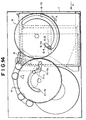
- Fig. 1A is a plan view showing the overall structure of a loading/threading mechanism of a cartridge magnetic tape apparatus
- Fig. 1B is a partial, enlarged view of Fig. 1A
- Fig. 2 is a side view of the loading/threading mechanism.
- a loading mechanism portion and a threading mechanism portion are arranged in a predetermined connecting relationship on a deck base 3.
- the loading mechanism portion is mainly located at the right side and the threading mechanism portion is mainly located at the left side.
- the loading mechanism portion functions to feed, in the direction of an arrow X, a single reel cartridge 1 inserted in the direction of the arrow X to move the single reel cartridge 1 to a predetermined position at which a magnetic tape wound in the cartridge 1 can be withdrawn and rewound, and also feed the cartridge 1 having the magnetic tape rewound therein from the above predetermined position in the direction of an arrow Y to a position at which the cartridge 1 can be discharged in the direction of the arrow Y.
- the threading mechanism portion functions to draw out the tip or leading end portion of the magnetic tape from the cartridge 1 located at the predetermined position by the loading mechanism, to guide it to a take-up reel in the magnetic tape apparatus through a predetermined route passing by a magnetic head by which recording/reproducing can be carried out on the magnetic tape, and to connect the leading end of the magnetic tape to the core portion of the machine reel.
- the threading mechanism portion also functions to pick up the tip or leading end portion of the magnetic tape from the core portion of the machine reel and move it back through the predetermined route to return it into the cartridge 1.
- Fig. 3 is a perspective view showing the cartridge 1.
- the cartridge 1 includes a casing 1-1, and a cartridge reel 1-2 which is accommodated in the casing 1-1 and around which a magnetic tape is wound.
- a door 1-3 is formed on the side end surface of the casing 1-1.
- Fig. 4 is a partial side view showing the cartridge 1 when the door 1-3 is opened
- Fig. 5 is a partial, cross-sectional view of the cartridge 1 of Fig. 4.
- the cartridge 1 is inserted into the loading mechanism portion in the direction of the arrow X shown in Figs. 3 and 4.
- the door 1-3 is biased or urged in the direction of the arrow X by biasing means or urging means such as a spring or the like (not shown), and the opening in the cartridge 1 is closed by the door 1-3 as shown in Fig. 3 before the cartridge 1 is inserted into the loading mechanism portion.
- An engaging projection 1-4 is provided on the door 1-3, and it is engaged with an engaging member in the loading mechanism portion when the cartridge 1 is loaded, whereby when the loading operation is completed, the door 1-3 is moved in the direction of the arrow Y to keep the cartridge open, as shown in Fig. 4.
- Fig. 3 only the lower surface side portion of the core portion of the cartridge reel 1-2 appears, together with a side-face gear 20.
- the side-face gear 20 of the reel engages a side-face gear 21 connected to a cartridge reel driving motor to enable a rotational drive to be provided to the cartridge reel 1-2.
- the cartridge reel 1-2 has a lock pin 1-5 projecting through the side-face gear thereof, and the lock pin 1-5 is downwardly biased until the cartridge reel 1-2 is engaged with the side-face gear 21 of a driving motor, whereby the rotation of the cartridge reel 1-2 relative to the casing 1-1 is prevented by a lock mechanism (not shown).
- the upward movement of the lock pin 1-5 through its engagement with the side-face gear 21 of the driving motor releases the lock to allow the rotation of the cartridge reel 1-2 relative to the casing 1-1.
- a leader pin 1-7 is secured to the tip of the magnetic tape 1-6 wound around the cartridge reel 1-2.
- the leader pin 1-7 is accommodated in a predetermined accommodating portion 1-8 in the casing 1-1 as shown in Figs. 4 and 5 in the condition in which the magnetic tape 1-6 is wound around the cartridge reel 1-2, whereby the leader pin 1-1 is positioned with respect to the casing 1-1.
- a loader guide plate 4 is arranged so as to be fixed in position with respect to the deck base 3, a loader drive plate 5 is arranged inside the loader guide plate 4, and a cartridge tray 2 is arranged inside the loader drive plate 5, as shown in Figs. 1 and 2.
- Fig. 6 is a front view of this embodiment, which is viewed in the cartridge insertion direction.
- Fig. 7 is a partially exploded, perspective view showing the relationships between the loader guide plate 4, the loader drive plate 5 and the cartridge tray 2.
- the cartridge 1 is inserted into the cartridge tray 2 in the direction of the arrow X.
- a pin 2-1 is arranged on one side surface of the cartridge tray 2 so as to project outwardly.
- the pin 2-1 extends so as to penetrate through the loader drive groove 5-1 and the loader guide groove 4-1.
- a roller 2-2 which is movable in and along the loader drive groove 5-1, and a roller 2-3 which is movable in and along the loader guide groove 4-1, are rotatably secured to the pin 2-1.
- These rollers 2-2 and 2-3 have flanges serving as a spacer between the side surface of the cartridge tray 2 and the side surface of the loader drive plate 5, and a spacer between the side surface of the loader drive plate 5 and the side surface of the loader guide plate 4.
- Fig. 7. the relationship between the loader guide plate 4, the loader drive plate 5 and the cartridge tray 2 is shown with respect to one side surface side. The same relationship is satisfied with respect to the other side surface side.
- Figs. 1 and 2 in addition to the pin 2-1, there is a similar pin 2-1' on the other side surface of the cartridge tray 2, which projects outwardly.
- the pin 2-1' there is a loader drive groove 5-1', as well as the loader drive groove 5-1, in the other side surface of the loader drive plate 5.
- the pin 2-1' extends so as to penetrate through the loader drive groove 5-1' and the loader guide groove 4-2, and a roller 2-2' which is movable in and along the loader drive groove 5-1', and a roller 2-3' which is movable in and along the loader guide groove 4-2, are rotatably secured to the pin 2-1' as in the case of the pin 2-1.
- a pin 5-2' on the other side surface of the loader drive plate 5 arranged to project outwardly, and a roller 5-3' which is movable in and along the loader guide groove 4-2 is rotatably secured to the pin 5-2'.
- each of the loader guide grooves 4-1, 4-2 has a horizontal portion extending in the X-direction and a vertical portion which extends substantially vertically downwardly from the end of the horizontal portion in the X-direction.
- the shapes of the loader guide grooves 4-1 and 4-2, and the positions of the pins 2-1 and 2-1', are such that the rollers 2-3, 2-3' arrive at the vertical portions of the loader guide grooves 4-1, 4-2 at the same time.
- the loader drive plate 5 and the cartridge tray 2 can be mounted on the loader guide plate 4 so as to be movable in the X and Y directions and in the direction perpendicular to the X and Y directions.
- a loader drive roller 5-4 is secured to the upper surface of the loader drive plate 5, and it extends to the upper portion of the loader guide plate 4 so as to pass through a groove 4-3 on the upper surface of the loader guide plate 4 along the X and Y directions as shown in Fig. 1.
- an engaging member 2-4 is formed on the cartridge tray 2 so as to be engageable with the engaging projection 1-4 provided to the door of the cartridge 1, and when the cartridge 1 is inserted in a predetermined position of the tray 2, the engaging projection 1-4 and the engaging member 2-4 are engaged with each other to open the cartridge door 1-3.
- An external loader drive gear 6 is disposed at the upper side of the loader guide plate 4 so as to be rotatable around the up-and-down direction relative to the deck base 3.
- the loader drive gear 6 is driven through a gear train 23 by a loader motor 22 serving as the driving means which is rotatable in either the forward or the reverse direction, as shown in Fig. 6.
- the cam groove 6-1 has a radial-direction portion 6-1a extending in the radial direction of the loader drive gear 6, and a circumferential-direction portion 6-1b which is connected to the outer end of the radial-direction portion 6-1a and extends in the circumferential direction.
- the groove width of the radial-direction portion 6-1a of the cam groove is set to be slightly larger than the outer diameter of the loader drive roller 5-4, except for the connection end portion with the circumferential-direction portion 6-1b of the cam groove.
- a spring 6-2 is secured at the X-direction side of the radial-direction portion 6-1a of the cam groove on the lower surface of the loader drive gear 6, and the spring 6-2 biases the loader drive roller 5-4 located in the radial-direction portion 6-1a in the Y direction. Accordingly, even when the loader drive gear 6 is still, the loader drive plate 5 can move slightly in the X direction against the spring 6-2 as a result of the external force while the loader drive roller 5-4 is located in the radial-direction portion 6-1a of the cam groove. That is, in Figs.
- the spring 6-2 behaves as if it forms an "X-direction movable side wall biasing in the Y direction" of the radial-direction portion 6-1a of the cam groove. In the figures, other than Figs. 1A and 1B, the spring 6-2 is omitted from the illustration.
- the cam groove 6-1 is illustrated by a solid line as if it extends so as to penetrate to the upper surface of the loader drive gear 6. However, this illustration is made for emphasis. Actually, the cam groove 6-1 is only at the lower surface side of the loader drive gear 6, as shown in Fig. 6.
- the face gear 21 and the driving motor 24 for driving the face gear 21 shown in Fig. 3 are arranged below the loader guide plate 4, the leader drive plate 5 and the cartridge tray 2, so as to be fixed in position to the deck base 3.
- a threader drive arm 7 is arranged in the threading mechanism portion so as to be rotatable around the up-and-down direction with the pin 25 at the centre of the rotation with respect to the deck base 3, as shown in Figs. 1A and 2.
- a threader drive roller 7-1 is secured on the upper surface of the threader drive arm 7 so as to be away from the pin 25 and rotatable around the up-and-down direction.
- a threading arm 8 is secured to the tip portion of the threader drive arm 7 so as to be rotatable around the up-and-down direction.
- the threader drive arm 7 and the threading arm 8 constitute the threader drive (arm) member.
- a pin 26 extending in the up-and-down direction is secured to the tip portion of the threading arm 8, and one end portion of the leader block 9 is secured to the pin 26 at a lower position than the threading arm 8.
- the pin 26 has a flange portion at its lower end, and any downward movement of the leader block 9 is prevented by the flange portion. That is, as shown in Fig. 9, the leader block 9 is provided with a through hole 9-1 which extends in the up-and-down direction and has a composite shape containing a small circle and a large circle in section.
- the pin 26 is designed so that the outer diameter of the portion thereof which penetrates through the through hole 9-1 is smaller than the diameter of the small circle, and the outer diameter of the flange portion at the lower end thereof is larger than the diameter of the large circle. Accordingly, the leader block 9 is loosely fitted to the pin 26 and held by the pin 26 so as to be rotatable around the pin 26.
- the leader block 9 has a leader pin capture groove 9-2 on the side surface of the other end portion, the leader pin capture groove 9-2 extending in the up-and-down direction and being fitted to the leader pin 1-7 affixed to the tip of the magnetic tape 1-6 to capture the leader pin 1-7.
- a downwardly projecting pin 9-3 and an upwardly projecting pin 9-4 are secured to the leader block 9.
- a threading cam 10 is arranged horizontally at a position higher than the threading arm 8.
- a threading cam groove 10-1 on the lower surface of the threading cam 10.
- a threading guide roller 27 which is secured to the upper end of the pin 26 which in turn is secured to the tip of the threading arm 8, as shown in Fig. 8.
- an external threader drive gear 11 is arranged at the upper side of the threading cam 10 so as to be rotatable around the up-and-down direction relative to the deck base 3.
- the threader drive gear 11 is engaged with the loader drive gear 6, and rotated in the reverse direction to the loader drive gear 6 when the loader drive gear rotates.
- a threader drive cam groove 11-1 is formed on the lower surface of the threader drive gear 11, and the threader drive roller 7-1 is fitted to the cam groove 11-1.
- the cam groove 11-1 has a radial-direction portion 11-1a extending in the radial direction of the threader drive gear 11 and a circumferential-direction portion 11-1b which is connected to the inner end of the radial-direction portion 11-1a and extends in the circumferential direction.
- cam groove 11-1 and the threading cam groove 10-1 are illustrated with solid lines (or illustrated with one solid line) as if they extended to the upper surface of the threader drive gear 11 and the upper surface of the threading cam 10 respectively.
- this illustration is for the purpose of emphasis, and the cam grooves 11-1 and 10-1 are actually formed only at the lower surface sides of the threader drive gear 11 and the threading cam 10 respectively, as in the case of the loader drive cam groove 6-1.
- a driving motor 30 which is fixed to the deck base 3 and a machine reel 31 which is rotationally driven around the up-and-down direction are arranged at the lower side of the threader drive arm 7 and the threading cam 10.
- Fig. 1A As shown in Fig. 1A, at the outside of the machine reel 31 in the radial direction there are plural tape guide rollers 32 and a magnetic head 34 arranged between the machine reel 31 and the threading cam groove 10-1, and located along the tape running route inside the tape running route (at the machine reel side).
- the leader block 9 is fitted to a retractor block 12.
- the retractor block 12 has a pin 12-1 extending in the up-and-down direction at the lower portion thereof, and disposed so as to be rotatable around the up-and-down direction with the pin 12-1 at the centre of the rotation with respect to the deck base 3.
- a downwardly projecting retractor pin 12-2 is formed at the lower portion of the retractor block 12 so as to be away from the rotational centre pin 12-1.
- the retractor pin 12-2 is located adjacent to the moving route of the cartridge tray 2, and it can be engaged with a retractor cam 5-5 (see Fig. 10) provided on the side surface of the loader drive plate 5 when the cartridge tray 2 is moved in the X direction.
- a linear groove 12-3 is formed on the upper surface of the retractor block 12, and the pin 9-3 of the leader block 9 is fitted to the groove 12-3 so as to be displaced from the pin 12-1.
- the leader block 9 is fitted to a horizontally-arranged guide cam 33, as shown in Fig. 10.
- the guide cam 33 is fixed to the deck base 3, and has a cam groove 33-1.
- the pin 9-4 of the leader block 9 is fitted in the cam groove 33-1.
- the cam groove 33-1 has an arcuate portion 33-1a having an arcuate shape of substantially 90 degrees and a linear portion 33-1b having a substantially linear shape which has one end connected to one end of the arcuate portion 33-1a and the other end which is opened to the outside and which extends substantially in the radial direction of the arcuate shape.
- Fig. 11 is a schematic plan view showing the machine reel 31.
- a notch 31-2 having a shape corresponding to the leader block 9 is formed in the core portion of the machine reel 31, and an upper side flange portion 31-3 of the machine reel 31 has a groove 31-4 which is connected to the notch 31-2 of the core portion at the inner periphery of the upper side flange portion 31-3 and which extends to the outer periphery. Accordingly, the leader block 9 is fitted into the notch 31-2 of the core portion of the machine reel while the leader pin 1-7 is captured in the leader pin capture groove 9-2, as shown in Fig. 11.
- Figs. 1A and 2 show the situation in which the cartridge insertion has been completed. In this situation, the cartridge 1 is allowed to be discharged (ejected) from the loading mechanism portion. The position of the cartridge tray 2 in this condition is called the "eject position".
- a lock block 36 is secured to the side surface of the cartridge tray 2 so as to be rotatable around the pin 35 extending in the up-and-down direction.
- the lock block 36 has a hook portion 36-1 formed at the tip thereof, and also a cam face portion 36-2 formed on the upper surface thereof. There is an opening 2-5, through which the hook portion 36-1 passes, in the cartridge tray 2 at the position corresponding to the hook portion 36-1 of the lock block.
- the lock block 36 is biased to the side surface of the cartridge 1 in the direction of an arrow k by biasing means (not shown).
- biasing means not shown
- a lock hole 1-9 arranged so as to be approachable at the position corresponding to the tip of the lock block 36.
- the spring 6-2 biases the loader drive roller 5-4 in the Y direction, as shown in Fig. 1B, and thus the lock block 36 is located so that the cam face portion 36-2 is fitted to a pin 37 which is fixed to the deck base 3, as shown in Fig. 12A.
- the lock block 36 is rotated in the opposite direction by a predetermined angle against the biasing force in the k direction, and the hook portion 36-1 is retracted from the opening 2-5, so that the cartridge 1 can be inserted into the cartridge tray 2 in the X direction without suffering interference by the hook portion 36-1.
- the cartridge 1 After the cartridge 1 has been inserted deeply into the cartridge tray 2, the cartridge 1 can be pushed slightly further in the X direction. This is because the loader drive roller 5-4, and thus the loader drive plate 5 can be slightly moved in the X direction against the biasing force of the spring 6-2 relative to the loader drive gear 6 at the eject position as described with reference to Figs. 1A and 1B.
- the lock block 36 Upon the movement of the cartridge 1 and the cartridge tray 2 in the X direction, the lock block 36 arrives at a position in which the fitting of the cam face portion 36-2 to the pin 37 is released. In this situation, as shown in Fig.
- the lock block 36 is rotated by the biasing force in the k direction, so that the hook portion 36-1 at the tip of the lock block 36 is passed through the opening 2-5, inserted into the lock hole 1-9 of the cartridge 1 and locked there, as shown in Fig. 12B.
- the loader drive roller 5-4 is slightly separated from the wall in the Y-direction side in the radial-direction portion 6-1A of the cam groove.
- the cartridge 1 can also subsequently be moved integrally in the X direction.
- the loading/threading operation using the driving force of the loader motor 22 can be started by detecting the insertion/lock of the cartridge 1 into/to the cartridge tray 2 at the eject position.
- the loader drive roller 5-4 is pushed in the Y direction by the fixed wall at the X-direction side of the cam groove radial-direction portion 6-1a at the connection end portion with the cam groove circumferential-direction portion 6-1b, thereby carrying-out the movement of the lock block 36 in the Y-direction from the pin 37.
- the loader drive roller 5-4 is engaged with the radial-direction portion 6-1a of the loader drive cam groove 6-1, and the threader drive roller 7-1 is engaged with the circumferential-direction portion 11-1b of the threader drive cam groove 11-1, as shown in Figs. 1A and 1B.
- the pin 2-1, 2-1' Is located at the tip in the X-direction in the slant portion of the loader drive groove 5-1, 5-1' so as to be away from the vertical portion of the loader guide groove 4-1, 4-2 at a predetermined distance in the Y direction.
- a lock mechanism for the cartridge tray 2 is set so that only when the cartridge 1 is inserted in the cartridge tray 2 in an accurate direction, is the subsequent movement of the cartridge tray 1 in the X-direction allowed.
- a lock lever 40 is secured to the cartridge tray 2 so as to be rotatable around a pin 39 extending in the up-and-down direction.
- the lock lever 40 is biased in the direction of an arrow m by appropriate means (not shown).
- An engaging portion 40-1 is formed on the lock lever 40, and it is engaged with a pin 41 which is fixed in position to the deck base 3, thereby preventing the movement of the cartridge tray 2 in the X direction.
- this situation continues until the tip of the lock lever 40 abuts against the slant side wall surface (side wall surface located obliquely to the X direction) 1-10 formed by cutting out a corner portion of the upper surface of the cartridge 1.
- the pin 41 shown in Figs. 13A and 13B is arranged at such a height that the movement of the cartridge tray 2 in the X and Y directions is not disturbed.
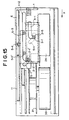
- the loader drive gear 6 is rotated in the direction of the arrow A by a predetermined angle to change the condition of the mechanism from the ejection state shown in Figs. 1A and 2 to that shown in Figs. 14 and 15.
- the cartridge 1 is moved in the X-direction, together with the cartridge tray 2 by a predetermined distance.
- the loader drive roller 5-4 is still engaged with the radial-direction portion 6-1a of the loader drive cam groove 6-1, as shown in Fig. 14, while the threader drive roller 11 is engaged with the circumferential-direction portion 11-1b of the threader drive cam groove 11-1.
- the pins 2-1, 2-1' are located at the connection position between the slant portion and the horizontal portion of the loader drive grooves 5-1, 5-1', and located at the lowest position of the vertical portion of the loader guide grooves 4-1, 4-2.
- the cartridge tray 2 as well as the cartridge 1 are moved downwardly and located at a position lower than the position corresponding to the ejection state.
- the cartridge reel in the cartridge 1 and the machine reel 31 are located at the same height.
- the downward movement of the cartridge 1 allows engagement to take place between the face gear 20 of the cartridge reel 1-2 and the face gear 21 at the driving motor side and releases the lock of the cartridge reel 1-2.
- the leader block 9 In the retracted unload position of the threading operation, the leader block 9 is kept engaged with the retractor block 12 until the mount state of the loading mechanism portion is established.
- the position of the leader block 9 in the situation in which the leader block 9 is engaged with the retractor block 12 is referred to the "unload position".
- the unload position particularly in the situation in which the leader block 9 is arranged substantially along the X-Y direction by the biasing force of the retractor spring 13, and is retracted from the cartridge movement route so that it does not obstruct the movement of the cartridge 1 as shown in Figs. 1A, 10, and 14 is referred to as the "retracted position".
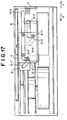
- the loader drive gear 6 is rotated in the direction of the arrow A by a predetermined angle to change the state of the mechanism from the condition shown in Figs. 14 and 15 to the condition shown in Figs. 16 and 17.
- the cartridge 1 and the cartridge tray 2 are kept in the retracted positions, however, the loader drive plate 5 is slightly advanced in the X-direction from the retracted position. That is, the pins 2-1, 2-1' are located at the Y-direction end of the horizontal portion of the loader drive grooves 5-1, 5-1'.
- the loader drive roller 5-4 is engaged with the connection portion between the radial-direction portion 6-1a and the circumferential-direction portion 6-1b of the loader drive cam groove 6-1, and the threader drive roller 11 is engaged with the circumferential-direction portion 11-1b of the threader drive cam groove 11-1.
- leader pin captured position the position of the leader block 9 corresponding to this state is referred to as the "leader pin captured position”.
- the retractor cam 5-5 (see Figs. 10, 18) fixed to the loader drive plate 5 is engaged with the retractor pin 12-2, and the retractor block 12 is rotated around the pin 12-1 in the clockwise direction of Fig. 18 by about 90 degrees against the tensile force of the spring 13, whereby the leader block 9 which is engaged with the groove 12-3 of the retractor block 12 through the pin 9-3 is rotated around the pin 26 by about 90 degrees.
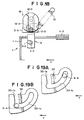
- the pin 9-4 is moved from the deepest position in the can groove arcuate portion 33-1a of the guide cam 33 shown in Fig. 19A to the connection portion between the arcuate portion 33-1A and the linear portion 33-1b of the cam groove shown in Fig. 19B.
- the rotation of the leader block 9 by substantially 90 degrees makes the tip portion of the leader block invade from the opening of the cartridge 1 into the cartridge, whereby the leader pin 1-7 located at a predetermined position in the cartridge 1 is captured by the leader pin capture groove 9-2.
- the loader drive gear 6 is rotated in the direction of the arrow A by a predetermined angle to change the state of the mechanism from the situation shown in Figs. 16 and 17 to the situation shown in Fig. 20 and then to the situation shown in Fig. 21.
- the loader drive roller 5-4 is engaged with the circumferential-direction portion 6-1b of the loader drive cam groove, and thus the X-direction positions of the loader drive plate 5, the cartridge 1 and the cartridge tray 2 are identical to those of the leader pin captured position.
- the leader block 9 is fitted to the core portion of the machine reel 31.
- the position of the leader block in the situation in which the leader block 9 is fitted to the machine reel 31 is referred to as the "load position".
- the threader drive roller 7-1 In the shift progress from the leader pin captured position to the load position, the threader drive roller 7-1 is first located in the circumferential-direction portion 11-1b of the threader drive cam groove, and thus the threader drive arm 7 and the threading arm 8 stand still (the threader drive roller 7-1 runs idle). During this idle period, the standby for the subsequent threading operation, for example, the application of the tape tension and other operations can be carried out.
- the threader drive roller 7-1 Since the threader drive roller 7-1 will soon be located in the radial-direction portion 11-1a of the threader drive cam groove, the threader drive arm 7 is rotated around the pin 25 thereby to produce horizontal tensile force to the leader block 9 through the threading arm 8 and the pin 26 secured to the tip of the threading arm 8.
- the groove 12-3 of the retractor block 12 is set to be substantially perpendicular to the X-direction as shown in Fig. 18, and the linear portion 33-1b of the cam groove 33-1 of the guide cam 33 is substantially perpendicular to the X-direction as shown in Fig. 19B. Therefore, the pin 9-3 at the lower side of the leader block 9 and the pin 9-4 at the upper side thereof can be moved in a direction substantially perpendicular to the X-direction, so as to move along the groove 12-3 and the cam groove portion 33-1.
- Fig. 20 shows the situation in which the leader block 9 is being fed at some midpoint.
- the leader block 9 invades into the notch 31-2 of the core portion of the machine reel 31 (see Fig. 11).
- the magnetic tape 1-6 thus drawn out is tensed along the tape guide roller 32 by the tensile force which is applied to the magnetic tape when the magnetic tape is drawn out of the cartridge 1, thereby allowing the magnetic head 34 to make access to the magnetic tape.
- the upper surface of the lower-end flange portion of the pin 26 is tapered, and in connection with this tapered structure, a taper surface is formed at the lower end portion of the leader block through hole 9-1. Accordingly, when the leader block is moved, the taper surface at the lower end portion of the pin through hole 9-1 and the tapered upper surface of the flange portion at the lower end of the pin 26 are engaged with each other to keep the leader block 9 at a predetermined height, whereby the tension of the magnetic tape can be well maintained.
- the rotational position of the machine reel 31 is set so that the groove 31-4 of the flange portion of the machine reel 31 and the threading cam groove 10-1 are lined up before the leader block 9 arrives at the machine reel 31.
- the setting of the rotational position may be achieved by using a combination of electrical signals obtained from photo-electric means, such as a photo-interrupter for detecting light intercepting walls which are formed along the circumferential direction on the upper or lower surface of the threader drive gear 11, so as to have a starting end and a terminating end. With this operation, the pin 26 supporting the leader block 9 can pass through the groove 31-4 of the flange portion of the machine reel 31 and advance into the notch 31-2 of the core portion.
- Figs. 22A and 22B show the variation of the relationship between the machine reel core portion 31-1 and the leader block 9 at that time. That is, before the machine reel is driven, the pin 26 is located at the rotational centre of the machine reel and brought into contact with the inner surface of the through hole 9-1 of the leader block 9, as shown in Fig. 22A. The end portion (the end portion at the leader pin capture groove side) of the leader block 9 at the opposite side to the through hole 9-1 is located so as slightly to project from the outer periphery of the reel core portion 31-1.
- the leader block 9 can be rotated integrally with the reel core by the motor 30 while the pin 26 is disposed in the through hole 9-1 having a larger inner diameter than the outer diameter of the pin 26.
- the cartridge reel and the machine reel are rotated in desired directions in a desired manner to carry out an information recording/reproducing operation on the magnetic tape 1-6 through the magnetic head 34.
- the cartridge reel 1-2 and the machine reel 31 are first set to the position as shown in Fig. 21 by the reel motors 24, 30, and then the loader motor 22 is rotated in the opposite direction to that which exists when the tape threading is carried out.
- the reel motor 24 is also rotated at a proper speed in a predetermined direction so that the proper tensile force is applied to the magnetic tape 1-6, whereby the leader block 9 is moved from the load position to the unload position (leader pin captured position), and the leader pin 1-7 arrives at the leader pin accommodation portion 1-8 of the cartridge 1.
- the loading/threading mechanism of the above-described arrangement a sequential operation of mounting the magnetic tape cartridge on to the magnetic tape apparatus, drawing the magnetic tape leading end out of the magnetic tape cartridge and connecting the magnetic tape leading end to the machine reel can be carried out by a single driving force generating source. Accordingly, the loading/threading operation can be sufficiently detected by detecting only the rotational angular position of the loader drive gear or the threader drive gear, and thus the need for a number of sensors for detecting the state of the mechanism and for controlling the apparatus can be reduced. Further, it is possible by means of this arrangement to reduce the number of driving force generating sources. Therefore, the control circuit of the apparatus can be simplified, and the apparatus can be made smaller in size and its cost reduced.
- Fig. 23 is a plan view showing another arrangement of a loading/threading mechanism of a cartridge magnetic tape apparatus.
- the elements or parts having the same functions as those described with reference to Fig. 1A to Fig. 22B are indicated by the same reference numerals.
- the loader drive cam groove and the threader drive cam groove are on the same driving gear 15.
- the threader drive cam groove has a radial-direction portion 11-1a and a circumferential-direction portion 11-1b similar to those of the first-described arrangement, however, the loader drive cam groove has a circumferential-direction portion 6-1b similar to that of the first-described arrangement and a radial/circumferential direction portion 6-1c different from that of the first-described arrangement.
- the radial/circumferential direction portion 6-1c is a non-circumferential direction groove portion having a radial direction component and a circumferential-direction component, and the inner end thereof is connected to the circumferential-direction portion 6-1b while the outer end thereof is located in the neighbourhood of the outer periphery of the driving gear 15.
- Fig. 23 there are shown the eject position of the cartridge tray and a cartridge 1' at the mount position.
- the driving gear 15 is driven by a driving motor (not shown) similar to the loader drive motor of the first-described arrangement.
- the loader drive roller 5-4 is moved in the radial/circumferential direction portion 6-1c to the circumferential direction portion 6-1b on the basis of the engagement between the loader drive roller 5-4 and the radial/circumferential direction portion 6-1c of the loader drive cam groove, and also moved in the X-direction relative to the deck base, thereby carrying out the movement of the cartridge tray from the eject position to the mount position and the subsequent movement of the leader block from the retracted position to the leader pin captured position as carried out in the first-described arrangement.
- the subsequent operation is the same as in the first-described arrangement.
- the gear is used as the driving rotator or the driving rotating member.
- a pulley, a roller or other rotator or rotating members may be used.
- the linkage between a first rotator and a second rotator may be provided by the suspension of a chain or belt around these rotators or by pressing the rotators upon each other.
Landscapes
- Replacement Of Web Rolls (AREA)
Abstract
Description
Claims (24)
- A loading/threading mechanism for a single reel cartridge magnetic tape apparatus, including a loading mechanism for moving a cartridge tray for accommodating a cartridge between an eject position in which the cartridge is rnountable/demountable into/from the cartridge tray and a mount position in which a reel of the cartridge is engaged with a cartridge reel rotating means of the magnetic tape apparatus, and a threading mechanism for moving a leader block engageable with a leader pin affixed to the tip portion of a magnetic tape accommodated in the cartridge through a predetermined route between an unload position in the neighbourhood of the cartridge tray located at the mount position and a load position in a notch of the core portion of a reel of the magnetic tape apparatus to which the leader block is fitted, wherein at the unload position, the leader block is located at a retracted position at which the leader block is retracted from the cartridge accommodated in the cartridge tray located at the mount position, and a leader pin captured position at which the leader block is engaged with the leader pin affixed to the tip portion of the magnetic tape in the cartridge accommodated in the cartridge tray located at the mount position, the loading mechanism and the threading mechanism being driven by means of a single driving force generating source.
- A loading/threading mechanism as claimed in claim 1, wherein the loading mechanism has a loader drive rotator having a loader drive cam groove, and a loader drive member which is reciprocally movable in one direction to translate the cartridge tray between the eject position and the mount position, the loader drive member having a loader drive engaging member which is engaged with the loader drive cam groove, the threading mechanism having a threader drive rotator with a threader drive cam groove and a threader drive member for driving the leader block to move between the unload position and the load position, the threader drive member having a threader drive engaging member for engaging with the threader drive cam groove, and the loader drive rotator and the threader drive rotator being connected to each other, so that a rotational driving force is transmitted therebetween, and a driving force is transmitted from the driving force generating source to one of the loader drive rotator and the threader drive rotator.
- A loading/threading mechanism as claimed in claim 1, wherein the loading mechanism has a loader drive cam groove formed in a driving rotator, and a loader drive member which is reciprocally movable in one direction to translate the cartridge tray between the eject position and the mount position, the loader drive member having a loader drive engaging member for engagement with the loader drive cam groove, the threading mechanism having a threader drive cam groove in the driving rotator and a threader drive member for driving the leader block to move between the unload position and the load position, and the threader drive member having a threader drive engaging member for engagement with the threader drive cam groove, whereby a driving force may be transmitted from the driving force generating source to the driving rotator.
- A loading/threading mechanism as claimed in either of claims 2 or claim 3, wherein the threading mechanism has a retractor for moving the loader drive member in the condition in which the cartridge tray is in the mount position, thereby shifting the leader block from the retracted position to the leader pin captured position, and the retractor having a pin which is engageable with a retractor cam secured to the loader drive member, and a groove which is engageable with a pin secured to the leader block.
- A loading/threading mechanism for a single reel cartridge magnetic tape apparatus, in which there are a loader drive cam groove and a threader drive cam groove on a rotating member, the loader drive cam groove having a first groove portion extending in the circumferential direction so as to be kept away from the rotational centre of the rotating member at a fixed distance, and a second groove portion which is linked to one end portion of the first groove portion and extends so that the distance from the rotational centre of the rotating member is varied, the loader drive cam groove being engaged with a loader drive engaging member affixed to a loader drive member, the loader drive member being engaged with a cartridge tray on which a cartridge is accommodated, whereby in the condition in which the second groove portion is engaged with the loader drive engaging member, during the rotation of the rotating member the cartridge tray is moved between an eject position at which the mount/demount of the cartridge into/from the cartridge tray are enabled and a mount position at which a reel of the cartridge is engageable with cartridge reel rotating means of the magnetic tape apparatus, the threader drive cam groove having a third groove portion extending in the circumferential direction so as to be kept away from the rotational centre of the rotating member at a fixed distance and a fourth groove portion which is linked to one end portion of the third groove portion and extends so that the distance from the rotational centre of the rotating member is varied, the threader drive cam groove being engaged with a threader drive engaging member affixed to the threader drive member, the threader drive member being connected to a leader block engageable with a leader pin affixed to the tip portion of a magnetic tape accommodated in the cartridge, whereby in the condition in which the fourth groove portion is engaged with the threader drive engaging member, during the rotation of the rotating member the leader block is moved through a predetermined route between an unload position in the neighbourhood of the cartridge tray located at the mount position and a load position in a notch of the core portion of a reel of the magnetic tape apparatus to which the leader block is fitted, the first to fourth groove portions being set so that when the loader drive engaging member is engaged with the second groove portion, the threader drive engaging member is engaged with the third groove portion, and, when the threader drive engaging member is engaged with the fourth groove portion, the loader drive engaging member is engaged with the first groove portion, and a single driving force generating source for transferring the rotational driving force to the rotating member.
- A loading/threading mechanism as claimed in claim 5, wherein the rotating member has a first rotator and a second rotator which are connected to each other so as to be rotatable in synchronism with each other, the loader drive cam groove being in the first rotator, and the threader drive cam groove being in the second rotator.
- A loading/threading mechanism as claimed in claim 6, wherein the first rotator is a loader drive gear, and the second rotator is a threader drive gear, the loader drive gear and the threader drive gear being engaged with each other.
- A loading/threading mechanism as claimed in claim 5. wherein the loader drive member moves the cartridge tray while a guide engaging member affixed to the cartridge tray is guided in engagement with a loader guide groove formed in a loader guide member.
- A loading/threading mechanism as claimed in claim 8, wherein the loader guide groove has a bend in it.
- A loading/threading mechanism as claimed in any one of claims 5 to 9, wherein the leader block is located at one of a retracted position and a leader pin captured position in the unload position, the retracted position being a position at which the leader block is retracted from the cartridge accommodated in the cartridge tray located at the mount position, and the leader pin captured position being a position at which the leader block is engaged with a leader pin affixed to the tip portion of the magnetic tape in the cartridge accommodated in the cartridge tray located at the mount position.
- A loading/threading mechanism as claimed in claim 10, including a retractor block which is rotatable to rotate the leader block located at the unload position, the retractor block being biased in one rotational direction, the loader drive member having a retractor cam which is engaged with the retractor block to rotate the retractor block in the other rotational direction, and the loader drive member being moved while the cartridge tray is located at the mount position, whereby the leader block is rotated against the biasing force to be shifted from the retracted position to the leader pin captured position.
- A loading/threading mechanism as claimed in claim 11, including a guide cam for restricting the range of the angle of rotation of the retractor block at the unload position.
- A loading/threading mechanism as claimed in claim 5, wherein the cartridge tray has an engaging member for engagement with a door of the cartridge inserted at the eject position to open the door.
- A loading/threading mechanism as claimed in claim 5, wherein the cartridge tray has a lock member which is engaged with a lock hole of the cartridge inserted to the eject position to fix the cartridge to the cartridge tray.
- A loading/threading mechanism as claimed in claim 5, including a lock mechanism for fixing the cartridge tray at the eject position, the lock mechanism abutting against the slant surface of the cartridge to release the fixing.
- A loading/threading mechanism as claimed in claim 5, wherein the leader block is rotatably held with a clearance by a support pin secured to the threader drive member, and including a threading cam groove for guiding the support pin when said leader block is moved between the unload position and the load position.
- A loading/threading mechanism for a single reel cartridge magnetic tape apparatus has a loading mechanism portion and a threading mechanism portion, in which the loading mechanism portion has a loader drive gear, a loader drive cam groove including a circumferential direction groove portion and a non-circumferential direction groove portion in the loader drive gear, the loader drive cam groove being for engagement with a loader drive engaging member affixed to a loader drive plate, the loader drive plate being engaged with a cartridge tray accommodating a cartridge, whereby in the condition in which the non-circumferential direction groove portion of the loader drive cam groove is engaged with the loader drive engaging member, during the rotation of the loader drive gear, the cartridge tray is moved between an eject position at which the mount/demount of the cartridge into/from the cartridge tray is enabled and a mount position at which a reel of the cartridge is engageable with cartridge reel rotating means of the magnetic tape apparatus, and in which the threading portion has a threader drive gear engageable with the loader drive gear, a threader drive cam groove including a circumferential direction groove portion and a non-circumferential direction groove portion in the threader drive gear, the threader drive cam groove being engaged with a threader drive engaging member which is affixed to a threader drive arm member rotatable around the rotating centre parallel to the rotational centre of the threader drive gear so as to be eccentric to the rotating centre, the threader drive arm member being connected to a leader block engageable with a leader pin affixed to the tip portion of a magnetic tape accommodated in the cartridge, whereby in the condition in which the non-circumferential direction groove portion of the threader drive cam groove is engaged with the threader drive engaging member, during the rotation of the threader drive gear, the leader block is moved through a predetermined route between an unload position in the neighbourhood of the cartridge tray located at the mount position and a load position in a notch of the core portion of a reel of the magnetic tape apparatus to which the leader block is fitted, the loader drive gear and the threader drive gear being engaged with each other, so that, when the loader drive engaging member is engaged with the non-circumferential direction groove portion of the loader drive cam groove, the threader drive engaging member is engage with the circumferential direction groove portion of the threader drive cam groove, arid when the threader drive engaging member is engaged with the non-circumferential direction groove portion of the threader drive cam groove, the loader drive engaging member is engaged with the circumferential direction groove portion of the loader drive cam groove, and a driving motor for driving the rotation of the loader drive gear or the threader drive gear.
- A loading/threading mechanism for a single reel cartridge magnetic tape apparatus, including a driving rotator, a loader drive cam groove including a first circumferential direction groove portion and a first non-circumferential direction groove portion and a threader drive cam groove inlcuding a second circumferential direction groove portion and a second non-circumferential direction groove portion in the driving rotator. the loader drive cam groove is engaged with a loader drive engaging member affixed to a loader drive plate, the loader drive plate being engaged with a cartridge tray for accommodating a cartridge, whereby in the condition in which the first non-circumferential direction groove portion of the loader drive cam groove is engaged with the loader drive engaging member, during the rotation of the rotator, the cartridge tray is moved between an eject position at which the mount/demount of the cartridge into/from the cartridge tray is enabled and a mount position at which a reel of the cartridge is engageable with cartridge reel rotating means of the magnetic tape apparatus, the threader drive cam groove being engaged with a threader drive engaging member which is affixed to a threader drive arm member rotatable around the rotating centre parallel to the rotational centre of the rotator so as to be eccentric to the rotating centre, the threader drive arm being connected to a leader block engageable with a leader pin affixed to the tip portion of a magnetic tape accommodated in the cartridge, whereby in the condition in which the second non-circumferential direction groove portion of the threader drive cam groove is engaged with the threader drive engaging member, during the rotation of the rotator, the leader block is moved through a predetermined route between an unload position in the neighbourhood of the cartridge tray located at the mount position and a load position in a notch of the core portion of a reel of the magnetic tape apparatus to which the leader block is fitted, and the loader drive cam groove and the threader drive cam groove having such a phase that, when the loader drive engaging member is engaged with the first non-circumferential direction groove portion of the loader drive cam groove, the threader drive engaging member is engaged with the second circumferential direction groove portion of the threader drive cam groove, and when the threader drive engaging member is engaged with the second non-circumferential direction groove portion of the threader drive cam groove, the loader drive engaging member is engaged with the first circumferential direction groove portion of the loader drive cam groove.
- A loading/threading mechanism as claimed in either claim 17 or claim 18, including a retractor block engageable with the leader block located at the unload position, wherein the retractor block is rotatable between a first attitude and a second attitude and biased so as to assume the first attitude as a result of the biasing means, and the retractor block being engaged with the leader block so that when in the first attitude the leader block is retracted from the cartridge accommodated in the cartridge tray located at the mount position, while in the second attitude the leader block is advanced to the cartridge accommodated in the cartridge tray located at the mount position, the retractor block being set to the second attitude against the biasing force of the biasing means when a retractor cam affixed to the loader drive plate abuts against the retractor block.
- A loading/threading mechanism as claimed in claim 19, wherein the biasing means is a spring.
- A loading/threading mechanism as claimed in claim 19, wherein the leader block is rotatably secured to the threader drive arm member and has an engaging projection which is engageable with the retractor block, and the retractor block has an engaging groove which is engageable with the engaging projection.
- A loading/threading mechanism as claimed in either claim 17 or claim 18, wherein a leader pin capture groove engageable with the leader pin is formed in the leader block.
- A loading/threading mechanism as claimed in either claim 17 or claim 18, including a threading guide groove for setting the predetermined route of the movement of the leader block, and said threader drive arm member has a threading guide engaging member which is engageable with the threading guide groove.
- A loading/threading mechanism as claimed in either claim 17 or claim 18, wherein the threader drive arm member has a first arm portion which is rotatable around the rotating centre and has the threader drive engaging member, and a second arm portion which is rotatably connected to the first arm portion and connected to the leader block.
Applications Claiming Priority (2)
| Application Number | Priority Date | Filing Date | Title |
|---|---|---|---|
| JP13702899A JP3390361B2 (en) | 1999-05-18 | 1999-05-18 | Loading / threading mechanism of cartridge magnetic tape unit |
| JP13702899 | 1999-05-18 |
Publications (3)
| Publication Number | Publication Date |
|---|---|
| EP1054396A2 true EP1054396A2 (en) | 2000-11-22 |
| EP1054396A3 EP1054396A3 (en) | 2000-12-06 |
| EP1054396B1 EP1054396B1 (en) | 2007-06-13 |
Family
ID=15189167
Family Applications (1)
| Application Number | Title | Priority Date | Filing Date |
|---|---|---|---|
| EP00304193A Expired - Lifetime EP1054396B1 (en) | 1999-05-18 | 2000-05-18 | Tape apparatus mechanism |
Country Status (3)
| Country | Link |
|---|---|
| US (1) | US6437938B1 (en) |
| EP (1) | EP1054396B1 (en) |
| JP (1) | JP3390361B2 (en) |
Cited By (6)
| Publication number | Priority date | Publication date | Assignee | Title |
|---|---|---|---|---|
| EP1098307A3 (en) * | 1999-11-05 | 2001-07-18 | Nec Corporation | Threading mechanism for magnetic recording/reproducing apparatus |
| EP1453046A2 (en) | 2003-02-27 | 2004-09-01 | Tandberg Data ASA | System for extracting magnetic recording tape from a tape cartridge for engagement with a take-up reel |
| EP1313102A3 (en) * | 2001-10-19 | 2006-05-24 | NEC Corporation | Tape cartridge with tape having a leader pin |
| EP1271503A3 (en) * | 2001-06-29 | 2006-06-07 | NEC Corporation | Cartridge engaging mechanism |
| EP1517319A3 (en) * | 2003-09-04 | 2008-07-02 | Quantum Corporation | Tape cartridge soft load mechanism |
| US7540442B2 (en) | 2004-06-17 | 2009-06-02 | Nec Corporation | Apparatus for threading a tape from a cartridge |
Families Citing this family (23)
| Publication number | Priority date | Publication date | Assignee | Title |
|---|---|---|---|---|
| US6626387B1 (en) * | 2000-07-25 | 2003-09-30 | Seagate Removable Storage Solutions Llc | Rolling element for guiding a hub filler in a tape drive |
| US6865047B2 (en) * | 2000-11-02 | 2005-03-08 | Sony Corporation | Single reel tape cartridge and recording and reproducing device using the tape cartridge |
| JP4146624B2 (en) * | 2001-05-28 | 2008-09-10 | 富士フイルム株式会社 | Leader pin attachment / detachment measuring device for magnetic tape cartridge |
| JP3718154B2 (en) | 2001-10-15 | 2005-11-16 | 富士写真フイルム株式会社 | Recording tape cartridge |
| JP4009081B2 (en) | 2001-10-15 | 2007-11-14 | 富士フイルム株式会社 | Recording tape cartridge |
| JP3710405B2 (en) | 2001-10-15 | 2005-10-26 | 富士写真フイルム株式会社 | Recording tape cartridge |
| JP3607659B2 (en) * | 2001-10-18 | 2005-01-05 | Necパーソナルプロダクツ株式会社 | Magnetic tape drive device |
| JP3710412B2 (en) | 2001-11-20 | 2005-10-26 | 富士写真フイルム株式会社 | Recording tape cartridge |
| JP3710414B2 (en) | 2001-11-20 | 2005-10-26 | 富士写真フイルム株式会社 | Recording tape cartridge |
| US6854678B2 (en) | 2001-11-20 | 2005-02-15 | Fuji Photo Film Co., Ltd. | Recording tape cartridge and drive device |
| JP3710411B2 (en) | 2001-11-20 | 2005-10-26 | 富士写真フイルム株式会社 | Recording tape cartridge |
| JP3710413B2 (en) | 2001-11-20 | 2005-10-26 | 富士写真フイルム株式会社 | Recording tape cartridge |
| JP3577031B2 (en) | 2001-12-03 | 2004-10-13 | Necパーソナルプロダクツ株式会社 | Cartridge lock mechanism for magnetic tape unit |
| JP4000279B2 (en) | 2002-05-29 | 2007-10-31 | 富士フイルム株式会社 | Recording tape cartridge |
| US6889927B2 (en) * | 2002-07-03 | 2005-05-10 | Segway Systems, Llc | Tape threading apparatus having take-up hub with gap filling block for data storage systems and method therefor |
| JP2004046923A (en) * | 2002-07-09 | 2004-02-12 | Fuji Photo Film Co Ltd | Recording tape cartridge |
| TW560680U (en) * | 2002-11-18 | 2003-11-01 | Benq Corp | Disk drive with eject function |
| JP3826880B2 (en) | 2002-11-21 | 2006-09-27 | 日本電気株式会社 | Threading mechanism in magnetic recording / reproducing apparatus |
| US7224549B1 (en) | 2004-05-17 | 2007-05-29 | Storage Technology Corporation | Apparatus for positioning a data storage device |
| JP4191093B2 (en) * | 2004-06-08 | 2008-12-03 | Necパーソナルプロダクツ株式会社 | Cartridge tray provided in the cartridge drive device |
| JP4593355B2 (en) * | 2005-05-12 | 2010-12-08 | Necパーソナルプロダクツ株式会社 | Magnetic tape unit |
| JP4887236B2 (en) * | 2007-08-08 | 2012-02-29 | 日立マクセル株式会社 | Magnetic tape reel, tape cartridge using the same, recording / reproducing apparatus for recording / reproducing information on the tape cartridge, information recording / reproducing method thereof, and positioning mechanism |
| JP2010238349A (en) * | 2009-03-12 | 2010-10-21 | Nec Personal Products Co Ltd | Magnetic head cleaning mechanism and magnetic tape device |
Family Cites Families (16)
| Publication number | Priority date | Publication date | Assignee | Title |
|---|---|---|---|---|
| US4608614A (en) * | 1983-06-24 | 1986-08-26 | International Business Machines Corp. | Apparatus for threading magnetic tape in a magnetic tape transport |
| US4991037A (en) | 1986-03-26 | 1991-02-05 | Copal Co., Ltd. | Apparatus for manipulating a magnetic tape cartridge and the magnetic tape contained therewithin |
| JPS63108551A (en) | 1986-10-27 | 1988-05-13 | Nakamichi Corp | Leader block pulling-out device |
| JPS63193234U (en) | 1987-05-27 | 1988-12-13 | ||
| JPH01192049A (en) | 1988-01-27 | 1989-08-02 | Nakamichi Corp | Magnetic recording and reproducing device |
| JPH01192050A (en) * | 1988-01-27 | 1989-08-02 | Nakamichi Corp | Magnetic recording and reproducing device |
| JPH0268344U (en) | 1988-11-10 | 1990-05-23 | ||
| JP2640692B2 (en) * | 1990-07-18 | 1997-08-13 | 富士通株式会社 | Tape threading mechanism of magnetic tape device and method of controlling tape threading mechanism |
| US5243477A (en) * | 1991-12-17 | 1993-09-07 | Datatape Incorporated | Apparatus for threading magnetic tape from a single reel cartridge in a rotary head tape transport |
| JP2930506B2 (en) * | 1993-09-10 | 1999-08-03 | 富士通株式会社 | Magnetic tape unit |
| JPH0817111A (en) | 1994-06-30 | 1996-01-19 | Hitachi Ltd | Magnetic recording / reproducing device |
| JP2853617B2 (en) | 1995-10-27 | 1999-02-03 | 日本電気株式会社 | Cartridge magnetic tape unit |
| US6034839A (en) * | 1997-11-07 | 2000-03-07 | Seagate Technology, Inc. | Mechanism and method for loading a tape from a cartridge to a take-up reel |
| CN1169137C (en) | 1998-11-12 | 2004-09-29 | 皇家菲利浦电子有限公司 | Recording and/or reproducing device with drive means for actuating a cassette holder device and a holding means of a tape pull-out element |
| EP1055235A2 (en) | 1998-11-12 | 2000-11-29 | Jabil Circuit Cayman L.P. | Recording and/or reproducing device having compact drive means for driving the actuating means of a cassette holder means |
| CN1134776C (en) | 1998-11-12 | 2004-01-14 | 皇家菲利浦电子有限公司 | Storage device, storage container and storage system |
-
1999
- 1999-05-18 JP JP13702899A patent/JP3390361B2/en not_active Expired - Fee Related
-
2000
- 2000-05-17 US US09/572,289 patent/US6437938B1/en not_active Expired - Lifetime
- 2000-05-18 EP EP00304193A patent/EP1054396B1/en not_active Expired - Lifetime
Cited By (9)
| Publication number | Priority date | Publication date | Assignee | Title |
|---|---|---|---|---|
| EP1098307A3 (en) * | 1999-11-05 | 2001-07-18 | Nec Corporation | Threading mechanism for magnetic recording/reproducing apparatus |
| US6471150B1 (en) | 1999-11-05 | 2002-10-29 | Nec Corporation | Threading mechanism for magnetic recording/reproducing apparatus |
| EP1271503A3 (en) * | 2001-06-29 | 2006-06-07 | NEC Corporation | Cartridge engaging mechanism |
| EP1313102A3 (en) * | 2001-10-19 | 2006-05-24 | NEC Corporation | Tape cartridge with tape having a leader pin |
| EP1453046A2 (en) | 2003-02-27 | 2004-09-01 | Tandberg Data ASA | System for extracting magnetic recording tape from a tape cartridge for engagement with a take-up reel |
| EP1453046A3 (en) * | 2003-02-27 | 2007-05-02 | Tandberg Data ASA | System for extracting magnetic recording tape from a tape cartridge for engagement with a take-up reel |
| EP1517319A3 (en) * | 2003-09-04 | 2008-07-02 | Quantum Corporation | Tape cartridge soft load mechanism |
| US7424983B2 (en) | 2003-09-04 | 2008-09-16 | Quantum Corporation | Tape cartridge soft load system |
| US7540442B2 (en) | 2004-06-17 | 2009-06-02 | Nec Corporation | Apparatus for threading a tape from a cartridge |
Also Published As
| Publication number | Publication date |
|---|---|
| JP3390361B2 (en) | 2003-03-24 |
| EP1054396B1 (en) | 2007-06-13 |
| EP1054396A3 (en) | 2000-12-06 |
| US6437938B1 (en) | 2002-08-20 |
| JP2000331403A (en) | 2000-11-30 |
Similar Documents
| Publication | Publication Date | Title |
|---|---|---|
| EP1054396B1 (en) | Tape apparatus mechanism | |
| KR940001247B1 (en) | Cassette loading divice for vcr | |
| JPH11110860A (en) | Tray loading mechanism of recording / reproducing device | |
| US6320722B1 (en) | Cartridge mis-insertion preventing mechanism | |
| JPH11120657A (en) | Disc loading mechanism | |
| KR100814972B1 (en) | Tape drive unit and tape ejector unit and tape cartridge | |
| US6762903B2 (en) | Tape drive | |
| US5724207A (en) | Cassette holder for individually holding different size cassettes | |
| JPH0619886B2 (en) | Magnetic recording / reproducing device | |
| CN1029436C (en) | Cassette loading facility | |
| US6710971B2 (en) | Interpose lever which can be reduced in number of components and assembling steps and tape drive using the same | |
| JP2003022595A (en) | Cassette holder device | |
| US4807216A (en) | Recording disc playback apparatus | |
| JP3541543B2 (en) | Recording / playback device | |
| JP4114356B2 (en) | Cassette holder device | |
| US20030001039A1 (en) | Cartridge engaging mechanism | |
| JP3118399B2 (en) | Cassette mounting device | |
| JPS63214956A (en) | Lock releasing mechanism for cassette attaching detaching device | |
| JP3127637B2 (en) | Recording and playback device | |
| US20050235305A1 (en) | Disk apparatus | |
| JP3354381B2 (en) | Disk changer device | |
| JPS61137260A (en) | Recording and reproducing device | |
| US20050235297A1 (en) | Disk apparatus | |
| JPH11110861A (en) | Tray loading mechanism of recording / reproducing device | |
| JP2001014760A (en) | Cassette loading device |
Legal Events
| Date | Code | Title | Description |
|---|---|---|---|
| PUAI | Public reference made under article 153(3) epc to a published international application that has entered the european phase |
Free format text: ORIGINAL CODE: 0009012 |
|
| PUAL | Search report despatched |
Free format text: ORIGINAL CODE: 0009013 |
|
| AK | Designated contracting states |
Kind code of ref document: A2 Designated state(s): FR GB |
|
| AX | Request for extension of the european patent |
Free format text: AL;LT;LV;MK;RO;SI |
|
| AK | Designated contracting states |
Kind code of ref document: A3 Designated state(s): AT BE CH CY DE DK ES FI FR GB GR IE IT LI LU MC NL PT SE |
|
| AX | Request for extension of the european patent |
Free format text: AL;LT;LV;MK;RO;SI |
|
| 17P | Request for examination filed |
Effective date: 20001122 |
|
| AKX | Designation fees paid |
Free format text: FR GB |
|
| REG | Reference to a national code |
Ref country code: DE Ref legal event code: 8566 |
|
| GRAP | Despatch of communication of intention to grant a patent |
Free format text: ORIGINAL CODE: EPIDOSNIGR1 |
|
| GRAS | Grant fee paid |
Free format text: ORIGINAL CODE: EPIDOSNIGR3 |
|
| GRAA | (expected) grant |
Free format text: ORIGINAL CODE: 0009210 |
|
| AK | Designated contracting states |
Kind code of ref document: B1 Designated state(s): FR GB |
|
| REG | Reference to a national code |
Ref country code: GB Ref legal event code: FG4D |
|
| ET | Fr: translation filed | ||
| PLBE | No opposition filed within time limit |
Free format text: ORIGINAL CODE: 0009261 |
|
| STAA | Information on the status of an ep patent application or granted ep patent |
Free format text: STATUS: NO OPPOSITION FILED WITHIN TIME LIMIT |
|
| 26N | No opposition filed |
Effective date: 20080314 |
|
| REG | Reference to a national code |
Ref country code: GB Ref legal event code: 732E Free format text: REGISTERED BETWEEN 20150212 AND 20150219 |
|
| REG | Reference to a national code |
Ref country code: FR Ref legal event code: TP Owner name: NEC PLATFORMS, LTD., JP Effective date: 20150217 |
|
| REG | Reference to a national code |
Ref country code: FR Ref legal event code: PLFP Year of fee payment: 17 |
|
| PGFP | Annual fee paid to national office [announced via postgrant information from national office to epo] |
Ref country code: GB Payment date: 20160518 Year of fee payment: 17 |
|
| PGFP | Annual fee paid to national office [announced via postgrant information from national office to epo] |
Ref country code: FR Payment date: 20160412 Year of fee payment: 17 |
|
| GBPC | Gb: european patent ceased through non-payment of renewal fee |
Effective date: 20170518 |
|
| REG | Reference to a national code |
Ref country code: FR Ref legal event code: ST Effective date: 20180131 |
|
| PG25 | Lapsed in a contracting state [announced via postgrant information from national office to epo] |
Ref country code: GB Free format text: LAPSE BECAUSE OF NON-PAYMENT OF DUE FEES Effective date: 20170518 |
|
| PG25 | Lapsed in a contracting state [announced via postgrant information from national office to epo] |
Ref country code: FR Free format text: LAPSE BECAUSE OF NON-PAYMENT OF DUE FEES Effective date: 20170531 |