EP1054380A1 - Color display device and color display method - Google Patents
Color display device and color display method Download PDFInfo
- Publication number
- EP1054380A1 EP1054380A1 EP99973154A EP99973154A EP1054380A1 EP 1054380 A1 EP1054380 A1 EP 1054380A1 EP 99973154 A EP99973154 A EP 99973154A EP 99973154 A EP99973154 A EP 99973154A EP 1054380 A1 EP1054380 A1 EP 1054380A1
- Authority
- EP
- European Patent Office
- Prior art keywords
- color
- light
- image
- display device
- color display
- Prior art date
- Legal status (The legal status is an assumption and is not a legal conclusion. Google has not performed a legal analysis and makes no representation as to the accuracy of the status listed.)
- Ceased
Links
Images


Classifications
-
- G—PHYSICS
- G09—EDUCATION; CRYPTOGRAPHY; DISPLAY; ADVERTISING; SEALS
- G09G—ARRANGEMENTS OR CIRCUITS FOR CONTROL OF INDICATING DEVICES USING STATIC MEANS TO PRESENT VARIABLE INFORMATION
- G09G3/00—Control arrangements or circuits, of interest only in connection with visual indicators other than cathode-ray tubes
- G09G3/20—Control arrangements or circuits, of interest only in connection with visual indicators other than cathode-ray tubes for presentation of an assembly of a number of characters, e.g. a page, by composing the assembly by combination of individual elements arranged in a matrix no fixed position being assigned to or needed to be assigned to the individual characters or partial characters
- G09G3/2003—Display of colours
-
- G—PHYSICS
- G09—EDUCATION; CRYPTOGRAPHY; DISPLAY; ADVERTISING; SEALS
- G09G—ARRANGEMENTS OR CIRCUITS FOR CONTROL OF INDICATING DEVICES USING STATIC MEANS TO PRESENT VARIABLE INFORMATION
- G09G3/00—Control arrangements or circuits, of interest only in connection with visual indicators other than cathode-ray tubes
- G09G3/20—Control arrangements or circuits, of interest only in connection with visual indicators other than cathode-ray tubes for presentation of an assembly of a number of characters, e.g. a page, by composing the assembly by combination of individual elements arranged in a matrix no fixed position being assigned to or needed to be assigned to the individual characters or partial characters
- G09G3/34—Control arrangements or circuits, of interest only in connection with visual indicators other than cathode-ray tubes for presentation of an assembly of a number of characters, e.g. a page, by composing the assembly by combination of individual elements arranged in a matrix no fixed position being assigned to or needed to be assigned to the individual characters or partial characters by control of light from an independent source
- G09G3/3406—Control of illumination source
- G09G3/3413—Details of control of colour illumination sources
-
- G—PHYSICS
- G09—EDUCATION; CRYPTOGRAPHY; DISPLAY; ADVERTISING; SEALS
- G09G—ARRANGEMENTS OR CIRCUITS FOR CONTROL OF INDICATING DEVICES USING STATIC MEANS TO PRESENT VARIABLE INFORMATION
- G09G2310/00—Command of the display device
- G09G2310/02—Addressing, scanning or driving the display screen or processing steps related thereto
- G09G2310/0235—Field-sequential colour display
-
- G—PHYSICS
- G09—EDUCATION; CRYPTOGRAPHY; DISPLAY; ADVERTISING; SEALS
- G09G—ARRANGEMENTS OR CIRCUITS FOR CONTROL OF INDICATING DEVICES USING STATIC MEANS TO PRESENT VARIABLE INFORMATION
- G09G2320/00—Control of display operating conditions
- G09G2320/02—Improving the quality of display appearance
- G09G2320/0242—Compensation of deficiencies in the appearance of colours
-
- G—PHYSICS
- G09—EDUCATION; CRYPTOGRAPHY; DISPLAY; ADVERTISING; SEALS
- G09G—ARRANGEMENTS OR CIRCUITS FOR CONTROL OF INDICATING DEVICES USING STATIC MEANS TO PRESENT VARIABLE INFORMATION
- G09G2320/00—Control of display operating conditions
- G09G2320/02—Improving the quality of display appearance
- G09G2320/0261—Improving the quality of display appearance in the context of movement of objects on the screen or movement of the observer relative to the screen
-
- G—PHYSICS
- G09—EDUCATION; CRYPTOGRAPHY; DISPLAY; ADVERTISING; SEALS
- G09G—ARRANGEMENTS OR CIRCUITS FOR CONTROL OF INDICATING DEVICES USING STATIC MEANS TO PRESENT VARIABLE INFORMATION
- G09G2360/00—Aspects of the architecture of display systems
- G09G2360/18—Use of a frame buffer in a display terminal, inclusive of the display panel
-
- G—PHYSICS
- G09—EDUCATION; CRYPTOGRAPHY; DISPLAY; ADVERTISING; SEALS
- G09G—ARRANGEMENTS OR CIRCUITS FOR CONTROL OF INDICATING DEVICES USING STATIC MEANS TO PRESENT VARIABLE INFORMATION
- G09G3/00—Control arrangements or circuits, of interest only in connection with visual indicators other than cathode-ray tubes
- G09G3/20—Control arrangements or circuits, of interest only in connection with visual indicators other than cathode-ray tubes for presentation of an assembly of a number of characters, e.g. a page, by composing the assembly by combination of individual elements arranged in a matrix no fixed position being assigned to or needed to be assigned to the individual characters or partial characters
- G09G3/34—Control arrangements or circuits, of interest only in connection with visual indicators other than cathode-ray tubes for presentation of an assembly of a number of characters, e.g. a page, by composing the assembly by combination of individual elements arranged in a matrix no fixed position being assigned to or needed to be assigned to the individual characters or partial characters by control of light from an independent source
- G09G3/3433—Control arrangements or circuits, of interest only in connection with visual indicators other than cathode-ray tubes for presentation of an assembly of a number of characters, e.g. a page, by composing the assembly by combination of individual elements arranged in a matrix no fixed position being assigned to or needed to be assigned to the individual characters or partial characters by control of light from an independent source using light modulating elements actuated by an electric field and being other than liquid crystal devices and electrochromic devices
- G09G3/346—Control arrangements or circuits, of interest only in connection with visual indicators other than cathode-ray tubes for presentation of an assembly of a number of characters, e.g. a page, by composing the assembly by combination of individual elements arranged in a matrix no fixed position being assigned to or needed to be assigned to the individual characters or partial characters by control of light from an independent source using light modulating elements actuated by an electric field and being other than liquid crystal devices and electrochromic devices based on modulation of the reflection angle, e.g. micromirrors
-
- G—PHYSICS
- G09—EDUCATION; CRYPTOGRAPHY; DISPLAY; ADVERTISING; SEALS
- G09G—ARRANGEMENTS OR CIRCUITS FOR CONTROL OF INDICATING DEVICES USING STATIC MEANS TO PRESENT VARIABLE INFORMATION
- G09G3/00—Control arrangements or circuits, of interest only in connection with visual indicators other than cathode-ray tubes
- G09G3/20—Control arrangements or circuits, of interest only in connection with visual indicators other than cathode-ray tubes for presentation of an assembly of a number of characters, e.g. a page, by composing the assembly by combination of individual elements arranged in a matrix no fixed position being assigned to or needed to be assigned to the individual characters or partial characters
- G09G3/34—Control arrangements or circuits, of interest only in connection with visual indicators other than cathode-ray tubes for presentation of an assembly of a number of characters, e.g. a page, by composing the assembly by combination of individual elements arranged in a matrix no fixed position being assigned to or needed to be assigned to the individual characters or partial characters by control of light from an independent source
- G09G3/36—Control arrangements or circuits, of interest only in connection with visual indicators other than cathode-ray tubes for presentation of an assembly of a number of characters, e.g. a page, by composing the assembly by combination of individual elements arranged in a matrix no fixed position being assigned to or needed to be assigned to the individual characters or partial characters by control of light from an independent source using liquid crystals
- G09G3/3611—Control of matrices with row and column drivers
Definitions
- the present invention relates to a color display device for and a color display method of implementing a color image generation as being time-division driven.
- a DMD projector which displays a color image by irradiating colored lights of R (Red), G (Green), and B (Blue) that are generated by being passed through a color filter disk which rotates a light from a white color light source onto an array of a digital micro-mirror device arrays (DMD: e.g., a device developed by Texas Instruments Incorporated) in a time sequence and by projecting the colored lights modulated/reflected with this DMD array onto a screen.
- DMD digital micro-mirror device arrays
- the color light source for generating the colored lights of R, G, B is arranged behind the liquid crystal panel that implements a black and white display.
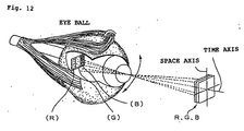
- the color band of the colored lights of R (Red), G (Green), B (Blue) are formed physically on a retina (or retinas) by an eye movement occurring voluntarily or involuntarily, and caused thereby is a phenomena (hereinafter, it is referred to as a color breakup) in which a color separation is perceived psychologically.
- Fig. 12 shows a mechanism with which the color band of RGB colored lights are formed physically on the retina by the eye movement which occurs voluntarily or involuntarily, at a time when seeing the RGB original image that is created by driving three colored lights in a time sequence (hereinafter, it is referred to as a color sequence).
- a color sequence a time sequence
- a R image, a G image, and a B image are generated without any phase displacement spatially.
- a human being recognizes the respective color images of these RGB as the color images that are equivalent to the original images by additive mixing of color stimuli time-integrally with a visual center of higher order.
- human beings experiences a line of sight shift and blink unconsciously or consciously.
- the respective images of RGB that are generated time-integrally by the color sequence driving are influenced spatially with the eye movements, and the color band of RGB is formed physically on the retina as shown in Fig. 12. This is perceived as color breakup within the visual center of higher order.
- a vertical axis represents time and a horizontal axis represents space.
- the figure shows the three-frame images, in the color image with the color sequence driving, it is a system which color-composes the R image, the G image, the B image that are generated on the retina with a time-difference determined uniquely by the frame frequency within the visual center of higher order.
- the R image, the G image, the B image for example, AR image, AG image, AB image
- the R image, the G image, the B image for example, AR image, AG image, AB image
- the time-difference that is determined uniquely by the frame frequency
- a time-difference in which the R image, the G image, the B image (for example, AR image, AG' image, AB' image) that form one frame are determined uniquely by the frame frequency, and a spatial position displacement that is determined uniquely by the eye movement rate are generated on the retina simultaneously.
- This phenomena occurs only when the eye movement is generated, and it does not occur at a time when the eyeball is in a stationary state or is in a relative stationary state (for example, in a state as following a movement of a fly). Further, this is such that a generation situation differs depending on the direction of the eye movement (for example, the AR image, AG' image, AB' image that are the first frame on the right side of Fig. 13, and the CR image, CG' image, CB' image that are the third frame thereof are such that their generation directions thereof are reversed).
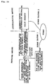
- Fig. 14 is an illustrative drawing showing a color image generation model according to a combination of the color sequence driving system as such and a visual system.
- the color image generation according to the color sequence driving system it is required to develop a color display device by considering the eye movement of the human factor 1 and the psychological color breakup perception of the human factor 2.
- the projection type display device upon considering these human factors, it will be an object to control a generation of the color breakup that is perceived as being caused by an action and the like performed by a presenter who performs a presentation such as when standing in front of a screen.
- Such color breakup is configured as to be not perceived by physically narrowing the width of the color band by contracting the time difference of the three colored lights by increasing the frame frequency to be about 2000 Hz - 3000 Hz, but for the frame frequency of about 120 Hz in the present situation, the image generation drive and the color generation drive with the higher frame frequency such as 2000 Hz - 3000 Hz are difficult in practice.
- the present invention is made in light of the above-mentioned problems, and an object of the present invention is to provide a color display device of a time-division driving system and a color display method thereof, in which there occurs no perception of a color breakup being caused by an action performed by a presenter, as well as perception of a color breakup being caused by an eye movement.
- the color display device of the present invention comprises a colored light generation unit for repetitively generating a plurality of colored lights in a time sequence with a predetermined frequency and an image generation unit for processing the plurality of colored lights, so as to generate an image corresponding to each of the plurality of colored lights generated in a time sequence, wherein the predetermined frequency is 180 Hz, thereby the above-mentioned object can be achieved.
- the predetermined frequency is 250 Hz.
- the predetermined frequency is 300 Hz.
- the colored light generation unit comprises a light source, and a color filter for generating the plurality of colored lights from light coming from the light source.
- the colored light generation unit comprises a plurality of light sources for emitting colored lights different from each other, wherein the plurality of light sources turn on in a time sequence.
- the image generation unit is a reflective type electro-optic device, according to any of the color display devices in claims 1 - 5.
- the electro-optic device is a liquid crystal device.
- the electro-optic device is a digital micro-mirror device.
- the image generation unit comprises a transmission-type electro-optic device.
- the color display device further comprises a lens for projecting the image.
- a color display method of the present invention comprises a colored light generation step for repetitively generating a plurality of colored lights in a time sequence with a predetermined frequency and an image generation step for processing the plurality of colored lights, so as to generate an image corresponding to each of the plurality of colored lights generated in a time sequence, wherein said predetermined frequency is 180 Hz, thereby the above-mentioned object can be achieved.
- the predetermined frequency is 250 Hz.
- the predetermined frequency is 300 Hz.
- a repetition frequency range of the colored lights in which a color identification in a visual system is lowered for example, enables control or prevention of color breakup that is caused by an action of a presenter who performs a presentation such as when standing in front of a screen or an object in front of the screen. Further, it also enables prevention of color breakup that is caused by an eye movement of an observer. In addition, it enables driving with a repetition frequency in a practical range without drastically increasing the repetition frequency of the colored light generation of the color display device of the time-division driving system.
- a person who watches a displayed image on a screen no longer has a sense of an incongruous image, and it has an advantage of enhancing a quality of an observed image while reducing a sense of fatigue accompanied by the image observation.
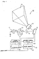
- Fig. 1 shows a first embodiment of a color display device and a driving method of the color display device according to the present invention.
- the color display device 10 of the present embodiment is a color display device that comprises a light source 11 for emitting a white light including the respective spectra of a red colored light, a blue colored light and a green colored light, a rotary color filter 12 being disposed in front of this light source 11 and having areas of color elements for red, blue and green, a condenser lens 13 being disposed in front of the rotary color filter 12, an electro-optic device 14 for generating a color image corresponding to a color of a colored light incident through the condenser lens 13, and a projection lens 15 for performing a projection upon receiving a light that is reflected/modulated in the electro-optic device 14, and an image is displayed as an image generation colored light being projected from the projection lens 15 onto a screen 16.
- the light source 11 there is provided a reflector 11a for reflecting a light from the light source as shown.
- An observer who watches an image projected onto the screen might watch the projected image by being situated in front of the screen 16 if the color display device is a front projection type, or by being situated at the rear of the screen 16 if the color display device is a rear projection type.
- a presenter human being
- One of the advantages of the present invention is to solve a perception problem of a conventional color breakup and a detailed configuration for this will be described below.
- various kinds of modulators having a high-speed response such as a ferroelectric liquid crystal panel, an antiferroelectric liquid crystal panel, a liquid crystal panel of a ⁇ cell mode, a liquid crystal panel in which a cell gap of a TN liquid crystal cell is set to be narrowed, and a liquid crystal panel of a OCB mode and the like as a DMD array, or a reflection type liquid crystal light valve, can be applied thereto.
- the color display device 10 as such mainly comprises a driving circuit 21 constituted of a microprocessor 17, a timing generator 18, a frame memory 19, and a driving control circuit 20.
- This color display device 10 is controlled by synchronizing a rotary drive of the rotary color filer 12 and a driving timing of the reflection type electro-optic device 14 with the timing generator 18.
- an image signal is sampled with a sampling circuit which is not shown in figure.
- a synchronizing signal in the image input signal is sent to the microprocessor 17 as well as the timing generator 18.
- an image data in the image signal is written into the frame memory 19 with a timing that is controlled by the timing generator 18.
- the white light emitted from the light source 11 passing through the three-color rotary color filter 12 that rotates in synchronization with the driving timing of the electro-optic 14 by the timing generator 18 generates colored lights by sequentially passing through a red light, a blue light, and a green light and then irradiated onto the reflection type electro-optic device 14 through the condenser lens 13.
- a light modulation is implemented and is enlarged and projected by the projection lens 15, and then an image is formed on the screen 16 so as to implement a color image display.
- the timing generator 18 implements a timing-control so as to synchronize the timing of the respective elements upon receiving a control signal from the microprocessor 17.
- the electro-optic device 14 is a modulation element which is constituted of a DMD or a liquid crystal panel as described above, and in which pixels constituted of reflection mirrors and/or reflection electrodes are arranged in a matrix. Red light is reflected for each pixel, a modulation is made with this reflection, and then a red colored image is generated. Accordingly, a red colored light of which the light intensity is modulated for each pixel is incident on the projection lens 15, and an image of a red colored light is projected and displayed on the screen 16.
- the image data for use in the blue colored light is read from the frame memory 19.
- each pixel of the electro-optic device 14 is driven in response to the image data thereof, a blue colored light is modulated, and an image of a blue colored light is projected and displayed on the screen 16.
- a timing with which the light from the light source passes through a green zone of the rotary color filter 12 it is the same as above.
- images of three colored lights are generated sequentially with the electro-optic device 14, and by repeating this, a color image is displayed. Further, an order of generating the colored lights is not limited to the present embodiment. It may be any order.
- the DMD modulates a quantity of light incident on the projection lens 15 by changing a tilt angle of the reflection mirror in response to the image data for each pixel. More concretely, it is arranged to enable pulse-width modulation (PWM) of a time width to direct the light reflected from the reflection mirror to the projection lens 15 and a time width to cause the light reflected to be absorbed into an absorber in response to the image data, and to modulate the intensity of colored lights for each pixel.
- PWM pulse-width modulation
- the DMD it makes it possible to implement the frame memory 19 in the electro-optic device as a SRAM, and having an image memory for each pixel, and in response to a memory content thereof, it makes it possible to cause a reflection mirror for each pixel to be angle-module-driven by the driving control circuit 20 that is installed for each pixel.
- These memories and driving control circuits are disposed under the reflection mirrors.
- the electro-optic device 14 is a liquid crystal panel
- the liquid crystal illustrated previously is sandwiched between a pair of substrates, having a pixel electrode for each pixel in the substrate on the opposite side, and changing an effective voltage that is applied to a liquid crystal layer from this pixel electrode in response to the image data, then reflecting/emitting by changing a plane of polarization and/or a scattering angle of the incident light in response to a change in an array of the liquid crystal molecules in the liquid crystal layer.
- the plane of polarization by entering an incident light through a polarization element and directing a reflected light to the projection lens 15 through the polarization element, light intensity is modulated for each pixel.
- the liquid crystal panel By a change of light scattering (in the case that the liquid crystal is a high polymer dispersion type), by providing a slit before the projection lens 15 and causing light to pass through it, similar to the DMD, light intensity is modulated for each pixel. Also when the liquid crystal panel is similar to the DMD, it makes it possible to install, under the reflection type pixel electrode, the memory (frame memory 19) and the driving control circuit 20 that applies a voltage to a pixel electrode in response to a memory content thereof for each pixel.
- the color display device 10 of the present embodiment has a reflective type electro-optic device as the electro-optic device 14, but when using a liquid crystal device (liquid crystal panel), it may have a transmission type electro-optic device including a transmission type liquid crystal panel as the electro-optic device 14.
- a repetition frequency (frame frequency) of the three colored lights of the rotary color filer 12 is the number of rotations controlled by the timing generator 18 to be 180 Hz or more, preferably 250 Hz or more, further preferably 300 Hz or more. Also a timing of color image generation in the electro-optic device 14 is set so as to be matched with a generation timing of the respective colored lights.
- Performing a color sequence driving with a frame frequency of 180 Hz or more even if an eye movement is caused by an action of a presenter who performs a presentation when standing in front of the screen 16 by moving a finger or an object such as an indication stick, the perceived color breakup is reduced or eliminated.
- Performing a color sequence driving with a frame frequency of 250 Hz or more enables not only prevention of a perception of the above-mentioned color breakup along with the movement of the presenter but also reduction or elimination of color breakup caused by a high speed eye movement (to be described later) of an observer. In this case, taking the individual differences in the perceptions of the observers into an account, it is more preferable to perform the color sequence driving with a frame frequency of 300 Hz or more.
- FIG. 2 the relationship between the color spatial frequency of the visual system and the contrast (relative sensitivity) will be described.
- the figure is a known data described on "Television", 1977, vol. 31, No. 1, page 31.
- the horizontal axis of the graph in the figure indicates the color spatial frequency, and is represented in cycle/degree (cpd).
- a unit (cpd) of this color spatial frequency indicates the number of sine waves in a visual angle 1 degree, and if there is 1 cycle of a sine wave in the visual angle 1 degree it is said to be 1 cpd, and if there are 5 cycles of a sine wave in the visual angle 1 degree it is said to be 5 cpd.
- the vertical axis of this graph indicates the contrast sensitivity with the relative sensitivity (dB), and obtains the limit values of which a brightness discrimination and/or a color discrimination can not be performed.
- a sensitivity characteristic for the brightness in general, in a visual system of a human being, is that a contrast sensitivity characteristic is poor even when the spatial frequency is low or high, and a contrast sensitivity of a bright ness is most pronounced around 4 cpd at the middle.
- a cutoff frequency of the contrast sensitivity characteristic for this brightness is 60 cpd.
- the sensitivity characteristic for the color similarly is also such that a contrast sensitivity characteristic is poor even when the spatial frequency is low or high, and a contrast sensitivity of the color is most pronounced around 0.4 cpd that is the chromaticity spatial frequency at the middle.
- 0.4 cpd is a result corresponding to a frame frequency of 120 Hz, and it can be said to be the worst condition from the view point of the color sequence driving system of which the human characteristic is taken into an account (in the projection type display device at the present time, there is known a device with a frame frequency of 120 Hz and in which color breakup is easily perceived).
- a cutoff frequency of the sensitivity characteristic for this color is 4 - 10 cpd.
- providing a color spatial frequency of more than 0.4 cpd is required.
- the inventors of the present invention have found that providing a color spatial frequency of 0.5 cpd or more, enables reduction and/or elimination of a generation of color breakup that is caused by an action of a person or an object that is located in front of the screen 16.
- providing the color spatial frequency with 0.8 cpd or more, that is twice 0.4 cpd enables not only prevention of perception of the above-mentioned color breakup, but also reduction or elimination of occurrence of color breakup caused by a high speed eye movement.
- Ft is a frame frequency (Hz), and is a frequency at a time when generating 1 frame of a color image (1 scene of color).
- Cba is a color band visual angle (degree) that is formed by each of the colored lights in which a color band width of 1 colored light is given by a visual angle.
- the color band is the R band, G band, and B band formed on the retina, when using the RGB colored lights.
- a visual angle is uniquely determined by a reference point (a coupling point) of an eyeball and a band width of 1 colored light that is formed on the retina (no visual distance dependency).
- Rv is an eyeball circle movement rate (degree/second), and is an angular velocity of movement of a line of sight from a certain point to other point.
- Vf is a color spatial frequency of the visual system (cycle/degree), and represents how many cycles of the RGB color band will be formed in the visual angle 1 degree. For example, if 1 color band of the RGB is formed respectively in the visual angle 1 degree, it becomes 1 cycle/degree (cpd), if 5 color bands are formed respectively, then it becomes 5 cpd. This is commonly used as an index for indicating a resolution in general, and in narrowing the band width, the color discrimination (identifying discrimination of color), and the luminance discrimination (light and dark discrimination of the brightness) are reduced.
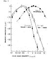
- Fig. 3 is a graph showing the relationship between the frame frequency and the color spatial frequency of the visual system converted using the above-mentioned equations (1), (2), and (3). Further, in the figure, (120, 0.4) is the one showing the present level of the projection type display device using the color sequence driving system, and (180, 0.5) or more, preferably (250, 0.6) or more, further preferably (300, 0.8) or more show the frame frequency levels to be used in the color display device of the present embodiment.
- the experimental apparatus shown in Fig. 4 is constituted of a light source 1 for emitting a white light, a RGB rotary filter 2 for spectra-generating RGB three colored lights from the light of the light source, a screen 3, and a chopper blade 4 for generating a retinal shifting rate.
- a R colored light, a G colored light, and a B colored light are generated sequentially by passing the white light emitted from the light source 1 through the RGB rotary filter 2, and these colored lights enter on the screen 3 from the rear. Then, the time spatial color band is generated by rotating the chopper blade 4 that is placed in front of the screen 3.
- the experimental apparatus of Fig. 5 is a configuration in which the light source 1 and the RGB rotary filter 2 that are the RGB colored lights generation means in Fig. 4 are replaced with the color sequence driving illumination system constituted of a dichroic prism 6, a R light source 5R, a G light source 5G, a B light source 5B, a red colored light selective reflection layer and a blue colored light selective reflection layer are formed in a X-letter shape, and mirrors 7 which reflect the red colored light and blue colored light from the R light source 5R and the B light source B to the prism 6 side.
- the respective light sources 5 are lit in sequence and from the dichroic prism 6 three colored lights are incident on the screen 3 in sequence from the rear.
- an arbitrary frame frequency can be set by making the switching of the lighting of the R light source 5R, the G light source 5G, the B light source 5B to be variable.
- Other structure and operations are the same as the ones of the experimental apparatus shown in Fig. 4. Further, in the experimental apparatuses of Figs. 4 and 5, they may be constituted with the order of the colors such as RGB, RBG, BGR and the like being changed.
- Fig. 6 is a graph showing the individual data
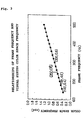
- Fig. 7 is a graph in which an average and a standard deviation are obtained based on the individual data.
- the psychological color breakup perceptions show different tendencies (2 phase property) with the retina shifting rates being roughly less than 300 deg/sec and 300 deg/sec or more, and a sharp start of a frame frequency is realized for the one with 300 deg/sec or more.
- eye movement there are four kinds: a following movement, an intermittence movement, a convergence/divergence movement, and an involuntary eye movement.
- the following movement is a low rate eye movement with about 30-35 deg/sec such as following a flying fly with an eye.
- the intermittence movement is an intermittent high speed jump movement, and is an eye movement to compensate a shifting rate of the subject beyond the rate of the following movement, that can be seen in a line of sight shifting at a time when reading a book, and is a high speed eye movement with 300 deg/sec or more. From these, it may be interpreted such that a retina shifting rate of 300 deg/sec is equivalent to the intermittent movement, and for the frame frequency it is sufficient to secure 250 Hz or more on the graph, but when taking the measurement accuracy and the individual differences of the subjects and the like into account, it is more preferable to secure 300 Hz or more.
- Figs. 8 and 9 which show the relationship between the frame frequency and the retina shifting rate obtained from the above-mentioned experiment, are graphs in which the frame frequency is inverted to the color discrimination threshold value of the visual system.
- the color discrimination threshold value of the visual system herein it is defined as the one in which the frame frequency obtained from the psychological color breakup threshold value that is perceived when a time spatial characteristic in the experiment is inverted to the physical RGB color band width that is simply spread out on the retina.
- Figs. 8 and 9 are the differences in the characteristics of the color discrimination threshold value of the visual system realized with the retina shifting rates of 50 - 200 deg/sec, 200 - 300 deg/sec, and 300 deg/sec or more.
- the eye movements that can be considered as relevant to these data are two kinds, namely the low rate following movement with about 30-35 deg/sec such as following the flying fly with an eye for example, and the high speed intermittent movement with 300 deg/sec or more that alertly captures the subject that is suddenly appeared intermittently as being separated and compensates the shifting rate of the subject beyond the rate of the following movement.
- the eye movement rates with 200 deg/sec or more and less than 300 deg/sec (equivalent to the retina shifting rates) of the independent variables (horizontal axis) of the data shown in Figs. 8 and 9 do not exist.
- the eye movement rates with 200 deg/sec or more and less than 300 deg/sec may be considered to exist as a movement with which the subject will shift on the retina, since in the presentation in which the projection type display device and the like are used, for example, there is an occasion that a presenter and/or an object that is moved by the presenter make(s) various kinds of actions in front of the screen in a state being seen from the observer of the display scene.
- the eye movement rates in the range being considered , the color sensitivity of the visual system of a person who watches the screen is lowered. From the above, it may be assumed that the retina shifting rates influence the change of the color discrimination threshold value of the visual system.
- the color display device As described above, directing attention to the range of the retina shifting rates (200 deg/sec or more and 300 deg/sec) in which the color sensitivity of the visual system is lowered, and making the frame frequency (color generation frequency) corresponding to the range of this retina shifting rates to be 180 Hz or more enables reduction or elimination of the psychological color breakup even if the presenter or the object performs the various kinds of actions in front of the screen.
- the frame frequency of the color display device is a frame frequency (color generation frequency) that satisfies the maximum rate of the eye movement that exists, i.e., it is 300 Hz or higher than 250 Hz, enables not only prevention of perception of the above-mentioned color breakup but also reduction or elimination of the perception of the psychological color breakup that occurs in the color sequence driving system.
- the color display device 10 of the present first embodiment since a phenomena in which the color breakup is perceived can be controlled, a high quality color display can be implemented on the screen. As a result, according to the present first embodiment, at a time when observing an image on the screen 16, an observer will not sense an incongruity in the image, and thus this enables the display of an excellent color image, with less fatigue to the observer. Moreover, in the color display device 10 of the present first embodiment, since a color display can be implemented with a single electro-optic device (modulator) 14, i.e., it is applicable to the projection type display device of a single plate system, a light weight projector and lower cost can be obtained.
- module electro-optic device
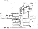
- Fig. 10 shows a second embodiment of the color display device and a color display method according to the present invention.
- the present embodiment is one in which the present invention is applied to a direct viewing color display device constituted of an illumination device.
- the present embodiment is one in which the repetition frequency (frame frequency) of three colored lights that are emitted from the rear side of the screen is controlled so as to be 250 Hz or more, preferably 300 Hz or more, and a timing of a color image generation in the electro-optic device as the image generation unit is set to be matched with the generation timing of the respective colored lights.
- the color display device 100 of the present second embodiment comprises an illumination light source 101 in which a color switching type back-light is used, an electro-optic device 102, and a driving circuit for driving and controlling the color switching type back-light illumination light source 101 and the electro-optic device 102.
- the illumination device since the illumination device is of the back-light type, it is arranged as a transmission type electro-optic device, and thus it would be better to use a transmission type liquid crystal display device, for example.
- a configuration of the color switching type illumination light source 101 comprises, for example, a red light emitting light source, a green light emitting light source, and a blue light emitting light source (not shown), arranged to uniformly irradiate the colored lights emitted therefrom onto a display zone of the transmission type electro-optic device 102 through a light guide plate (not shown), for example.
- each of the light sources it is possible to apply various kinds of light emitting source of colored lights, such as a fluorescent tube e.g., a cold-cathode tube, a hot-cathode tube, an EL (Electroluminescence) light-emitting device, a LED and the like.
- a fluorescent tube e.g., a cold-cathode tube, a hot-cathode tube, an EL (Electroluminescence) light-emitting device, a LED and the like.
- the electro-optic device 102 selected to be a reflective type electro-optic device a configuration in which the light guide plate is placed on a front side thereof or the illumination light source is placed on the side thereof may be used as the illumination light source 101.
- a structure using the reflective type electro-optic device 102 is the same as the constitution described in the first embodiment.
- a liquid crystal display device in which a monochrome display is implemented without using a color filter similar to the first embodiment, can be used.
- various kinds of liquid crystal display devices having high speed response for example, such as a liquid crystal panel of ⁇ cell mode, a liquid crystal panel in which a cell gap of the TN liquid crystal is set to be narrowed, and a liquid crystal panel of the OCB mode and the like can be applied.
- the driving circuit 103 comprises a microprocessor 104, a timing generator 105, a frame memory 106, a driving control circuit 107, a light source switcher 108, and a light source power supply 109.
- the switching timing of the light source color switcher 108 and the driving timing of the electro-optic device 102 are controlled by the timing generator 105.
- an image signal is sampled with a sampling circuit which is not shown in the figure.
- a synchronizing signal in the image input signal is sent to the microprocessor 104 and to the timing generator 105.
- an image data in the image signal be written into the frame memory 106 with a timing that is controlled by the timing generator 105.
- the color switching type illumination light source 101 is controlled by the light source color switcher 108 and the timing generator 105 so as to be synchronized with the driving timing of the respective color images of the electro-optic device 102.
- a red light emitting light source, a blue light emitting light source, and a green light emitting light source (not shown in the figure) are lit repetitively in a time sequence.
- the colored lights are generated in the color sequence corresponding to the display data color.
- the colored lights (lights for use in the display) of the respective colors irradiated as such, are implemented with a light modulation by the transmission type electro-optic device 102, and then a color image display is implemented in the color sequence.
- a light switching timing signal is supplied to the light source color switcher 108 from the timing generator 105, and for the selected light source a power supply is supplied from the power supply for use in light source 109, and then the light source of the red colored light is lit.
- a read-timing signal is supplied to the frame memory 106 from the timing generator 105, the image data of the red component that is stored in advance during the driving period prior to the present is read sequentially, and the driving control circuit 107 which receives that image data drives each of pixels of the electro-optic device 102 in response to the image data for use in the red component.
- the timing generator 105 implements a timing-control so as to synchronize the timing of the respective elements upon receiving a control from the microprocessor 104.
- the electro-optic device 102 is a modulation element which is constituted of a liquid crystal panel as described above, and in which pixels constituted of pixel electrodes are arranged in a matrix, and a red colored light is modulated for each pixel, and then an image of the red colored light is generated. Accordingly, an image is displayed on the display screen by the red colored light of which a light intensity is modulated for each pixel.
- the electro-optic device 102 is a transmission type liquid crystal panel
- the liquid crystal material is sandwiched between a pair of substrates, having a transparent pixel electrode for each pixel in the substrate on the opposite side.
- An effective voltage is applied to a liquid crystal layer from this pixel electrode in response to the image data.
- light is emitted by changing a plane of polarization and/or a scattering angle of the incident light in response to a change in an array of the liquid crystal molecules in the liquid crystal layer.
- the plane of polarization entering an incident light through a polarization element, displaying a reflected light through the polarization element, the light intensity is modulated for each pixel.
- a change of light scattering in the case that the liquid crystal is of the high polymer dispersion type
- light intensity is modulated for each pixel in accordance with the degree of scattering, so that the polarization element is no longer necessary.
- a color display device for generating an image using a reflective type electro-optic device comprising a reflective type liquid crystal panel
- the pixel configuration is similar to the one described in the first embodiment.
- the use of a reflective type liquid crystal panel enables a memory (frame memory 106) for each pixel, and a driving control circuit 107 for supplying a voltage to the pixel electrode in response to the memory content thereof, to be installed below the reflective type image electrode.
- a repetition frequency (frame frequency) of the three colored lights of the illumination light source is switching controlled by the timing generator 105 at 250 Hz or more, preferably 300 Hz or more. Also, a timing of a color image generation in the electro-optic device 102 is set so as to be matched with a generation timing of the respective colored lights.
- Fig. 11 shows a projection type display device as a color display device of the present invention.
- the present embodiment differs from the first embodiment in that the electro-optic device 14 of the first embodiment is replaced with the transmission type electro-optic device 204.
- Other points of configuration and operation are the same as in the first embodiment.
- the projection type display device 200 of the present embodiment comprises a light source 201 for emitting a white light including the respective spectra of a red colored light, a blue colored light and a green colored light, a rotary color filter 202 being disposed in front of the light source 201 and having areas of color elements for the red, blue and green, a transmission type electro-optic device 204 disposed in front of the rotary color filter 202 for generating a color image corresponding to the color of the incident light, and a projection lens 205 for projecting light that is modulated / reflected in the electro-optic device 204, and an image is displayed as an image generation colored light being projected from the projection lens 205 onto a screen 206.
- the light source 201 is provided with a reflector 201a for reflecting light from the light source as shown.
- an observer who watches an image projected onto the screen 206 might watch the projected image by being situated in front of the screen 206 if the color display device is a front projection type, or might be situated at the rear of the screen 206 if the color display device is a rear projection type.
- a presenter human being stands in front of the screen 206, as viewed from the observer, and describes by pointing out the projected display screen, using an object such as a finger or an indication stick. Accordingly, from the view point of the observer, an action of the presenter or the object in front of the screen 206 blocks the display screen.
- various kinds of modulators having a high-speed response such as a ferroelectric liquid crystal panel, an antiferroelectric liquid crystal panel, a liquid crystal panel of a ⁇ cell mode, a liquid crystal panel in which a cell gap of a TN liquid crystal cell is set to be narrowed, and a liquid crystal panel of a OCB mode and the like such as a reflective type liquid crystal light valve, can be used.
- the projection type display device 200 mainly comprises a driving circuit 211 constituted of a microprocessor 207, a timing generator 208, a frame memory 209, and a driving control circuit 210.
- This projection type display device 200 is controlled by synchronizing a rotary drive of the rotary color filer 202 and a driving timing of the transparent type electro-optic device 204 with the timing generator 208.
- an image signal is sampled with a sampling circuit(not shown in the figure).
- a synchronizing signal in the image input signal is sent to the microprocessor 207 as well as the timing generator 208.
- the white light emitted from the light source 201 passes through the three-color rotary color filter 202 that rotates in synchronization with the driving timing of the electro-optic 204 by the timing generator 208.
- the colored lights are generated sequentially as red light, a blue light, and a green light from the light source, and then are irradiated onto the electro-optic device 204.
- a light modulation is implemented by passing through the electro-optic device 204.
- the image is enlarged and projected by the projection lens 205, and is image-formed on the screen 206 so as to implement a color image display.
- the timing generator 208 implements a timing-control so as to synchronize the timing of the respective elements upon receiving a control signal from the microprocessor 207.
- the electro-optic device 204 is a modulation element which is constituted of a liquid crystal panel, and in which pixels are arranged in a matrix, and red light is modulated by the pixels, and then a red colored image is generated. Accordingly, a red colored light of which the light intensity is modulated for each pixel is incident on the projection lens 205, and an image of a red colored light is projected and displayed on the screen 206.
- the image data for use in the blue colored light is read from the frame memory 209.
- each pixel of the electro-optic device 204 is driven in response to the image data thereof, a blue colored light is modulated, and an image of a blue colored light is projected and displayed on the screen 206.
- the timing with which the light from the light source passes through the green zone of the rotary color filter 202 the same operation is effected.
- images of three colored lights are generated sequentially with the electro-optic device 204, and by repeating this cyclicly, a color image is displayed. Further, the order of generating the colored lights is not limited to the present embodiment. It may be any order.
- a repetition frequency (frame frequency) of three colored lights generated by the number of rotations of the rotary color filer 202 is controlled by the timing generator 208 to be 180 Hz or more, preferably 250 Hz or more, further preferably 300 Hz or more. Also, the timing of color image generation in the electro-optic device 204 is set so as to match with a generation timing of the respective colored lights.
- the display for reducing the color identification sensitivity of the visual system can be implemented.
- the display for reducing the color identification sensitivity of the visual system can be implemented.
- an eye movement caused by an action of a presenter who performs a presentation by standing in front of the screen 206 or a finger or an object such as an indication stick moved by the presenter occurs, it is possibly to reduce or eliminate color breakup being perceived.
- an excellent presentation can be made without any sense of incongruity in the color display image. Accordingly, in the present embodiment, it is possible to provide an excellent color image without giving the fatigue to the observers.
- the present invention is applicable to the various kinds of color display device such as a projection type display device using a transmission type light valve, and a reflective type display device having the light sources in front of the display screen or at the side thereof, and the like.
- a plurality of colored lights to be generated are described with respect to the three colored lights of red colored light, blue colored light and green colored light, but they may be the three colored lights of cyan light, magenta light and yellow light, or they may be two colored lights or may be a switching of multi-colored lights of more than three colors.
- each of the colored lights is generated, but as in the color sequence driving illumination system of Fig. 5, there may instead be provided a plurality of light sources (a light source of red colored light, light source of green colored light, and a light source of the blue colored light) that generate each of the plurality of colored lights separately, with colored light being generated by sequentially selecting the light source to be lit according to the sequence timing generator (18, 208).
- a plurality of light sources a light source of red colored light, light source of green colored light, and a light source of the blue colored light
- the repetition frequency for generating the plurality of colored lights to be 180 Hz or more, preferably 250 Hz or more, and further preferably 300 Hz or more, it is possible to reduce or control the color breakup phenomena.
- the present invention provides a color display method and a color display device of a time-division driving system, in which the perception of color breakup caused by an action performed by a presenter, as well as the perception of the color breakup caused by eye movements are avoided.
Abstract
The color display device includes a colored light generation unit for repetitively
generating a plurality of colored lights in a time sequence with a predetermined
frequency, and an image generation unit for processing said plurality of colored lights,
so as to generate an image corresponding to each of said plurality of colored lights in a
time sequence, wherein said predetermined frequency is 180 Hz or more.
Description
- The present invention relates to a color display device for and a color display method of implementing a color image generation as being time-division driven.
- Recently, as a color display device, attention has been directed to a device which implements a color display with an additive mixture of color stimuli according to a time difference color mixture, i.e., a time division driving system within a single dot. In such a color display device, because one pixel becomes one picture element, there is an advantage that a threefold resolution compared to the color display device that implements a juxtaposition color mixture can be obtained. As one of the color display devices of the time division driving system such as described above, there is known a DMD projector which displays a color image by irradiating colored lights of R (Red), G (Green), and B (Blue) that are generated by being passed through a color filter disk which rotates a light from a white color light source onto an array of a digital micro-mirror device arrays (DMD: e.g., a device developed by Texas Instruments Incorporated) in a time sequence and by projecting the colored lights modulated/reflected with this DMD array onto a screen. Further, other than the above, there is a color liquid crystal display device and the like in which the color light source for generating the colored lights of R, G, B is arranged behind the liquid crystal panel that implements a black and white display.
- However, in the color display devices such as the DMD projector and the color liquid display device, which are time-division driven as described above, when an eye (or eyes) of an observer follows the subject image that crosses over a screen or a display, for example, it has a problem that the observer perceives a color separation. As a result, there is a problem that a color displacement occurs on the observed image and thereby deteriorating a display quality.
- In addition, in the case of the projection type display device that is time-division driven (i.e., a DMD projector and a liquid crystal projector), there is a problem that an observer perceives a color separation as being caused by an action that is to be conducted by a presenter situated in front of a screen for example, indicating on the screen with an indication stick or a finger and an action of crossing over in front of the screen. Accordingly, there is a problem such that a color displacement occurs on the observed image thereby deteriorating a display quality, and the observer perceives a feeling of fatigue and the like. Further, it has been reported that a similar perception of a color display also occurs in an image pickup device.
- In general, when watching an image generated by the color display device of the time-division driving system, it is known that the color band of the colored lights of R (Red), G (Green), B (Blue) are formed physically on a retina (or retinas) by an eye movement occurring voluntarily or involuntarily, and caused thereby is a phenomena (hereinafter, it is referred to as a color breakup) in which a color separation is perceived psychologically.
- Now, it is described about the color breakup that is generated by the eye movement of human beings. Fig. 12 shows a mechanism with which the color band of RGB colored lights are formed physically on the retina by the eye movement which occurs voluntarily or involuntarily, at a time when seeing the RGB original image that is created by driving three colored lights in a time sequence (hereinafter, it is referred to as a color sequence). In the color display device that is time-division driven, by synchronizing-signal processing the respective RGB colored lights and the images corresponding thereto, a R image, a G image, and a B image are generated without any phase displacement spatially. A human being recognizes the respective color images of these RGB as the color images that are equivalent to the original images by additive mixing of color stimuli time-integrally with a visual center of higher order. However, during the image observation in practice, human beings experiences a line of sight shift and blink unconsciously or consciously. At that moment, the respective images of RGB that are generated time-integrally by the color sequence driving are influenced spatially with the eye movements, and the color band of RGB is formed physically on the retina as shown in Fig. 12. This is perceived as color breakup within the visual center of higher order.
- In the following, with reference to Fig. 13, an actual model (time-space integral type additive mixture of color stimuli) and an ideal model (time integral type additive mixture of color stimuli) of the color images that are generated on the retina by the color sequence driving are described in comparison. In the figure, a vertical axis represents time and a horizontal axis represents space. Further, although the figure shows the three-frame images, in the color image with the color sequence driving, it is a system which color-composes the R image, the G image, the B image that are generated on the retina with a time-difference determined uniquely by the frame frequency within the visual center of higher order. Accordingly, as shown on the left side in the figure, the R image, the G image, the B image (for example, AR image, AG image, AB image) that form one frame are generated on the retina with the time-difference that is determined uniquely by the frame frequency, but this would be an ideal as no displacement occurs spatially. However, as the eye movement participates in practice, as shown on the right side in the figure, a time-difference in which the R image, the G image, the B image (for example, AR image, AG' image, AB' image) that form one frame are determined uniquely by the frame frequency, and a spatial position displacement that is determined uniquely by the eye movement rate are generated on the retina simultaneously. This phenomena occurs only when the eye movement is generated, and it does not occur at a time when the eyeball is in a stationary state or is in a relative stationary state (for example, in a state as following a movement of a fly). Further, this is such that a generation situation differs depending on the direction of the eye movement (for example, the AR image, AG' image, AB' image that are the first frame on the right side of Fig. 13, and the CR image, CG' image, CB' image that are the third frame thereof are such that their generation directions thereof are reversed).
- As described above, in the color display device of the time-division driving system (color sequence driving system), it is fundamental to color generation to assume the time integral type additive mixture of color stimuli, but as the eye movement disproves this assumption, the fundamental (ideal) is no longer established, and there will be a perception problem of a psychological color breakup such as described above. Fig. 14 is an illustrative drawing showing a color image generation model according to a combination of the color sequence driving system as such and a visual system. As can be seen from the figure, in the color image generation according to the color sequence driving system, it is required to develop a color display device by considering the eye movement of the
human factor 1 and the psychological color breakup perception of thehuman factor 2. Particularly, in the projection type display device, upon considering these human factors, it will be an object to control a generation of the color breakup that is perceived as being caused by an action and the like performed by a presenter who performs a presentation such as when standing in front of a screen. - It is realized that such color breakup is configured as to be not perceived by physically narrowing the width of the color band by contracting the time difference of the three colored lights by increasing the frame frequency to be about 2000 Hz - 3000 Hz, but for the frame frequency of about 120 Hz in the present situation, the image generation drive and the color generation drive with the higher frame frequency such as 2000 Hz - 3000 Hz are difficult in practice.
- The present invention is made in light of the above-mentioned problems, and an object of the present invention is to provide a color display device of a time-division driving system and a color display method thereof, in which there occurs no perception of a color breakup being caused by an action performed by a presenter, as well as perception of a color breakup being caused by an eye movement.
- The color display device of the present invention comprises a colored light generation unit for repetitively generating a plurality of colored lights in a time sequence with a predetermined frequency and an image generation unit for processing the plurality of colored lights, so as to generate an image corresponding to each of the plurality of colored lights generated in a time sequence, wherein the predetermined frequency is 180 Hz, thereby the above-mentioned object can be achieved.
- Preferably, the predetermined frequency is 250 Hz.
- More preferably, the predetermined frequency is 300 Hz.
- In some aspects of the embodiments, the colored light generation unit comprises a light source, and a color filter for generating the plurality of colored lights from light coming from the light source.
- In other aspects of the embodiments, the colored light generation unit comprises a plurality of light sources for emitting colored lights different from each other, wherein the plurality of light sources turn on in a time sequence.
- In some aspects of the embodiments, the image generation unit is a reflective type electro-optic device, according to any of the color display devices in claims 1 - 5.
- In further aspects of the embodiments, the electro-optic device is a liquid crystal device.
- In further aspects of the embodiments, the electro-optic device is a digital micro-mirror device.
- In further aspects of the embodiments, the image generation unit comprises a transmission-type electro-optic device.
- In further aspects of the embodiments, the color display device further comprises a lens for projecting the image.
- A color display method of the present invention comprises a colored light generation step for repetitively generating a plurality of colored lights in a time sequence with a predetermined frequency and an image generation step for processing the plurality of colored lights, so as to generate an image corresponding to each of the plurality of colored lights generated in a time sequence, wherein said predetermined frequency is 180 Hz, thereby the above-mentioned object can be achieved.
- Preferably the predetermined frequency is 250 Hz.
- More preferably, the predetermined frequency is 300 Hz.
- According to the present invention, by setting a repetition frequency range of the colored lights in which a color identification in a visual system is lowered, for example, enables control or prevention of color breakup that is caused by an action of a presenter who performs a presentation such as when standing in front of a screen or an object in front of the screen. Further, it also enables prevention of color breakup that is caused by an eye movement of an observer. In addition, it enables driving with a repetition frequency in a practical range without drastically increasing the repetition frequency of the colored light generation of the color display device of the time-division driving system. As a result, according to the present invention, a person who watches a displayed image on a screen no longer has a sense of an incongruous image, and it has an advantage of enhancing a quality of an observed image while reducing a sense of fatigue accompanied by the image observation.
-
- Fig. 1 is an illustrative drawing showing the first embodiment of the color display device according to the present invention;
- Fig. 2 is a graph showing visual color spatial frequency characteristics;
- Fig. 3 is a graph showing a relationship between frame frequency and color spatial frequency of a visual system;
- Fig. 4 is an illustrative drawing showing an experimental arrangement to obtain a relationship between a retina shifting rate and a frame frequency;
- Fig. 5 is an illustrative drawing showing an alternative example of the experimental arrangement to obtain a relationship between retina shifting rate and frame frequency;
- Fig. 6 is a graph showing optimal frame frequency characteristics of a visual system;
- Fig. 7 is a graph showing optimal frame frequency characteristics of a visual system;
- Fig. 8 is a graph showing color discrimination threshold value characteristics of a visual system;
- Fig. 9 is a graph showing color discrimination threshold value characteristics of a visual system;
- Fig. 10 is an illustrative drawing showing a second embodiment of the color display device according to the present invention;
- Fig. 11 is an illustrative drawing showing a third embodiment of the color display device according to the present invention;
- Fig. 12 is an illustrative drawing showing a mechanism with which a color band is formed on a retina by an eye movement;
- Fig. 13 is an illustrative drawing showing a color image generation model with a color sequence driving system; and
- Fig. 14 is an illustrative drawing showing a color image generation model with a combination of a color sequence driving system and a visual system.
-
- Details of the color display device and the color display method of the present invention will be described based on the embodiments shown in the drawings.
- Fig. 1 shows a first embodiment of a color display device and a driving method of the color display device according to the present invention. As shown in the figure, the
color display device 10 of the present embodiment is a color display device that comprises alight source 11 for emitting a white light including the respective spectra of a red colored light, a blue colored light and a green colored light, arotary color filter 12 being disposed in front of thislight source 11 and having areas of color elements for red, blue and green, acondenser lens 13 being disposed in front of therotary color filter 12, an electro-optic device 14 for generating a color image corresponding to a color of a colored light incident through thecondenser lens 13, and aprojection lens 15 for performing a projection upon receiving a light that is reflected/modulated in the electro-optic device 14, and an image is displayed as an image generation colored light being projected from theprojection lens 15 onto ascreen 16. In thelight source 11, there is provided a reflector 11a for reflecting a light from the light source as shown. - An observer who watches an image projected onto the screen might watch the projected image by being situated in front of the
screen 16 if the color display device is a front projection type, or by being situated at the rear of thescreen 16 if the color display device is a rear projection type. In a presentation using a color display device, a presenter (human being) stands in front of thescreen 16 as being viewed from the observer, and describes by pointing out the projected display screen, using an object such as a finger or an indication stick. Accordingly, in from the view point of the observer, an action of the presenter or the object in front of thescreen 16 is performed as blocking the display screen. Conventionally, a color breakup phenomenon occurs as a result of this action. - One of the advantages of the present invention is to solve a perception problem of a conventional color breakup and a detailed configuration for this will be described below.
- As the above-mentioned electro-
optic device 14, various kinds of modulators having a high-speed response, such as a ferroelectric liquid crystal panel, an antiferroelectric liquid crystal panel, a liquid crystal panel of a π cell mode, a liquid crystal panel in which a cell gap of a TN liquid crystal cell is set to be narrowed, and a liquid crystal panel of a OCB mode and the like as a DMD array, or a reflection type liquid crystal light valve, can be applied thereto. - Further, the
color display device 10 as such mainly comprises a drivingcircuit 21 constituted of amicroprocessor 17, atiming generator 18, aframe memory 19, and a drivingcontrol circuit 20. Thiscolor display device 10 is controlled by synchronizing a rotary drive of therotary color filer 12 and a driving timing of the reflection type electro-optic device 14 with thetiming generator 18. First, an image signal is sampled with a sampling circuit which is not shown in figure. Then, a synchronizing signal in the image input signal is sent to themicroprocessor 17 as well as thetiming generator 18. At the same time, it is arranged that an image data in the image signal is written into theframe memory 19 with a timing that is controlled by thetiming generator 18. It is arranged that the white light emitted from thelight source 11 passing through the three-colorrotary color filter 12 that rotates in synchronization with the driving timing of the electro-optic 14 by thetiming generator 18 generates colored lights by sequentially passing through a red light, a blue light, and a green light and then irradiated onto the reflection type electro-optic device 14 through thecondenser lens 13. For each of the colored lights irradiated as such, a light modulation is implemented and is enlarged and projected by theprojection lens 15, and then an image is formed on thescreen 16 so as to implement a color image display. - For example, for synchronizing with a timing with which the light from the
light source 11 passes through a red zone of therotary color filter 12, in response to reading timing signal supplied from thetiming generator 18, the image data of the red component that is stored in advance during the driving period prior to the present is read sequentially, from theframe memory 19, and the drivingcontrol circuit 20 which receives that image data drives each of pixels of the electro-optic device 14 in response to the image data for use in the red component. Thetiming generator 18 implements a timing-control so as to synchronize the timing of the respective elements upon receiving a control signal from themicroprocessor 17. The electro-optic device 14 is a modulation element which is constituted of a DMD or a liquid crystal panel as described above, and in which pixels constituted of reflection mirrors and/or reflection electrodes are arranged in a matrix. Red light is reflected for each pixel, a modulation is made with this reflection, and then a red colored image is generated. Accordingly, a red colored light of which the light intensity is modulated for each pixel is incident on theprojection lens 15, and an image of a red colored light is projected and displayed on thescreen 16. - Then, with a timing with which the light from the light source passes through a blue zone of the
rotary color filter 12, similar to the case of the red colored light, the image data for use in the blue colored light is read from theframe memory 19. In response thereto, each pixel of the electro-optic device 14 is driven in response to the image data thereof, a blue colored light is modulated, and an image of a blue colored light is projected and displayed on thescreen 16. Then, with a timing with which the light from the light source passes through a green zone of therotary color filter 12, it is the same as above. As described above, images of three colored lights are generated sequentially with the electro-optic device 14, and by repeating this, a color image is displayed. Further, an order of generating the colored lights is not limited to the present embodiment. It may be any order. - Herein, when the electro-
optic device 14 is a DMD, the DMD modulates a quantity of light incident on theprojection lens 15 by changing a tilt angle of the reflection mirror in response to the image data for each pixel. More concretely, it is arranged to enable pulse-width modulation (PWM) of a time width to direct the light reflected from the reflection mirror to theprojection lens 15 and a time width to cause the light reflected to be absorbed into an absorber in response to the image data, and to modulate the intensity of colored lights for each pixel. Further, in the case of the DMD, it makes it possible to implement theframe memory 19 in the electro-optic device as a SRAM, and having an image memory for each pixel, and in response to a memory content thereof, it makes it possible to cause a reflection mirror for each pixel to be angle-module-driven by the drivingcontrol circuit 20 that is installed for each pixel. These memories and driving control circuits are disposed under the reflection mirrors. Furthermore, when the electro-optic device 14 is a liquid crystal panel, the liquid crystal illustrated previously is sandwiched between a pair of substrates, having a pixel electrode for each pixel in the substrate on the opposite side, and changing an effective voltage that is applied to a liquid crystal layer from this pixel electrode in response to the image data, then reflecting/emitting by changing a plane of polarization and/or a scattering angle of the incident light in response to a change in an array of the liquid crystal molecules in the liquid crystal layer. By changing the plane of polarization, by entering an incident light through a polarization element and directing a reflected light to theprojection lens 15 through the polarization element, light intensity is modulated for each pixel. By a change of light scattering (in the case that the liquid crystal is a high polymer dispersion type), by providing a slit before theprojection lens 15 and causing light to pass through it, similar to the DMD, light intensity is modulated for each pixel. Also when the liquid crystal panel is similar to the DMD, it makes it possible to install, under the reflection type pixel electrode, the memory (frame memory 19) and the drivingcontrol circuit 20 that applies a voltage to a pixel electrode in response to a memory content thereof for each pixel. - The
color display device 10 of the present embodiment has a reflective type electro-optic device as the electro-optic device 14, but when using a liquid crystal device (liquid crystal panel), it may have a transmission type electro-optic device including a transmission type liquid crystal panel as the electro-optic device 14. - In the present embodiment, a repetition frequency (frame frequency) of the three colored lights of the
rotary color filer 12 is the number of rotations controlled by thetiming generator 18 to be 180 Hz or more, preferably 250 Hz or more, further preferably 300 Hz or more. Also a timing of color image generation in the electro-optic device 14 is set so as to be matched with a generation timing of the respective colored lights. - In an aspect of the present embodiment, by performing a color sequence driving with a frame frequency of 180 Hz or more, even if an eye movement is caused by an action of a presenter who performs a presentation when standing in front of the
screen 16 by moving a finger or an object such as an indication stick, the perceived color breakup is reduced or eliminated. Performing a color sequence driving with a frame frequency of 250 Hz or more, enables not only prevention of a perception of the above-mentioned color breakup along with the movement of the presenter but also reduction or elimination of color breakup caused by a high speed eye movement (to be described later) of an observer. In this case, taking the individual differences in the perceptions of the observers into an account, it is more preferable to perform the color sequence driving with a frame frequency of 300 Hz or more. - Now, the reasons for reduction or elimination of a perception of color breakup in the present embodiment will be described based on the relationship between the frame frequency and the color spatial frequency of the visual system.
- First, referring to Fig. 2, the relationship between the color spatial frequency of the visual system and the contrast (relative sensitivity) will be described. The figure is a known data described on "Television", 1977, vol. 31, No. 1, page 31. The horizontal axis of the graph in the figure indicates the color spatial frequency, and is represented in cycle/degree (cpd). A unit (cpd) of this color spatial frequency indicates the number of sine waves in a
visual angle 1 degree, and if there is 1 cycle of a sine wave in thevisual angle 1 degree it is said to be 1 cpd, and if there are 5 cycles of a sine wave in thevisual angle 1 degree it is said to be 5 cpd. Further, the vertical axis of this graph indicates the contrast sensitivity with the relative sensitivity (dB), and obtains the limit values of which a brightness discrimination and/or a color discrimination can not be performed. As shown in Fig. 2, in general, in a visual system of a human being, a sensitivity characteristic for the brightness (light and dark) is that a contrast sensitivity characteristic is poor even when the spatial frequency is low or high, and a contrast sensitivity of a bright ness is most pronounced around 4 cpd at the middle. Further, although not shown in figure, a cutoff frequency of the contrast sensitivity characteristic for this brightness is 60 cpd. On one hand, the sensitivity characteristic for the color similarly is also such that a contrast sensitivity characteristic is poor even when the spatial frequency is low or high, and a contrast sensitivity of the color is most pronounced around 0.4 cpd that is the chromaticity spatial frequency at the middle. 0.4 cpd is a result corresponding to a frame frequency of 120 Hz, and it can be said to be the worst condition from the view point of the color sequence driving system of which the human characteristic is taken into an account (in the projection type display device at the present time, there is known a device with a frame frequency of 120 Hz and in which color breakup is easily perceived). Further, not shown in the figure, a cutoff frequency of the sensitivity characteristic for this color is 4 - 10 cpd. - In order to reduce or eliminate color breakup, based on the known data as shown in Fig. 2, it is understood that providing a color spatial frequency of more than 0.4 cpd is required. The inventors of the present invention have found that providing a color spatial frequency of 0.5 cpd or more, enables reduction and/or elimination of a generation of color breakup that is caused by an action of a person or an object that is located in front of the
screen 16. Furthermore, preferably, providing the color spatial frequency with 0.8 cpd or more, that is twice 0.4 cpd, enables not only prevention of perception of the above-mentioned color breakup, but also reduction or elimination of occurrence of color breakup caused by a high speed eye movement. - An exchange between the frame frequency and the color spatial frequency (the spatial frequency of the visual system) can be made using the following equations (1), (2) and (3).
- Where Ft is a frame frequency (Hz), and is a frequency at a time when generating 1 frame of a color image (1 scene of color). Cba is a color band visual angle (degree) that is formed by each of the colored lights in which a color band width of 1 colored light is given by a visual angle. Further, the color band is the R band, G band, and B band formed on the retina, when using the RGB colored lights. A visual angle is uniquely determined by a reference point (a coupling point) of an eyeball and a band width of 1 colored light that is formed on the retina (no visual distance dependency). Rv is an eyeball circle movement rate (degree/second), and is an angular velocity of movement of a line of sight from a certain point to other point. An image projected on the retina on the inner surface of an eyeball moves with the same angular velocity (eyeball circle movement rate) as this line of sight movement. Accordingly, the eyeball circle movement rate and the retina shifting rate (retinal velocity) are equivalent. Vf is a color spatial frequency of the visual system (cycle/degree), and represents how many cycles of the RGB color band will be formed in the
visual angle 1 degree. For example, if 1 color band of the RGB is formed respectively in thevisual angle 1 degree, it becomes 1 cycle/degree (cpd), if 5 color bands are formed respectively, then it becomes 5 cpd. This is commonly used as an index for indicating a resolution in general, and in narrowing the band width, the color discrimination (identifying discrimination of color), and the luminance discrimination (light and dark discrimination of the brightness) are reduced. - Fig. 3 is a graph showing the relationship between the frame frequency and the color spatial frequency of the visual system converted using the above-mentioned equations (1), (2), and (3). Further, in the figure, (120, 0.4) is the one showing the present level of the projection type display device using the color sequence driving system, and (180, 0.5) or more, preferably (250, 0.6) or more, further preferably (300, 0.8) or more show the frame frequency levels to be used in the color display device of the present embodiment.
- In the following there is described, using the experimental apparatuses shown in Figs. 4 and 5, a method of obtaining the relationship between the retina shifting rate (retinal velocity) and the frame frequency.
- The experimental apparatus shown in Fig. 4 is constituted of a
light source 1 for emitting a white light, aRGB rotary filter 2 for spectra-generating RGB three colored lights from the light of the light source, ascreen 3, and achopper blade 4 for generating a retinal shifting rate. In this experimental apparatus, temporally a R colored light, a G colored light, and a B colored light are generated sequentially by passing the white light emitted from thelight source 1 through theRGB rotary filter 2, and these colored lights enter on thescreen 3 from the rear. Then, the time spatial color band is generated by rotating thechopper blade 4 that is placed in front of thescreen 3. An observer will fixate a predetermined one point on thescreen 3 from a constant distant, and the color band is image-formed on the retina. Then, a psychological color breakup perception is judged by a subjective evaluation. Moreover, by making the rotational rate of theRGB rotary filter 2 to be variable, an arbitrary frame frequency can be set, and by making the rotational rate of thechopper blade 4 placed in front of thescreen 3 to be variable, an arbitrary retina shifting rate can be set. - The experimental apparatus of Fig. 5 is a configuration in which the
light source 1 and theRGB rotary filter 2 that are the RGB colored lights generation means in Fig. 4 are replaced with the color sequence driving illumination system constituted of adichroic prism 6, aR light source 5R, a Glight source 5G, a Blight source 5B, a red colored light selective reflection layer and a blue colored light selective reflection layer are formed in a X-letter shape, and mirrors 7 which reflect the red colored light and blue colored light from theR light source 5R and the B light source B to theprism 6 side. Therespective light sources 5 are lit in sequence and from thedichroic prism 6 three colored lights are incident on thescreen 3 in sequence from the rear. In this experimental apparatus, an arbitrary frame frequency can be set by making the switching of the lighting of theR light source 5R, the Glight source 5G, the Blight source 5B to be variable. Other structure and operations are the same as the ones of the experimental apparatus shown in Fig. 4. Further, in the experimental apparatuses of Figs. 4 and 5, they may be constituted with the order of the colors such as RGB, RBG, BGR and the like being changed. - The relationship between the retina shifting rate and the frame frequency that are obtained from the results for two subjects using these experimental apparatuses are shown in Figs. 6 and 7. Fig. 6 is a graph showing the individual data, and Fig. 7 is a graph in which an average and a standard deviation are obtained based on the individual data.
- As can be seen from Figs. 6 and 7, the psychological color breakup perceptions show different tendencies (2 phase property) with the retina shifting rates being roughly less than 300 deg/sec and 300 deg/sec or more, and a sharp start of a frame frequency is realized for the one with 300 deg/sec or more. With respect to eye movement, there are four kinds: a following movement, an intermittence movement, a convergence/divergence movement, and an involuntary eye movement. The following movement is a low rate eye movement with about 30-35 deg/sec such as following a flying fly with an eye. The intermittence movement is an intermittent high speed jump movement, and is an eye movement to compensate a shifting rate of the subject beyond the rate of the following movement, that can be seen in a line of sight shifting at a time when reading a book, and is a high speed eye movement with 300 deg/sec or more. From these, it may be interpreted such that a retina shifting rate of 300 deg/sec is equivalent to the intermittent movement, and for the frame frequency it is sufficient to secure 250 Hz or more on the graph, but when taking the measurement accuracy and the individual differences of the subjects and the like into account, it is more preferable to secure 300 Hz or more.
- Figs. 8 and 9, which show the relationship between the frame frequency and the retina shifting rate obtained from the above-mentioned experiment, are graphs in which the frame frequency is inverted to the color discrimination threshold value of the visual system. Further, although there is no general definition for the color discrimination threshold value of the visual system, herein it is defined as the one in which the frame frequency obtained from the psychological color breakup threshold value that is perceived when a time spatial characteristic in the experiment is inverted to the physical RGB color band width that is simply spread out on the retina.
- Of note from the graphs of Figs. 8 and 9 are the differences in the characteristics of the color discrimination threshold value of the visual system realized with the retina shifting rates of 50 - 200 deg/sec, 200 - 300 deg/sec, and 300 deg/sec or more. The eye movements that can be considered as relevant to these data are two kinds, namely the low rate following movement with about 30-35 deg/sec such as following the flying fly with an eye for example, and the high speed intermittent movement with 300 deg/sec or more that alertly captures the subject that is suddenly appeared intermittently as being separated and compensates the shifting rate of the subject beyond the rate of the following movement. Moreover, in general, the eye movement rates with 200 deg/sec or more and less than 300 deg/sec (equivalent to the retina shifting rates) of the independent variables (horizontal axis) of the data shown in Figs. 8 and 9 do not exist. However, the eye movement rates with 200 deg/sec or more and less than 300 deg/sec may be considered to exist as a movement with which the subject will shift on the retina, since in the presentation in which the projection type display device and the like are used, for example, there is an occasion that a presenter and/or an object that is moved by the presenter make(s) various kinds of actions in front of the screen in a state being seen from the observer of the display scene. With the eye movement rates in the range being considered , the color sensitivity of the visual system of a person who watches the screen is lowered. From the above, it may be assumed that the retina shifting rates influence the change of the color discrimination threshold value of the visual system.
- In the color display device according to the present first embodiment, as described above, directing attention to the range of the retina shifting rates (200 deg/sec or more and 300 deg/sec) in which the color sensitivity of the visual system is lowered, and making the frame frequency (color generation frequency) corresponding to the range of this retina shifting rates to be 180 Hz or more enables reduction or elimination of the psychological color breakup even if the presenter or the object performs the various kinds of actions in front of the screen.
- Further, when the frame frequency of the color display device according to the present first embodiment is a frame frequency (color generation frequency) that satisfies the maximum rate of the eye movement that exists, i.e., it is 300 Hz or higher than 250 Hz, enables not only prevention of perception of the above-mentioned color breakup but also reduction or elimination of the perception of the psychological color breakup that occurs in the color sequence driving system.
- In the
color display device 10 of the present first embodiment, since a phenomena in which the color breakup is perceived can be controlled, a high quality color display can be implemented on the screen. As a result, according to the present first embodiment, at a time when observing an image on thescreen 16, an observer will not sense an incongruity in the image, and thus this enables the display of an excellent color image, with less fatigue to the observer. Moreover, in thecolor display device 10 of the present first embodiment, since a color display can be implemented with a single electro-optic device (modulator) 14, i.e., it is applicable to the projection type display device of a single plate system, a light weight projector and lower cost can be obtained. - Fig. 10 shows a second embodiment of the color display device and a color display method according to the present invention. The present embodiment is one in which the present invention is applied to a direct viewing color display device constituted of an illumination device. The present embodiment is one in which the repetition frequency (frame frequency) of three colored lights that are emitted from the rear side of the screen is controlled so as to be 250 Hz or more, preferably 300 Hz or more, and a timing of a color image generation in the electro-optic device as the image generation unit is set to be matched with the generation timing of the respective colored lights.
- As shown in Fig. 10, the
color display device 100 of the present second embodiment, comprises anillumination light source 101 in which a color switching type back-light is used, an electro-optic device 102, and a driving circuit for driving and controlling the color switching type back-lightillumination light source 101 and the electro-optic device 102. In Fig. 10, since the illumination device is of the back-light type, it is arranged as a transmission type electro-optic device, and thus it would be better to use a transmission type liquid crystal display device, for example. - A configuration of the color switching type
illumination light source 101 comprises, for example, a red light emitting light source, a green light emitting light source, and a blue light emitting light source (not shown), arranged to uniformly irradiate the colored lights emitted therefrom onto a display zone of the transmission type electro-optic device 102 through a light guide plate (not shown), for example. - Moreover, as each of the light sources, it is possible to apply various kinds of light emitting source of colored lights, such as a fluorescent tube e.g., a cold-cathode tube, a hot-cathode tube, an EL (Electroluminescence) light-emitting device, a LED and the like. When selecting the back-light system, a configuration in which the light source is placed at the rear of the electro-
optic device 102 or a configuration in which a light guide plate is placed in the rear and a light source is placed on a side thereof may be used as theillumination light source 101. Also, not the back-light system, but a front-light system may be possible, and when the electro-optic device 102 selected to be a reflective type electro-optic device, a configuration in which the light guide plate is placed on a front side thereof or the illumination light source is placed on the side thereof may be used as theillumination light source 101. A structure using the reflective type electro-optic device 102 is the same as the constitution described in the first embodiment. - As the electro-
optic device 102 described above, a liquid crystal display device in which a monochrome display is implemented without using a color filter, similar to the first embodiment, can be used. For example, various kinds of liquid crystal display devices having high speed response, for example, such as a liquid crystal panel of π cell mode, a liquid crystal panel in which a cell gap of the TN liquid crystal is set to be narrowed, and a liquid crystal panel of the OCB mode and the like can be applied. - The driving
circuit 103 comprises amicroprocessor 104, a timing generator 105, aframe memory 106, a drivingcontrol circuit 107, alight source switcher 108, and a lightsource power supply 109. In thiscolor display device 103, the switching timing of the lightsource color switcher 108 and the driving timing of the electro-optic device 102 are controlled by the timing generator 105. First, an image signal is sampled with a sampling circuit which is not shown in the figure. Also, a synchronizing signal in the image input signal is sent to themicroprocessor 104 and to the timing generator 105. At the same time, it is arranged that an image data in the image signal be written into theframe memory 106 with a timing that is controlled by the timing generator 105. The color switching typeillumination light source 101 is controlled by the lightsource color switcher 108 and the timing generator 105 so as to be synchronized with the driving timing of the respective color images of the electro-optic device 102. A red light emitting light source, a blue light emitting light source, and a green light emitting light source (not shown in the figure) are lit repetitively in a time sequence. In this way, with the color switching typeillumination light source 101, the colored lights are generated in the color sequence corresponding to the display data color. The colored lights (lights for use in the display) of the respective colors irradiated as such, are implemented with a light modulation by the transmission type electro-optic device 102, and then a color image display is implemented in the color sequence. - For example, as the
illumination light source 101 light emits a red colored light, a light switching timing signal is supplied to the lightsource color switcher 108 from the timing generator 105, and for the selected light source a power supply is supplied from the power supply for use inlight source 109, and then the light source of the red colored light is lit. Synchronizing with a switching timing in this lightsource color switcher 108, a read-timing signal is supplied to theframe memory 106 from the timing generator 105, the image data of the red component that is stored in advance during the driving period prior to the present is read sequentially, and the drivingcontrol circuit 107 which receives that image data drives each of pixels of the electro-optic device 102 in response to the image data for use in the red component. The timing generator 105 implements a timing-control so as to synchronize the timing of the respective elements upon receiving a control from themicroprocessor 104. The electro-optic device 102 is a modulation element which is constituted of a liquid crystal panel as described above, and in which pixels constituted of pixel electrodes are arranged in a matrix, and a red colored light is modulated for each pixel, and then an image of the red colored light is generated. Accordingly, an image is displayed on the display screen by the red colored light of which a light intensity is modulated for each pixel. - Then, with a timing of lighting the light source of the green colored light in the
illumination light source 101, similar to the case of the red colored light, an image data for use in green colored light is read from theframe memory 106, and in response thereto, each of the pixels of the electro-optic device 102 is driven in response to the image data thereof, and by modulating the blue colored light, an image of the blue colored light is projected and displayed on a display screen of the electro-optic device 102. Then, with a timing of lighting the light source of the blue colored light in theillumination light source 101, the same operation is achieved. As described above, images of three colored lights are generated sequentially with the electro-optic device 102, and by repeating this cyclicly, a color image is displayed. Further, the order of generating the colored lights is not limited to the present embodiment. It may be any order. - Herein, when the electro-
optic device 102 is a transmission type liquid crystal panel, the liquid crystal material is sandwiched between a pair of substrates, having a transparent pixel electrode for each pixel in the substrate on the opposite side. An effective voltage is applied to a liquid crystal layer from this pixel electrode in response to the image data. Then light is emitted by changing a plane of polarization and/or a scattering angle of the incident light in response to a change in an array of the liquid crystal molecules in the liquid crystal layer. By changing the plane of polarization, entering an incident light through a polarization element, displaying a reflected light through the polarization element, the light intensity is modulated for each pixel. By a change of light scattering (in the case that the liquid crystal is of the high polymer dispersion type), light intensity is modulated for each pixel in accordance with the degree of scattering, so that the polarization element is no longer necessary. - Further, in the present embodiment, although it has been described as a transmission type electro-optic device, a color display device for generating an image using a reflective type electro-optic device comprising a reflective type liquid crystal panel may be used. In this case the pixel configuration is similar to the one described in the first embodiment. Moreover, the use of a reflective type liquid crystal panel enables a memory (frame memory 106) for each pixel, and a driving
control circuit 107 for supplying a voltage to the pixel electrode in response to the memory content thereof, to be installed below the reflective type image electrode. - In the present embodiment, a repetition frequency (frame frequency) of the three colored lights of the illumination light source is switching controlled by the timing generator 105 at 250 Hz or more, preferably 300 Hz or more. Also, a timing of a color image generation in the electro-
optic device 102 is set so as to be matched with a generation timing of the respective colored lights. - In the present embodiment, as a result of implementing the color sequence driving with the frequency as described above, even if eye movement occurs at a time when observing a display screen of the display device that is constituted of the electro-optic device, it is possible to reduce or eliminate color breakup. As a result, there will be no sense an incongruity to the color display image, and thus an excellent color display image can be obtained without fatigue to the observer.
- Fig. 11 shows a projection type display device as a color display device of the present invention. The present embodiment differs from the first embodiment in that the electro-
optic device 14 of the first embodiment is replaced with the transmission type electro-optic device 204. Other points of configuration and operation are the same as in the first embodiment. - The projection
type display device 200 of the present embodiment comprises alight source 201 for emitting a white light including the respective spectra of a red colored light, a blue colored light and a green colored light, arotary color filter 202 being disposed in front of thelight source 201 and having areas of color elements for the red, blue and green, a transmission type electro-optic device 204 disposed in front of therotary color filter 202 for generating a color image corresponding to the color of the incident light, and aprojection lens 205 for projecting light that is modulated / reflected in the electro-optic device 204, and an image is displayed as an image generation colored light being projected from theprojection lens 205 onto ascreen 206. Thelight source 201 is provided with areflector 201a for reflecting light from the light source as shown. - Similar to the first embodiment, an observer who watches an image projected onto the
screen 206 might watch the projected image by being situated in front of thescreen 206 if the color display device is a front projection type, or might be situated at the rear of thescreen 206 if the color display device is a rear projection type. In a presentation using a projection type display device, a presenter (human being) stands in front of thescreen 206, as viewed from the observer, and describes by pointing out the projected display screen, using an object such as a finger or an indication stick. Accordingly, from the view point of the observer, an action of the presenter or the object in front of thescreen 206 blocks the display screen. - As the electro-
optic device 204, various kinds of modulators having a high-speed response, such as a ferroelectric liquid crystal panel, an antiferroelectric liquid crystal panel, a liquid crystal panel of a π cell mode, a liquid crystal panel in which a cell gap of a TN liquid crystal cell is set to be narrowed, and a liquid crystal panel of a OCB mode and the like such as a reflective type liquid crystal light valve, can be used. - Further, the projection
type display device 200 mainly comprises a drivingcircuit 211 constituted of amicroprocessor 207, atiming generator 208, aframe memory 209, and a drivingcontrol circuit 210. This projectiontype display device 200 is controlled by synchronizing a rotary drive of therotary color filer 202 and a driving timing of the transparent type electro-optic device 204 with thetiming generator 208. First, an image signal is sampled with a sampling circuit(not shown in the figure). Then, a synchronizing signal in the image input signal is sent to themicroprocessor 207 as well as thetiming generator 208. At the same time, it is arranged that an image data in the image signal be written into theframe memory 209 with a timing that is controlled by thetiming generator 208. It is arranged that the white light emitted from thelight source 201 passes through the three-colorrotary color filter 202 that rotates in synchronization with the driving timing of the electro-optic 204 by thetiming generator 208. The colored lights are generated sequentially as red light, a blue light, and a green light from the light source, and then are irradiated onto the electro-optic device 204. For each of the colored lights irradiated as such, a light modulation is implemented by passing through the electro-optic device 204. The image is enlarged and projected by theprojection lens 205, and is image-formed on thescreen 206 so as to implement a color image display. - For example, by synchronizing with the timing with which the light from the
light source 201 passes through a red zone of therotary color filter 202, in response to the reading timing signal supplied from thetiming generator 208, the image data of the red component that is stored in advance during the driving period prior to the present is read sequentially, from theframe memory 209. The drivingcontrol circuit 210 which receives that image data drives each of pixels of the electro-optic device 204 in response to the image data for use in the red component. Thetiming generator 208 implements a timing-control so as to synchronize the timing of the respective elements upon receiving a control signal from themicroprocessor 207. The electro-optic device 204 is a modulation element which is constituted of a liquid crystal panel, and in which pixels are arranged in a matrix, and red light is modulated by the pixels, and then a red colored image is generated. Accordingly, a red colored light of which the light intensity is modulated for each pixel is incident on theprojection lens 205, and an image of a red colored light is projected and displayed on thescreen 206. - Then, with the timing with which the light from the light source passes through the blue zone of the
rotary color filter 202, similar to the case of the red colored light, the image data for use in the blue colored light is read from theframe memory 209. In response thereto, each pixel of the electro-optic device 204 is driven in response to the image data thereof, a blue colored light is modulated, and an image of a blue colored light is projected and displayed on thescreen 206. Then, with the timing with which the light from the light source passes through the green zone of therotary color filter 202, the same operation is effected. As described above, images of three colored lights are generated sequentially with the electro-optic device 204, and by repeating this cyclicly, a color image is displayed. Further, the order of generating the colored lights is not limited to the present embodiment. It may be any order. - In the present embodiment, a repetition frequency (frame frequency) of three colored lights generated by the number of rotations of the
rotary color filer 202 is controlled by thetiming generator 208 to be 180 Hz or more, preferably 250 Hz or more, further preferably 300 Hz or more. Also, the timing of color image generation in the electro-optic device 204 is set so as to match with a generation timing of the respective colored lights. - In an aspect of the present embodiment, similar to the first embodiment, by performing a color sequence driving with a frequency as described above, the display for reducing the color identification sensitivity of the visual system can be implemented. At a time when watching the
screen 206, even if an eye movement caused by an action of a presenter who performs a presentation by standing in front of thescreen 206 or a finger or an object such as an indication stick moved by the presenter occurs, it is possibly to reduce or eliminate color breakup being perceived. As a result, an excellent presentation can be made without any sense of incongruity in the color display image. Accordingly, in the present embodiment, it is possible to provide an excellent color image without giving the fatigue to the observers. - First to third embodiments have been described, but the present invention is not intended to be limited to these, and various modification can be made within the scope of the invention. The present invention is applicable to the various kinds of color display device such as a projection type display device using a transmission type light valve, and a reflective type display device having the light sources in front of the display screen or at the side thereof, and the like.
- Further, in the present invention, a plurality of colored lights to be generated are described with respect to the three colored lights of red colored light, blue colored light and green colored light, but they may be the three colored lights of cyan light, magenta light and yellow light, or they may be two colored lights or may be a switching of multi-colored lights of more than three colors.
- In the first to third embodiments, by passing the light from the light source including a plurality of colored light (for example, three colored lights of red colored light, blue colored light, and green colored light) components through the rotary color filter (12, 202), each of the colored lights is generated, but as in the color sequence driving illumination system of Fig. 5, there may instead be provided a plurality of light sources (a light source of red colored light, light source of green colored light, and a light source of the blue colored light) that generate each of the plurality of colored lights separately, with colored light being generated by sequentially selecting the light source to be lit according to the sequence timing generator (18, 208). In that case, by implementing the drive of the timing control of the projection type display device, with the repetition frequency for generating the plurality of colored lights to be 180 Hz or more, preferably 250 Hz or more, and further preferably 300 Hz or more, it is possible to reduce or control the color breakup phenomena.
- The present invention provides a color display method and a color display device of a time-division driving system, in which the perception of color breakup caused by an action performed by a presenter, as well as the perception of the color breakup caused by eye movements are avoided.
Claims (13)
- A color display device, comprising:a colored light generation unit for repetitively generating a plurality of colored lights in a time sequence with a predetermined frequency; andan image generation unit for processing said plurality of colored lights, so as to generate an image corresponding to each of said plurality of colored lights in a time sequence,
wherein said predetermined frequency is at least 180 Hz. - A color display device according to claim 1, wherein said predetermined frequency is 250 Hz.
- A color display device according to claim 1, wherein said predetermined frequency is 300 Hz.
- A color display device according to any of claims 1 to 3, wherein said colored light generation unit comprises a light source, and a color filter for generating said plurality of colored lights from light coming from said light source.
- A color display device according to any of claims 1 to 3, wherein said colored light generation unit comprises a plurality of light sources for emitting respective colored lights each different from each other,
wherein said plurality of light sources turn on in a time sequence. - A color display device according to any of claims 1 to 5, wherein said image generation unit is a reflective type electro-optic device.
- A color display device according to claim 6, wherein said electro-optic device is a liquid crystal device.
- A color display device according to claim 6, wherein said electro-optic device is a digital micro-mirror device.
- A color display device according to any of claims 1 to 5, wherein said image generation unit comprises a transmission-type electro-optic device.
- A color display device according to claim 1, further comprising a lens for projecting said image.
- A color display method, comprising:a colored light generation step for repetitively generating a plurality of colored lights in a time sequence with a predetermined frequency; andan image generation step for processing said plurality of colored lights, so as to generate an image corresponding to each of said plurality of colored lights in a time sequence,
wherein said predetermined frequency is at least 180 Hz. - A color display method according to claim 11, wherein said predetermined frequency is 250 Hz.
- A color display method according to claim 11, wherein said predetermined frequency is 300 Hz.
Priority Applications (1)
| Application Number | Priority Date | Filing Date | Title |
|---|---|---|---|
| EP06025842A EP1758088A3 (en) | 1998-12-01 | 1999-12-01 | Color display device and color display method |
Applications Claiming Priority (5)
| Application Number | Priority Date | Filing Date | Title |
|---|---|---|---|
| JP34221898 | 1998-12-01 | ||
| JP34221798 | 1998-12-01 | ||
| JP34221898 | 1998-12-01 | ||
| JP34221798 | 1998-12-01 | ||
| PCT/JP1999/006746 WO2000033288A1 (en) | 1998-12-01 | 1999-12-01 | Color display device and color display method |
Related Child Applications (1)
| Application Number | Title | Priority Date | Filing Date |
|---|---|---|---|
| EP06025842A Division EP1758088A3 (en) | 1998-12-01 | 1999-12-01 | Color display device and color display method |
Publications (2)
| Publication Number | Publication Date |
|---|---|
| EP1054380A1 true EP1054380A1 (en) | 2000-11-22 |
| EP1054380A4 EP1054380A4 (en) | 2005-01-19 |
Family
ID=26577190
Family Applications (2)
| Application Number | Title | Priority Date | Filing Date |
|---|---|---|---|
| EP99973154A Ceased EP1054380A4 (en) | 1998-12-01 | 1999-12-01 | Color display device and color display method |
| EP06025842A Ceased EP1758088A3 (en) | 1998-12-01 | 1999-12-01 | Color display device and color display method |
Family Applications After (1)
| Application Number | Title | Priority Date | Filing Date |
|---|---|---|---|
| EP06025842A Ceased EP1758088A3 (en) | 1998-12-01 | 1999-12-01 | Color display device and color display method |
Country Status (7)
| Country | Link |
|---|---|
| US (13) | US6972736B1 (en) |
| EP (2) | EP1054380A4 (en) |
| JP (3) | JP2008225503A (en) |
| KR (1) | KR100385387B1 (en) |
| CN (1) | CN1143256C (en) |
| TW (1) | TW451179B (en) |
| WO (1) | WO2000033288A1 (en) |
Cited By (2)
| Publication number | Priority date | Publication date | Assignee | Title |
|---|---|---|---|---|
| WO2004003884A1 (en) * | 2002-06-27 | 2004-01-08 | Koninklijke Philips Electronics N.V. | Color re-mapping for color sequential displays |
| EP2022037B1 (en) * | 2006-05-30 | 2011-01-19 | Thomson Licensing | Methods for sequential color display by modulation of pulses |
Families Citing this family (42)
| Publication number | Priority date | Publication date | Assignee | Title |
|---|---|---|---|---|
| US6972736B1 (en) * | 1998-12-01 | 2005-12-06 | Seiko Epson Corporation | Color display device and color display method |
| JP2002215109A (en) * | 2001-01-17 | 2002-07-31 | Tatsuo Uchida | Display method and device |
| US7714824B2 (en) * | 2001-06-11 | 2010-05-11 | Genoa Color Technologies Ltd. | Multi-primary display with spectrally adapted back-illumination |
| US8289266B2 (en) | 2001-06-11 | 2012-10-16 | Genoa Color Technologies Ltd. | Method, device and system for multi-color sequential LCD panel |
| EP2273481A3 (en) | 2001-06-11 | 2012-02-22 | Genoa Color Technologies Ltd. | Device, system and method for color display |
| WO2003058587A2 (en) * | 2002-01-07 | 2003-07-17 | Genoa Technologies Ltd. | Electronic color display for soft proofing |
| US9953590B2 (en) | 2002-04-11 | 2018-04-24 | Samsung Display Co., Ltd. | Color display devices and methods with enhanced attributes |
| CN1717715A (en) | 2002-07-24 | 2006-01-04 | 吉诺彩色技术有限公司 | High brightness wide gamut display |
| CN1685738B (en) * | 2002-10-01 | 2010-11-03 | 皇家飞利浦电子股份有限公司 | Color display device |
| DE602004014250D1 (en) | 2003-01-28 | 2008-07-17 | Genoa Color Technologies Ltd | SUBPIXEL ARRANGEMENT FOR DISPLAYS MORE THAN THREE PRIMARY COLORS |
| KR101001040B1 (en) * | 2003-06-30 | 2010-12-14 | 엘지디스플레이 주식회사 | Liquid crystal display module and driving apparatus thereof |
| WO2005013193A2 (en) | 2003-08-04 | 2005-02-10 | Genoa Color Technologies Ltd. | Multi-primary color display |
| TWI273284B (en) * | 2003-09-23 | 2007-02-11 | Benq Corp | Display apparatus and method for adjusting tone of image |
| JP2005274656A (en) * | 2004-03-23 | 2005-10-06 | Fuji Photo Film Co Ltd | Display device and display method |
| KR101017780B1 (en) * | 2004-04-06 | 2011-02-28 | 엘지전자 주식회사 | Method and apparatus for controlling of a project type an image display device |
| CN100584033C (en) * | 2004-07-02 | 2010-01-20 | 皇家飞利浦电子股份有限公司 | Color display and its control method |
| JP2006078505A (en) | 2004-08-10 | 2006-03-23 | Sony Corp | Display apparatus and method |
| CN101668149B (en) * | 2004-08-10 | 2013-02-27 | 索尼株式会社 | Image processing apparatus, image processing method and image display system |
| JP3901185B2 (en) * | 2004-09-27 | 2007-04-04 | カシオ計算機株式会社 | Projection apparatus, projection image capturing method, and program |
| US7471300B2 (en) * | 2005-01-18 | 2008-12-30 | Intel Corporation | Progressive data delivery to spatial light modulators |
| JP4285428B2 (en) * | 2005-03-25 | 2009-06-24 | カシオ計算機株式会社 | Projection device |
| US7760173B2 (en) * | 2005-07-11 | 2010-07-20 | Casio Computer Co., Ltd. | Projection display apparatus having image modulation timing changing function |
| US20070058086A1 (en) * | 2005-09-12 | 2007-03-15 | Samsung Electro-Mechanics Co., Ltd. | Color display device using bi-directional scanning method |
| US8587621B2 (en) | 2005-11-28 | 2013-11-19 | Genoa Color Technologies Ltd. | Sub-pixel rendering of a multiprimary image |
| KR101227136B1 (en) * | 2005-12-30 | 2013-01-28 | 엘지디스플레이 주식회사 | Liquid crystal display of field sequential color type and method for driving the same |
| KR100790874B1 (en) * | 2006-04-28 | 2008-01-03 | 삼성전자주식회사 | Image display apparatus |
| JP4716528B2 (en) * | 2006-05-29 | 2011-07-06 | パナソニック株式会社 | Projection display |
| US8643681B2 (en) * | 2007-03-02 | 2014-02-04 | Silicon Quest Kabushiki-Kaisha | Color display system |
| JP2009139774A (en) * | 2007-12-10 | 2009-06-25 | Hitachi Displays Ltd | Display device |
| JP5151565B2 (en) * | 2008-03-06 | 2013-02-27 | ウシオ電機株式会社 | Driving method of light source device for projector |
| US8576145B2 (en) * | 2008-11-14 | 2013-11-05 | Global Oled Technology Llc | Tonescale compression for electroluminescent display |
| US9601047B2 (en) * | 2008-11-14 | 2017-03-21 | Global Oled Technology Llc | Method for dimming electroluminescent display |
| DE102009037576B4 (en) * | 2009-08-14 | 2011-06-16 | Osram Gesellschaft mit beschränkter Haftung | Circuit arrangement and method for operating at least one LED |
| JP5429079B2 (en) * | 2010-06-30 | 2014-02-26 | 株式会社Jvcケンウッド | Light source device and projection display device |
| CN102314057B (en) * | 2010-07-05 | 2014-05-07 | 宏碁股份有限公司 | Rainbow effect improving device and method, and color sequential display |
| US10883708B2 (en) * | 2010-11-03 | 2021-01-05 | Tseng-Lu Chien | LED bulb has multiple features |
| US9280938B2 (en) | 2010-12-23 | 2016-03-08 | Microsoft Technology Licensing, Llc | Timed sequence mixed color display |
| US9091854B2 (en) | 2012-07-06 | 2015-07-28 | Himax Display, Inc. | Micro mirror structure and projection apparatus |
| CN104092941A (en) * | 2014-07-10 | 2014-10-08 | 深圳市得意自动化科技有限公司 | Camera shooting method achieved through camera shooting elements |
| US20160284265A1 (en) * | 2015-03-26 | 2016-09-29 | Emagin Corporation | Method of Implementing Global Illumination With OLED Displays |
| CN104880822B (en) * | 2015-06-24 | 2018-05-18 | 京东方科技集团股份有限公司 | Display panel, display device and its control method and preparation method |
| KR101966943B1 (en) * | 2018-07-09 | 2019-04-08 | 현대위아(주) | Assembly apparatus of engine mounting insulator and body member |
Citations (4)
| Publication number | Priority date | Publication date | Assignee | Title |
|---|---|---|---|---|
| EP0662773A1 (en) * | 1994-01-07 | 1995-07-12 | Texas Instruments Incorporated | Method and apparatus for sequential color imaging |
| EP0749201A1 (en) * | 1995-06-13 | 1996-12-18 | Texas Instruments Incorporated | Shielded contacting device |
| EP0749248A1 (en) * | 1995-06-13 | 1996-12-18 | Texas Instruments Incorporated | Display systems |
| US5684498A (en) * | 1995-06-26 | 1997-11-04 | Cae Electronics Ltd. | Field sequential color head mounted display with suppressed color break-up |
Family Cites Families (30)
| Publication number | Priority date | Publication date | Assignee | Title |
|---|---|---|---|---|
| US5113332A (en) * | 1989-05-24 | 1992-05-12 | Morpheus Lights, Inc. | Selectable mechanical and electronic pattern generating aperture module |
| US5648241A (en) * | 1989-09-15 | 1997-07-15 | The General Hospital Corporation | Conjugate vaccine against group B streptococcus |
| JP3133414B2 (en) * | 1991-09-20 | 2001-02-05 | 日本電信電話株式会社 | Color LCD display |
| JPH06273719A (en) * | 1993-03-17 | 1994-09-30 | Masami Himuro | Liquid crystal projection type color picture display device |
| GB9323878D0 (en) * | 1993-11-19 | 1994-01-05 | Travis Adrian R L | Colour 3d display |
| JPH07199149A (en) | 1993-12-28 | 1995-08-04 | Sharp Corp | Picture display device and its driving method |
| US5844538A (en) | 1993-12-28 | 1998-12-01 | Sharp Kabushiki Kaisha | Active matrix-type image display apparatus controlling writing of display data with respect to picture elements |
| US6222512B1 (en) * | 1994-02-08 | 2001-04-24 | Fujitsu Limited | Intraframe time-division multiplexing type display device and a method of displaying gray-scales in an intraframe time-division multiplexing type display device |
| JPH07333574A (en) * | 1994-06-10 | 1995-12-22 | Casio Comput Co Ltd | Color liquid crystal display device of rgb field sequential display type |
| US5828362A (en) * | 1994-08-04 | 1998-10-27 | Sony Corporation | Plane sequential color display apparatus and method for driving same |
| JP3365587B2 (en) | 1994-11-29 | 2003-01-14 | ソニー株式会社 | Liquid crystal device |
| JPH08160382A (en) | 1994-12-12 | 1996-06-21 | Sony Corp | Surface sequential liquid crystal display device |
| US5706061A (en) | 1995-03-31 | 1998-01-06 | Texas Instruments Incorporated | Spatial light image display system with synchronized and modulated light source |
| US5657036A (en) | 1995-04-26 | 1997-08-12 | Texas Instruments Incorporated | Color display system with spatial light modulator(s) having color-to color variations for split reset |
| JPH08317380A (en) | 1995-05-16 | 1996-11-29 | Sony Corp | Surface sequential color display device |
| JPH0965369A (en) * | 1995-06-14 | 1997-03-07 | Sony Corp | Video signal processor |
| US5959598A (en) * | 1995-07-20 | 1999-09-28 | The Regents Of The University Of Colorado | Pixel buffer circuits for implementing improved methods of displaying grey-scale or color images |
| JPH0973061A (en) * | 1995-09-06 | 1997-03-18 | Sony Corp | Liquid crystal display device and driving method therefor |
| US6005616A (en) * | 1996-04-26 | 1999-12-21 | Olympus Optical Co. Ltd. | Frame-by-frame color image pickup apparatus |
| JPH10161597A (en) * | 1996-11-27 | 1998-06-19 | Casio Electron Mfg Co Ltd | Liquid crystal display device and liquid crystal projector using the device |
| JPH10254390A (en) * | 1997-03-10 | 1998-09-25 | Canon Inc | Liquid crystal device |
| JP3941167B2 (en) | 1997-03-24 | 2007-07-04 | ソニー株式会社 | Video display device and video display method |
| US6281949B1 (en) | 1997-03-24 | 2001-08-28 | Sony Corporation | Apparatus for displaying a picture which involves spatially modulating a light beam |
| US5825362A (en) * | 1997-05-07 | 1998-10-20 | Datahand Corporation | Graphical user interface with keyboard display graphical |
| US6297907B1 (en) * | 1997-09-02 | 2001-10-02 | California Institute Of Technology | Devices based on surface plasmon interference filters |
| JP3899641B2 (en) | 1998-02-24 | 2007-03-28 | 株式会社富士通ゼネラル | Reflective projector |
| JP3552904B2 (en) * | 1998-04-03 | 2004-08-11 | 株式会社東芝 | Image display device and image display method |
| JPH11327492A (en) * | 1998-05-20 | 1999-11-26 | Mitsubishi Electric Corp | Plane sequential color image display device and plane sequential color image display method |
| US6972736B1 (en) * | 1998-12-01 | 2005-12-06 | Seiko Epson Corporation | Color display device and color display method |
| US6395656B1 (en) * | 2000-01-31 | 2002-05-28 | Midwest Quality Gloves, Inc. | Protective glove with multiple layer construction |
-
1999
- 1999-12-01 US US09/601,246 patent/US6972736B1/en not_active Expired - Lifetime
- 1999-12-01 EP EP99973154A patent/EP1054380A4/en not_active Ceased
- 1999-12-01 TW TW088121020A patent/TW451179B/en not_active IP Right Cessation
- 1999-12-01 CN CNB998025372A patent/CN1143256C/en not_active Expired - Fee Related
- 1999-12-01 KR KR10-2000-7008242A patent/KR100385387B1/en not_active IP Right Cessation
- 1999-12-01 EP EP06025842A patent/EP1758088A3/en not_active Ceased
- 1999-12-01 WO PCT/JP1999/006746 patent/WO2000033288A1/en not_active Application Discontinuation
-
2005
- 2005-03-08 US US11/073,746 patent/US7256754B2/en not_active Expired - Fee Related
- 2005-04-21 US US11/110,675 patent/US7224328B2/en not_active Expired - Fee Related
- 2005-04-21 US US11/110,800 patent/US7012577B2/en not_active Expired - Lifetime
-
2007
- 2007-03-27 US US11/727,509 patent/US7333074B2/en not_active Expired - Fee Related
- 2007-12-28 US US12/003,583 patent/US7508357B2/en not_active Expired - Fee Related
-
2008
- 2008-04-25 US US12/149,073 patent/US7508358B2/en not_active Expired - Fee Related
- 2008-05-19 JP JP2008130865A patent/JP2008225503A/en active Pending
- 2008-11-04 JP JP2008283272A patent/JP2009080492A/en active Pending
-
2009
- 2009-02-10 US US12/320,972 patent/US7663572B2/en not_active Expired - Fee Related
- 2009-12-22 US US12/645,132 patent/US7821476B2/en not_active Expired - Fee Related
-
2010
- 2010-09-17 US US12/885,052 patent/US7969385B2/en not_active Expired - Fee Related
-
2011
- 2011-05-23 US US13/113,625 patent/US8199071B2/en not_active Expired - Fee Related
-
2012
- 2012-05-07 US US13/465,505 patent/US8378926B2/en not_active Expired - Fee Related
- 2012-08-15 JP JP2012180288A patent/JP2013015846A/en active Pending
-
2013
- 2013-01-10 US US13/738,441 patent/US20130147688A1/en not_active Abandoned
Patent Citations (4)
| Publication number | Priority date | Publication date | Assignee | Title |
|---|---|---|---|---|
| EP0662773A1 (en) * | 1994-01-07 | 1995-07-12 | Texas Instruments Incorporated | Method and apparatus for sequential color imaging |
| EP0749201A1 (en) * | 1995-06-13 | 1996-12-18 | Texas Instruments Incorporated | Shielded contacting device |
| EP0749248A1 (en) * | 1995-06-13 | 1996-12-18 | Texas Instruments Incorporated | Display systems |
| US5684498A (en) * | 1995-06-26 | 1997-11-04 | Cae Electronics Ltd. | Field sequential color head mounted display with suppressed color break-up |
Non-Patent Citations (1)
| Title |
|---|
| See also references of WO0033288A1 * |
Cited By (3)
| Publication number | Priority date | Publication date | Assignee | Title |
|---|---|---|---|---|
| WO2004003884A1 (en) * | 2002-06-27 | 2004-01-08 | Koninklijke Philips Electronics N.V. | Color re-mapping for color sequential displays |
| US6972778B2 (en) | 2002-06-27 | 2005-12-06 | Koninklijke Philips Electronics N.V. | Color re-mapping for color sequential displays |
| EP2022037B1 (en) * | 2006-05-30 | 2011-01-19 | Thomson Licensing | Methods for sequential color display by modulation of pulses |
Also Published As
Similar Documents
| Publication | Publication Date | Title |
|---|---|---|
| US6972736B1 (en) | Color display device and color display method | |
| US7042527B2 (en) | Field sequential display of color video picture with color breakup prevention | |
| CN101004518B (en) | High dynamic range display devices | |
| JP2797199B2 (en) | Liquid crystal display device and display method | |
| JP2007018012A (en) | Optical display system and method, active and passive dithering using birefringence, color image superpositioning, and display enhancement with phase coordinated polarization switching | |
| TW201203216A (en) | Color display device and method | |
| US6473092B1 (en) | Apparatus and method for color illumination in display devices | |
| US20090135313A1 (en) | Method for projecting colored video image and system thereof | |
| JP2000322029A (en) | Liquid crystal display device | |
| JP2006113229A (en) | Projector | |
| JPH0519257A (en) | Color liquid crystal display device | |
| JP2005202419A (en) | Color display device and color display method | |
| JP2015036805A (en) | Driving device of electrooptical device, driving method of electrooptical device, electrooptical device, and electronic apparatus |
Legal Events
| Date | Code | Title | Description |
|---|---|---|---|
| PUAI | Public reference made under article 153(3) epc to a published international application that has entered the european phase |
Free format text: ORIGINAL CODE: 0009012 |
|
| AK | Designated contracting states |
Kind code of ref document: A1 Designated state(s): AT BE CH CY DE DK ES FI FR GB GR IE IT LI LU MC NL PT SE |
|
| 17P | Request for examination filed |
Effective date: 20001208 |
|
| RBV | Designated contracting states (corrected) |
Designated state(s): DE FR GB |
|
| A4 | Supplementary search report drawn up and despatched |
Effective date: 20041206 |
|
| 17Q | First examination report despatched |
Effective date: 20050411 |
|
| STAA | Information on the status of an ep patent application or granted ep patent |
Free format text: STATUS: THE APPLICATION HAS BEEN REFUSED |
|
| 18R | Application refused |
Effective date: 20061213 |