EP1054373A2 - Display apparatus - Google Patents
Display apparatus Download PDFInfo
- Publication number
- EP1054373A2 EP1054373A2 EP00660089A EP00660089A EP1054373A2 EP 1054373 A2 EP1054373 A2 EP 1054373A2 EP 00660089 A EP00660089 A EP 00660089A EP 00660089 A EP00660089 A EP 00660089A EP 1054373 A2 EP1054373 A2 EP 1054373A2
- Authority
- EP
- European Patent Office
- Prior art keywords
- display
- display apparatus
- base part
- operating position
- relation
- Prior art date
- Legal status (The legal status is an assumption and is not a legal conclusion. Google has not performed a legal analysis and makes no representation as to the accuracy of the status listed.)
- Withdrawn
Links
Images




Classifications
-
- G—PHYSICS
- G09—EDUCATION; CRYPTOGRAPHY; DISPLAY; ADVERTISING; SEALS
- G09F—DISPLAYING; ADVERTISING; SIGNS; LABELS OR NAME-PLATES; SEALS
- G09F9/00—Indicating arrangements for variable information in which the information is built-up on a support by selection or combination of individual elements
-
- G—PHYSICS
- G09—EDUCATION; CRYPTOGRAPHY; DISPLAY; ADVERTISING; SEALS
- G09F—DISPLAYING; ADVERTISING; SIGNS; LABELS OR NAME-PLATES; SEALS
- G09F27/00—Combined visual and audible advertising or displaying, e.g. for public address
- G09F27/009—Retrofitted static panels to make them dynamic
Definitions
- the invention relates to a display apparatus comprising a display and, connected to the display, a base part which forms a support surface for supporting the display apparatus on a substantially planar surface.
- Flat displays are lighter than traditional displays provided with cathode ray tubes, so they are more easily mounted on a wall.
- flat displays can be mounted with the aid of lighter wall fasteners than the traditional displays, and even on light partition walls.
- the wall installation saves table space, and- the viewing distance can be increased so that it is longer than previously.
- Prior art flat displays generally have a fixed base part, supported on which the display can be arranged on a table top. Such displays can not be mounted on vertical surfaces. If the base part can be detached, it may be removed and the display could be mounted on a wall etc. This requires then for instance separate wall fasteners. There may also be already fasteners on the backside of the display, but then a wall installation of the display requires that the display apparatus is taken apart (the base part and the display).
- both the display and the base part can be provided with connectors, whereby a longer cable is refitted between them for the wall installation. It is also possible to use solutions where the cables do not pass through the base part.
- the height or inclination of the display can not be adjusted after the fastening.
- the display apparatus according to the invention can be fastened to a planar surface which is horizontal, vertical, or otherwise directed, without dissembling the apparatus.
- the wall installation is rapid and easy.
- the display is further sufficiently light-weight, so that it can be easily fastened even on a light wall and without any robust fastening means.
- the base part can be arranged below the display apparatus when the apparatus is fastened to a vertical surface.
- the base part of the apparatus comprises a support part and an arm part.
- the apparatus On a horizontal surface the apparatus can be placed so that it is supported by the support part.
- the inclination of the display in relation to a vertical surface as well as its location in the height direction can be adjusted with the aid of the arm part, without detaching the apparatus from the surface.
- the display can be arranged in a vertical or in a horizontal position, without detaching the apparatus from the surface, by twisting it around a certain rotational axis when the display apparatus is fastened to a planar surface.
- a display apparatus according to the invention can be fastened to a vertical surface so that the mechanical adjustments of the display remain substantially the same as in a table top installation.
- an audio or a multimedia equipment can be located in the base part, which the equipment comprises for instance speakers, a microphone and/or a camera, and other control arrangements.
- the base part is located below the display in the wall installation, whereby any audio equipment and adjustment arrangements are easy to use.
- space for the apparatus cables can be arranged in the arm part.
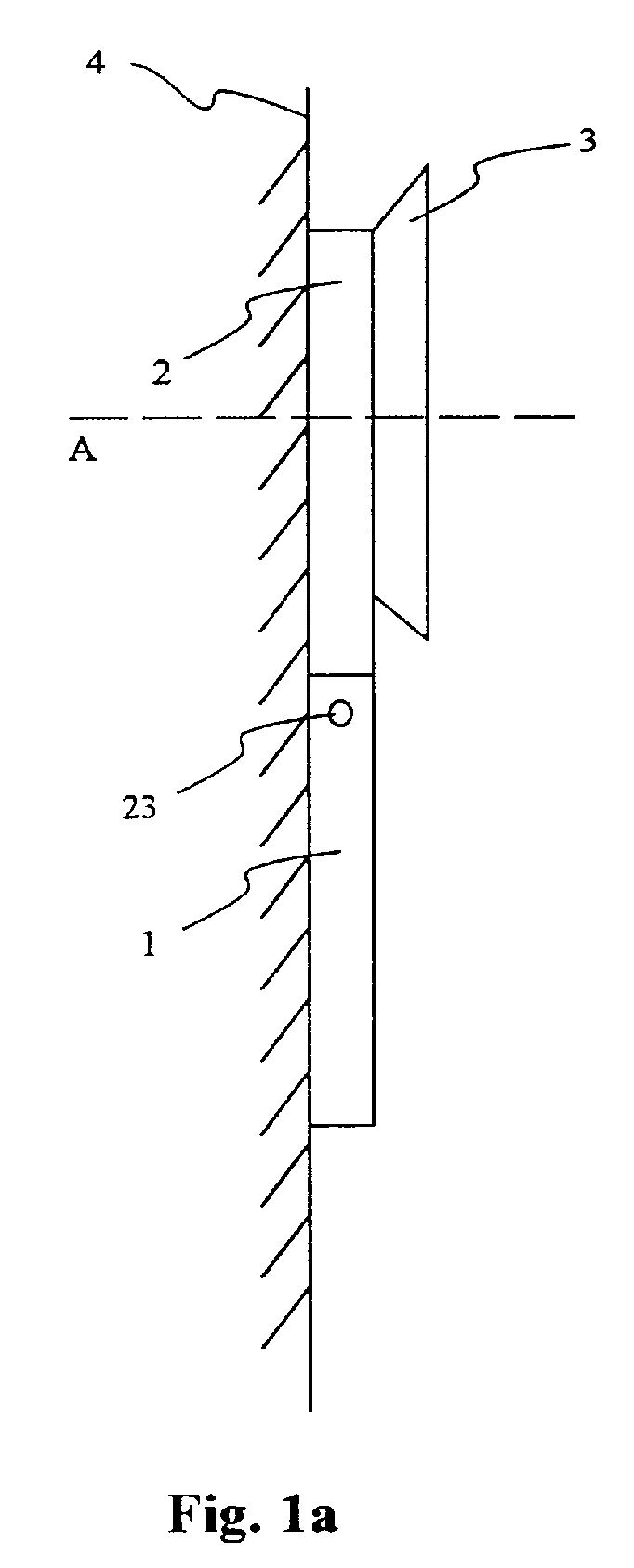
- Figure 1a shows a side view of the display apparatus according to the first embodiment of the invention fastened to a wall.
- the figure shows the support part 1 and the arm part 2 of the apparatus base as well as the display 3.
- the figure further shows a wall 4, to which the support part 1 of the base is fastened.
- the support part 1 of the apparatus base is arranged below the display 3, and the arm part 2 is fastened with any technique known per se, such as with a joint 23, at one end of the base part 1.
- the display 3 is twisted into the vertical or the horizontal position by twisting it in relation to an axis A passing perpendicularly through the display apparatus.
- the vertical and the horizontal positions of the display 3 are shown in more detail in figures 3a and 3b.
- Figure 1b shows a side view of the display apparatus according to the first embodiment of the invention fastened to a wall and inclined in relation to the wall.
- the display 3 is inclined, supported by the arm part 2 of the base, in the direction Z in relation to the wall 4, when the support part 1 of the base is fastened to the wall 4.
- the support part 1 and the arm part 2 of the base are arranged to be mutually connected with any means known per se, such as a hinge, over which the display 3 can be inclined in the Z direction.
- the figure further shows with a broken line an alternative structure of the support part of the base.
- the alternative structure 19 has the form of a thick U, whereby the arm part is fastened inside the arc of the U. Such a structure is particularly stable in a table top installation, as the branches of the U significantly enlarge the support area.
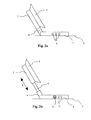
- Figure 2a shows further a side view of the display apparatus of the second embodiment of the invention mounted on a table top.
- the support part 1 of the base part is arranged on the table surface 5, whereby the arm part of the base can be arranged in relation the support part 1 in a desired inclination, like in the wall installation.
- the figure further shows how control means 6 for the display 3 are mounted in the base part of the apparatus.
- the display control means 6 comprise means for making the basic controls of the display, such as the contrast and brightness of the display 3 and the position and width of the picture in the display 3.
- the arm part of the base part is a two-part structure and comprises an upper part 7 to which the display is fastened, and a lower part 8, which is fastened to the support part 1 with a means known per se, such as a hinge.
- Figure 2b shows also in a side view the height adjustment of a display apparatus according to the second embodiment of the invention.
- the height of the apparatus can be adjusted in the Y direction with the aid of the arm part of the base.
- the height adjustment is made with the aid of a guide 9 between the upper part 7 and the lower part 8, the guide being any prior art solution known per se.
- the figure further shows schematically the audio equipment 10 and a number of controls 11 located in the base part of the apparatus.
- these means 10 located in the base part of the display as well as the controls 6, 11 are arranged in the base part of the apparatus which in a wall installation is located below the display, whereby they are easily manipulated.
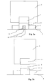
- Figure 3a shows in view from the back the display apparatus of the second embodiment of the invention where the display 3 is in a horizontal position
- figure 3b shows the display 3 in the vertical position.
- the position of the display is changed by twisting the display in relation to an imaginary axis, as is presented in figure la.
- a twisting of the display in this manner so that it is vertical or horizontal is known per se.
- Figure 3a shows in addition a way to arrange the cables according to a preferred embodiment of the invention.
- the lower part 8 of the arm part of the apparatus base part 1 there is arranged a space 13 for the cables 12, and in this space 12 the cables are protected when the apparatus is being placed in different positions.
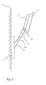
- Figure 4 shows the wall fasteners of the display apparatus of the third embodiment of the invention as seen from below the support part of the base.
- Preferably two wall installation fasteners 14 are arranged behind (as seen in relation to the display) of the support part 1 of the apparatus base, whereby the figure presents one embodiment with which the apparatus is fastened to screws etc. arranged in the wall.
- the wall installation fasteners 14 can be any prior art fasteners, and a required number of the fasteners can be used in order to provide a robust fastening.
- Figure 5 shows in a side view a display apparatus according to the fourth embodiment of the invention fastened to a wall.
- the apparatus comprises the support part 1 of the base part which is fastened to a wall 4, a display 3 which is fastened to the arm part 2 of the base part, and an extension arm of the base part which extension comprises an upper part 15, an extension part 16 and a lower part 17.
- the upper part 15 of the extension arm is fastened to the arm part 2 with any joint-like means known per se, for instance with a ball joint 18.
- the display 3 and the arm part 2 can be inclined in relation to the wall and the rest of the apparatus with the aid of the joint 18.
- the lower part 17 of the extension arm is also fastened to the support part 1 with a joint-like means known per se , such as a hinge.
- Figure 6a shows in a side view a display apparatus according to the fifth embodiment of the invention mounted on a table.
- the display apparatus comprises a base part 20 and a display 3 which is fastened to the base part 20 with fastening means known per se, such as a joint 21.
- Figure 6b shows the display apparatus of the fifth embodiment of the invention fastened to a wall.
- Figure 7a shows in a side view a display apparatus according to the sixth embodiment of the invention placed on a table.
- the display apparatus comprises a base part 1, a display 3 and an arm part 2.
- the arm part 2 is bent so that the display 3 fastened to it has a desired maximum inclination when the display apparatus is placed on a table.
- the arm part 2 is fastened to the base part 1 with a technique known per se, such as a joint 22.
- Figure 7b shows the display apparatus of the sixth embodiment of the invention fastened to a wall.
- FIG 8 shows in a front view a display apparatus according to the seventh embodiment of the invention.
- the display apparatus comprises a base part 23 and a display 3 which can be fastened to each other with a technique known per se, such as in any manner presented above.
- the display 3 comprises a camera 24 which is fastened to the display 3 with a technique known per se, which enables the camera 24 to be angled.
- the camera can be fastened to the display with a ball joint or with a telescopic arm, whereby the angling of the camera does not depend on the angle of the display.
- the camera can also be fixed to the display, because in multimedia equipment the most important task of the camera is generally to photograph the user, i.e. the person viewing the display, whereby this person can participate in a video conference.
- the base part according to the invention provides the user a possibility to place the display on a table top, on any wall or even on the ceiling or floor, whereby problems caused by the external lighting and/or by the room lighting can be avoided when the camera is used.
- the display 3 further comprises control means 6 for the display.
- the base part 23 of the display apparatus comprises an audio apparatus which comprises i.a. a microphone 10 and a number of controls 11.
Landscapes
- Physics & Mathematics (AREA)
- General Physics & Mathematics (AREA)
- Engineering & Computer Science (AREA)
- Theoretical Computer Science (AREA)
- Devices For Indicating Variable Information By Combining Individual Elements (AREA)
- Illuminated Signs And Luminous Advertising (AREA)
Abstract
- the display (3) and the base part can be moved in relation to each other, at least to a first operating position and to a second operating position, of which in the first operating position the direction of the support surface differs substantially 90 degrees from the direction of the support surface in the second operating position, and
- further the base part of the display apparatus comprises fastening means for fastening the display apparatus to a substantially planar surface.
Description
- the display and the base part can be moved in relation to each other, at least to a first operating position and to a second operating position, of which in the first operating position the direction of the support surface differs substantially 90 degrees from the direction of the support surface in the second operating position, and
- further the base part of the display apparatus comprises fastening means for fastening the display apparatus to a substantially planar surface.
Claims (18)
- Display apparatus comprising a display (3) and, connected to the display, a base part which forms a support surface for supporting the display apparatus on a substantially planar surface, characterised in thatthe display (3) and the base part can be moved in relation to each other, at least to a first operating position and to a second operating position, of which in the first operating position the direction of the support surface differs substantially 90 degrees from the direction of the support surface in the second operating position, andfurther the base part of the display apparatus comprises fastening means (14) for fastening the display apparatus to a substantially planar surface.
- A display apparatus according to claim 1, characterised in that the first operating position is a wall operating position, where the support surface is vertical and a considerable part of the base part is below the display (3).
- A display apparatus according to claim 1, characterised in that the second operating position is a table operating position where the support surface is horizontal and the centre of gravity of the display apparatus is on a vertical line passing through the support surface.
- A display apparatus according to claim 1, characterised in that the base part comprisesa support part (1) forming the support surface, andan arm part (2), which can be moved in relation to the support part (1).
- A display apparatus according to claim 4, characterised in that the arm part (2) comprises a basic part and an extension part (9), which can be moved in relation to the basic part.
- A display apparatus according to claim 4, characterised in that the arm part (2) of the base part is connected to the display (3) with a member comprising at least two parts, which parts of the member can be moved in relation to each other.
- A display apparatus according to claim 4, characterised in that the support part (1) and the arm part (2) of the base part are connected to each other with a member comprising at least two parts, which parts of the member can be moved in relation to each other.
- A display apparatus according to claim 1, characterised in that the base part comprises a support part (1), an arm part (2) and at least one additional arm.
- A display apparatus according to claim 8, characterised in that the additional arm comprises an extension part (16).
- A display apparatus according to claim 8, characterised in that the parts of the base part are connected to each other and/or to the display (3) with a member comprising at least two parts, which parts of the member are movable in relation to each other.
- A display apparatus according to claim 1, characterised in that the base part (20) comprises one part.
- A display apparatus according to claim 11, characterised in that the base part (20) is connected to the display (3) with a member comprising at least two parts, which parts of the member are movable in relation to each other.
- A display apparatus according to claim 1, characterised in that the display (3) can be arranged into a vertical position or a horizontal position by twisting it around a certain rotational axis.
- A display apparatus according to claim 1, characterised in that audio equipment and/or multimedia equipment (10) of the apparatus is arranged in the base part, the equipment comprising speakers, a microphone and/or a camera, and control means (11) for the equipment (10).
- A display apparatus according to claim 1, characterised in that a camera (24) is arranged in connection with the display (3), and that audio equipment is arranged in the base part, the equipment comprising a speaker, a microphone (10) and control means (11) for the equipment.
- A display apparatus according to claim 1, characterised in that control means (6) for the display are arranged in the base part.
- A display apparatus according to claim 1, characterised in that in the base part there is arranged a space (13) for the cables (12) of the apparatus.
- A method for changing the operating position of a display apparatus comprising a display (3) and a base part connected to the display, whereby the base part forms a support surface for supporting the display apparatus on a substantially planar surface, characterised in that it comprises steps, in whichthe display apparatus is detached from a first planar surface,the display (3) and the base part are moved substantially 90 degrees in relation to each other, andthe display apparatus is fastened to a second planar surface.
Applications Claiming Priority (2)
| Application Number | Priority Date | Filing Date | Title |
|---|---|---|---|
| FI991147 | 1999-05-20 | ||
| FI991147A FI991147A7 (en) | 1999-05-20 | 1999-05-20 | Display hardware |
Publications (2)
| Publication Number | Publication Date |
|---|---|
| EP1054373A2 true EP1054373A2 (en) | 2000-11-22 |
| EP1054373A3 EP1054373A3 (en) | 2001-01-10 |
Family
ID=8554698
Family Applications (1)
| Application Number | Title | Priority Date | Filing Date |
|---|---|---|---|
| EP00660089A Withdrawn EP1054373A3 (en) | 1999-05-20 | 2000-05-18 | Display apparatus |
Country Status (2)
| Country | Link |
|---|---|
| EP (1) | EP1054373A3 (en) |
| FI (1) | FI991147A7 (en) |
Cited By (2)
| Publication number | Priority date | Publication date | Assignee | Title |
|---|---|---|---|---|
| EP1401200A3 (en) * | 2002-09-19 | 2004-12-08 | Samsung Electronics Co., Ltd. | Display system |
| CN100394349C (en) * | 2002-05-28 | 2008-06-11 | 三星电子株式会社 | Display units and mounts |
Family Cites Families (4)
| Publication number | Priority date | Publication date | Assignee | Title |
|---|---|---|---|---|
| US4589659A (en) * | 1983-08-01 | 1986-05-20 | Nintendo Co., Ltd. | Foldable liquid crystal display unit |
| US4783036A (en) * | 1987-04-16 | 1988-11-08 | Anthro Corporation | Adjustable support |
| JPH09274444A (en) * | 1996-04-04 | 1997-10-21 | Hitachi Ltd | Liquid crystal display |
| DE29812218U1 (en) * | 1998-07-09 | 1999-01-07 | ANOVA Multimedia Studios GmbH, 18059 Rostock | Multimedia terminal |
-
1999
- 1999-05-20 FI FI991147A patent/FI991147A7/en unknown
-
2000
- 2000-05-18 EP EP00660089A patent/EP1054373A3/en not_active Withdrawn
Cited By (4)
| Publication number | Priority date | Publication date | Assignee | Title |
|---|---|---|---|---|
| CN100394349C (en) * | 2002-05-28 | 2008-06-11 | 三星电子株式会社 | Display units and mounts |
| EP1401200A3 (en) * | 2002-09-19 | 2004-12-08 | Samsung Electronics Co., Ltd. | Display system |
| US7097143B2 (en) | 2002-09-19 | 2006-08-29 | Samsung Electronics Co., Ltd. | Installation equipment for display main body and jig for installation equipment |
| CN100429604C (en) * | 2002-09-19 | 2008-10-29 | 三星电子株式会社 | Mounting equipment for display body and jig for mounting equipment |
Also Published As
| Publication number | Publication date |
|---|---|
| FI991147L (en) | 2000-11-21 |
| FI991147A0 (en) | 1999-05-20 |
| FI991147A7 (en) | 2000-11-21 |
| EP1054373A3 (en) | 2001-01-10 |
Similar Documents
| Publication | Publication Date | Title |
|---|---|---|
| US7530538B2 (en) | Flat screen television support system | |
| US8405704B2 (en) | TV conference apparatus | |
| US7738245B1 (en) | Display mount | |
| US7726617B2 (en) | Flat panel display mounting system | |
| US20040163574A1 (en) | Hospital bed table with a video display | |
| US6527237B2 (en) | Crossbar bracket assembly for speakers and monitors | |
| US6615551B2 (en) | Media wall | |
| US8827226B2 (en) | Single mount with dual method installation | |
| US7661643B2 (en) | Swivel mount system for a monitor | |
| CN1804715A (en) | Device and method for arranging a flat panel display | |
| US20060238661A1 (en) | Mounting system capable of adjusting viewing angle of a monitor | |
| EP1863424A2 (en) | Articulated boom for positioning video and medical equipment in hospital operating rooms | |
| CN104968986A (en) | dual display unit | |
| US7290888B2 (en) | Projection system | |
| EP1837585A3 (en) | Automatic wall mounting system for wall-mounted tv | |
| US9998706B2 (en) | Video conference endpoint displays | |
| US20070284492A1 (en) | Mounting bracket system capable of mounting a monitor between adjacent walls | |
| US9062817B1 (en) | Flat panel monitor ceiling mounting system | |
| CN101424367A (en) | Bracket and wall mount having the same | |
| KR102158818B1 (en) | Slim type wall mount | |
| US20050230590A1 (en) | Flat panel display ceiling mount | |
| KR101320968B1 (en) | Flat screen display device | |
| KR100538649B1 (en) | Computer LCD Monitor connecting Apparatus | |
| KR20210121431A (en) | Height-adjustable ladder bracket for wall-mounted TV | |
| CN217519568U (en) | Display device |
Legal Events
| Date | Code | Title | Description |
|---|---|---|---|
| PUAI | Public reference made under article 153(3) epc to a published international application that has entered the european phase |
Free format text: ORIGINAL CODE: 0009012 |
|
| AK | Designated contracting states |
Kind code of ref document: A2 Designated state(s): DE FR GB IT |
|
| AX | Request for extension of the european patent |
Free format text: AL;LT;LV;MK;RO;SI |
|
| PUAL | Search report despatched |
Free format text: ORIGINAL CODE: 0009013 |
|
| AK | Designated contracting states |
Kind code of ref document: A3 Designated state(s): AT BE CH CY DE DK ES FI FR GB GR IE IT LI LU MC NL PT SE |
|
| AX | Request for extension of the european patent |
Free format text: AL;LT;LV;MK;RO;SI |
|
| RIC1 | Information provided on ipc code assigned before grant |
Free format text: 7G 09F 9/00 A, 7G 09F 27/00 B |
|
| 17P | Request for examination filed |
Effective date: 20010515 |
|
| AKX | Designation fees paid |
Free format text: DE FR GB IT |
|
| RAP1 | Party data changed (applicant data changed or rights of an application transferred) |
Owner name: NOKIA CORPORATION |
|
| STAA | Information on the status of an ep patent application or granted ep patent |
Free format text: STATUS: THE APPLICATION IS DEEMED TO BE WITHDRAWN |
|
| 18D | Application deemed to be withdrawn |
Effective date: 20061201 |