EP1054224A2 - Condenser, power plant equipment and power plant operation method - Google Patents
Condenser, power plant equipment and power plant operation method Download PDFInfo
- Publication number
- EP1054224A2 EP1054224A2 EP00110544A EP00110544A EP1054224A2 EP 1054224 A2 EP1054224 A2 EP 1054224A2 EP 00110544 A EP00110544 A EP 00110544A EP 00110544 A EP00110544 A EP 00110544A EP 1054224 A2 EP1054224 A2 EP 1054224A2
- Authority
- EP
- European Patent Office
- Prior art keywords
- condensate
- steam
- condenser
- water
- water system
- Prior art date
- Legal status (The legal status is an assumption and is not a legal conclusion. Google has not performed a legal analysis and makes no representation as to the accuracy of the status listed.)
- Withdrawn
Links
- 238000000034 method Methods 0.000 title claims description 20
- XLYOFNOQVPJJNP-UHFFFAOYSA-N water Substances O XLYOFNOQVPJJNP-UHFFFAOYSA-N 0.000 claims abstract description 375
- 238000001514 detection method Methods 0.000 claims abstract description 128
- 239000013535 sea water Substances 0.000 claims abstract description 95
- 239000000126 substance Substances 0.000 claims abstract description 69
- 238000010790 dilution Methods 0.000 claims abstract description 32
- 239000012895 dilution Substances 0.000 claims abstract description 32
- 238000011144 upstream manufacturing Methods 0.000 claims description 36
- 238000007599 discharging Methods 0.000 claims description 10
- 230000003472 neutralizing effect Effects 0.000 claims description 5
- 239000003643 water by type Substances 0.000 claims 1
- 239000000498 cooling water Substances 0.000 description 21
- 238000010276 construction Methods 0.000 description 16
- 238000004891 communication Methods 0.000 description 12
- 238000012544 monitoring process Methods 0.000 description 12
- 238000010586 diagram Methods 0.000 description 9
- 238000011084 recovery Methods 0.000 description 9
- 230000000694 effects Effects 0.000 description 8
- 238000012986 modification Methods 0.000 description 8
- 230000004048 modification Effects 0.000 description 8
- 230000001105 regulatory effect Effects 0.000 description 7
- -1 for example Substances 0.000 description 6
- 230000001276 controlling effect Effects 0.000 description 5
- 239000007789 gas Substances 0.000 description 5
- 238000007689 inspection Methods 0.000 description 5
- 238000009835 boiling Methods 0.000 description 4
- 238000005192 partition Methods 0.000 description 4
- 238000012546 transfer Methods 0.000 description 4
- CURLTUGMZLYLDI-UHFFFAOYSA-N Carbon dioxide Chemical compound O=C=O CURLTUGMZLYLDI-UHFFFAOYSA-N 0.000 description 3
- 238000010793 Steam injection (oil industry) Methods 0.000 description 3
- 230000005574 cross-species transmission Effects 0.000 description 3
- 230000007423 decrease Effects 0.000 description 3
- 238000002347 injection Methods 0.000 description 3
- 239000007924 injection Substances 0.000 description 3
- 229910002092 carbon dioxide Inorganic materials 0.000 description 2
- 238000001816 cooling Methods 0.000 description 2
- 239000007788 liquid Substances 0.000 description 2
- 230000033228 biological regulation Effects 0.000 description 1
- 239000001569 carbon dioxide Substances 0.000 description 1
- 239000000567 combustion gas Substances 0.000 description 1
- 238000005260 corrosion Methods 0.000 description 1
- 230000007797 corrosion Effects 0.000 description 1
- 238000013016 damping Methods 0.000 description 1
- 230000003111 delayed effect Effects 0.000 description 1
- 238000003745 diagnosis Methods 0.000 description 1
- BNIILDVGGAEEIG-UHFFFAOYSA-L disodium hydrogen phosphate Chemical compound [Na+].[Na+].OP([O-])([O-])=O BNIILDVGGAEEIG-UHFFFAOYSA-L 0.000 description 1
- 239000003814 drug Substances 0.000 description 1
- 239000000446 fuel Substances 0.000 description 1
- 239000012535 impurity Substances 0.000 description 1
- 230000000116 mitigating effect Effects 0.000 description 1
- 230000001737 promoting effect Effects 0.000 description 1
- 230000003134 recirculating effect Effects 0.000 description 1
Images






Classifications
-
- F—MECHANICAL ENGINEERING; LIGHTING; HEATING; WEAPONS; BLASTING
- F28—HEAT EXCHANGE IN GENERAL
- F28F—DETAILS OF HEAT-EXCHANGE AND HEAT-TRANSFER APPARATUS, OF GENERAL APPLICATION
- F28F19/00—Preventing the formation of deposits or corrosion, e.g. by using filters or scrapers
-
- F—MECHANICAL ENGINEERING; LIGHTING; HEATING; WEAPONS; BLASTING
- F28—HEAT EXCHANGE IN GENERAL
- F28B—STEAM OR VAPOUR CONDENSERS
- F28B11/00—Controlling arrangements with features specially adapted for condensers
-
- F—MECHANICAL ENGINEERING; LIGHTING; HEATING; WEAPONS; BLASTING
- F28—HEAT EXCHANGE IN GENERAL
- F28F—DETAILS OF HEAT-EXCHANGE AND HEAT-TRANSFER APPARATUS, OF GENERAL APPLICATION
- F28F2265/00—Safety or protection arrangements; Arrangements for preventing malfunction
- F28F2265/16—Safety or protection arrangements; Arrangements for preventing malfunction for preventing leakage
Definitions
- the present invention relates to a condenser, a power plant and an operation method thereof.
- sea water is used as cooling water in the condenser as mentioned above, sea water has become a cause of corrosion or the like of structural apparatus and piping, etc. of the power plant when the sea water flowed into the condenser, so that it is necessary to monitor always water quality inside the system to find whether or not sea water leaks into the interior of the condenser. If the water quality inside the system exceeds a set value because of leakage of sea water into the interior of the condenser, a signal is issued from a detection part, and an alarm is generated on a monitor, operation panel, etc. An operator has received the alarm, identified a position and degree of the leakage, and judged whether or not the plant operation was stopped or continued according to the result, and they were operated manually.
- JP A 3-248030 JP A 6-11406 and JP A 5-264393.
- JP A 3-248030 discloses an apparatus in which a condenser hot well is divided into a first water chamber and a second water chamber by a partition wall, an electric conductivity measuring apparatus is provided in each water chamber and it is monitored whether or not an absolute value of difference between two electric conductivities is within an upper limit value.
- JP A 6-11406 discloses an apparatus in which the conductivity of a sample liquid which is taken from a condenser and deaerated by a gas-permeable film and the conductivity of a sample liquid taken from a recirculating water delivered by a condenser pump and deaerated in the similar manner are compared, whereby mixing of sea water is judged.
- JP A 5-264393 discloses an apparatus in which water quality is detected in a plurality of positions of piping of a condenser system, leakage is judged at each position and total diagnosis of those leakage conditions are classified in steps and displayed.
- JP A 3-248030, JP A 6-11406 and JP A 5-264393 each are provided with a detection point for taking out detection water in a condenser outlet through which the whole condensate passes, on the downstream side of a condenser pump for delivering condensate in the condenser, or in piping connecting from the condenser to a steam generator.
- the detection point is provided in the condenser outlet or on the downstream side of the condenser pump for delivering condensate in the condenser, or in the piping connecting the condenser to the steam generator, a time is taken until sea water leakage is detected, whereby there is the possibility that the water mixed with sea water is flowed out from the condenser even if the plant is stopped or a feed water system is closed after the detection of sea water leakage, and that the sea water-mixed water flows into the steam generator and steam turbine since the sea water-mixed water is delivered by the condenser pump.
- An object of the present invention is to provide a condenser, power plant equipment and operation method thereof, in which leakage of cooling water is detected early and it is suppressed that water mixed with sea water due to the sea water leakage or the like flows into a steam generator and a steam turbine.
- the present invention provides the following condenser:
- a condenser of the present invention condenses steam flowed therein from a turbine and supplies the condensate into a feed water system leading to a steam generator, and comprises a steam condensing zone having a heat exchanger tube bundle and condensing steam and a hot well zone allowing the condensate condensed in the steam condensing zone to stay, wherein
- a condenser condenses steam flowed therein from a turbine and supplies the condensate into a feed water system leading to a steam generator, and
- the detectors and/or detection ports are arranged separately from each other in a course leading from an upstream side of the hot well zone into which the condensate flows from the steam condensing zone to a downstream side of the hot well zone from which the condensate flows out into the feed water system, and a judging device for comparing respective water quality values detected from the detectors and/or detection ports, and judging sea water leakage when a water quality detection value detected from the detectors and/or detection ports on the upstream side represents to be lower in water quality detection value than a water quality detection value detected from the detectors and/or detection ports on the downstream side.
- the present invention provides the following power plant equipment:
- a power plant equipment comprises a steam generator generating steam, a steam turbine driven by the steam generated in the steam generator, a condenser condensing the steam exhausted from the steam turbine into condensate, and a feed water system supplying the condensate to the steam generator,
- a power plant equipment comprises a steam generator generating steam, a steam turbine driven by the steam generated in the steam generator, a condenser condensing the steam exhausted from the steam turbine into condensate, and a feed water system supplying the condensate to the steam generator,
- the above-mentioned power plant equipment is provided with a make-up water tank having make-up water stored therein and an apparatus for supplying the make-up water stored in the make-up water tank to the condenser or the feed water system.
- the above-mentioned power plant equipment is provided with a chemical storage tank storing chemical dilution water for neutralizing the condensate mixed with sea water, and a chemical dilution water supplying apparatus supplying the chemical dilution water stored in the chemical storage tank to the condenser or the feed water system.
- a discharging system for discharging, out of the feed water system, condensate on the upstream side of a control valve controlling a flow rate of the condensate to be supplied to the steam generator.
- the present invention provides the following operation method of power plant equipment:
- an operation method of a power plant equipment comprising a steam generator generating steam, a steam turbine driven by the steam generated in the steam generator, a condenser condensing the steam exhausted from the steam turbine into condensate, and a feed water system supplying the condensate to the steam generator, comprises the steps:
- a method of operating a power plant equipment which equipment comprises a steam generator generating steam, a steam turbine driven by the steam generated in the steam generator, a condenser condensing the steam exhausted from the steam turbine into condensate, and a feed water system supplying the condensate to the steam generator, comprises the steps:
- the condensate mixed with sea water is discharged out of the feed water system in a middle flow course from the condenser to the steam generator when judged to be sea water leakage.
- the method comprises:
- chemical may be medicine as long as it has a function of neutralizing sea water.
- Fig. 2 is a diagram of a system construction of a power plant of an embodiment of the present invention.
- a power plant of the present embodiment is roughly classified as and composed of a gas turbine system, a steam turbine system, a condenser, a feed water system and a steam generator system.
- the gas turbine system is composed of a compressor 1a compressing air, a combustor 1b mixing the air compressed by the compressor 1a with fuel and burning them, a gas turbine 1c driven by the combustion gas burnt by the combustor 1b.
- the steam turbine system is composed of a high pressure steam turbine 2, an intermediate pressure steam turbine 3 and a low pressure steam turbine 4. Steam heated by the steam generator system as described later is supplied to the steam turbine system. Further, in the present embodiment, the gas turbine 1, the high pressure steam turbine 2, the intermediate pressure steam turbine 3 and the low pressure steam turbine 4 have a driving shaft formed in one shaft, and electric power is generated by driving an electric generator 5 connected to the driving shaft.
- the condenser/feed water system is composed of a condenser 6 condensing into condensate the steam finished to work in the low pressure turbine 4 through heat-exchange with cooling water such as sea water, and feed water piping 6a supplying the condensate condensed by the condenser 6 to an exhaust heat recovery boiler system.
- the condensate condensed in the condenser 6 collects in a hot well zone not shown inside the condenser, and it is delivered from a lower portion of the condenser 6 to a condensate pump 13 to be raised in pressure.
- the condensate raised in pressure by the condensate pump 13 is supplied to each of a boiler feed water pump 15 and an exhausted heat recover boiler 16 through a condensate stop valve 23, a ground steam condenser 14 and a feed water stop valve 17. Further, in the case where water is in excess in the system, the excessive water is discharged out of the system through discharge piping 19 provided on the feed water piping 6a. by controlling a discharge flow regulation valve 20 provided thereon.
- auxiliary steam supply piping 27 auxiliarily supplying steam into the condenser 6 and promoting to deaerate and make-up water piping 22a are connected to the condenser 6.
- the make-up water piping 22a has a make-up water supply valve 21a mounted thereon and a make-up water tank 28 connected thereto through a make-up water pump 26 are connected.
- make-up water piping 22b supplying make-up water delivered by the make-up water pump 26 to the feed water piping 6a on the downstream side of a feed water stop valve 17 mounted the feed water piping 6a is connected to the make-up water piping 22a.
- This make-up water piping 22b has a make-up water supply valve 21b mounted thereon.
- make-up water to be supplied to the feed water piping 6a is introduced from the make-up water tank 28.
- a chemical storage tank 70 storing chemical or chemical dilution water is connected to the feed water piping 6a through a chemical supply piping 73.
- a chemical transfer pump 71 delivering chemical dilution water and a flow adjusting valve 72 adjusting a flow rate of the chemical dilution water are mounted on the chemical supply piping 73.
- an injection point of the chemical dilution water is arranged on the downstream side of the feed water stop valve 17, however, it is possible to inject it in the feed water piping 6a on the upstream side of the feed water stop valve 17, or into a boiler drum of the exhaust heat recovery boiler 16.
- the exhaust heat recovery boiler 16 which is the steam generator system
- steam is generated by using high temperature exhaust heat exhausted from the gas turbine.
- the condensate supplied by the boiler feed pump 15 is heated in the exhaust heat recovery boiler 16 to become steam, and the steam generated here flows through a main steam piping 9 and flows into the high pressure steam turbine 2.
- the steam exhausted from the high pressure steam turbine 2 flows through high pressure turbine exhaust piping 18, mixes with intermediate pressure steam and then is heated again by a reheater 18a of the exhaust heat recovery boiler 16.
- the steam reheated by the reheater 18a flows through reheat steam piping 7 and is supplied to the intermediate pressure steam turbine 3.
- the low pressure steam heated in the exhaust heat recovery boiler 16 is supplied to the intermediate pressure steam turbine 3 through low pressure steam piping 8.
- the steam supplied to the intermediate pressure steam turbine 3 through the reheat steam piping 7 and the low pressure steam piping 8 is mixed to be low pressure steam, and the low pressure steam is supplied to the low pressure turbine 4.
- high pressure turbine bypass piping 11, intermediate pressure turbine bypass piping 10 and low pressure turbine bypass piping 12 are connected to the reheat steam piping 7, the low pressure steam piping 8 and the main steam piping 9, respectively.
- the steam generated in the exhaust heat recovery boiler 16 is supplied to the condenser 6 through those bypass piping.
- Steam 35 exhausted from the steam turbine flows into the interior of a condenser barrel 31 from an upper portion of the condenser 6.
- the steam 35 flowed in the condenser barrel 31 passes through between a tube bundle 29 of heat conductive tubes in which cooling water, for example, sea water flows, whereby heat-exchange is effected.
- the steam 35 heat-exchanged is condensed to be condensate 44 and drops in a hot well zone 41.
- the dropped condensate 44 stays in the hot well zone 41, flows on a bottom surface inclined to a condenser outlet 36 and is led to the outside of the condenser 6.
- the condenser 6 of the present embodiment is provided with a plurality of detection water taking out ports 33, 39, 45 in the hot well zone 41 in which the condensate 44 drops.
- the detection water taking out ports 33 are arranged at positions right under the tube bundle 29, or at positions at which the condensate drops and stays first or in the vicinity thereof. That is, it is preferable to arrange them right under the tube bundle 29 at which steam heat-exchanges, or in the vicinity of the tube bundle 29.
- the detection water taking out port 39 is arranged at the condenser outlet 36 from which the condensate 44 stayed in the hot well zone 41 is discharged, or in the vicinity thereof.
- the detection water taking out port 45 is arranged at an about middle portion between the detection water taking out port 33 positioned right under the tube bundle 29 and the condenser outlet 36 from which the condensate 44 is discharged or its near portion, or at a position on the way of flow of the condensate 44 stayed in the hot well zone 41 to the condenser outlet 36.
- the detection water taken out at the detection water taking out ports 33, 39 and 45 are subjected to water quality inspection by an inspection apparatus not shown in Fig. 1. Further, in Fig. 1, the detection water taking out ports 45 also are arranged at corner portions of the hot well zone 41.
- water quality inspection of the condensate 44 is effected at the upstream and downstream positions in the hot well zone 41, at an about middle position of the flow path of condensate flowing from the upstream side to the downstream side in the hot well zone 41, or at a position on the way of the flow path. That is, the detection water taking out ports are separately arranged in the course inside the hot well zone 41 from the upstream side at which condensate condensed by the tube bundle 29 flows in to the downstream side at which the condensate is discharged. Further, detection water (condensate) taken out at the detection water taking out ports 33, 39, 45 shown in Fig. 1 is led to a water quality measuring apparatus not shown through piping connected to each of the detection water taking out ports, and the quality of the detection water taken out from each of the detection water taking out ports is inspected in the water quality measuring apparatus.
- the detection water is taken out from the detection water taking out ports as mentioned above, whereby the measuring conditions of the condensate are made closely constant and it possible to more surely and precisely detect sea water leakage. Details of sea water leakage detection method will be described later.
- the detection water taking out ports 33 are positioned right under the tube bundle 29, so that when sea water has leaked, sea water-mixed water is detected immediately after the condensate drops. Therefore, it is possible to take a long margin of time for taking countermeasures such as stop of condensate supply or the like by the time when the sea water-mixed condensate is supplied to the other plant components such as the steam generator, steam turbine, etc. Further, a detection value detected at the detection water taking out port 39 arranged in the vicinity of the condenser outlet 36 is delayed in time, as compared with a detection value detected right under the tube bundle 29.
- Fig. 1 an example is shown in which the detection water taking out ports 33, 39, 45 are arranged in the hot well zone 41 as means for detecting the water quality of condensate, however, it is also possible to provide detectors which can detect sea water leakage. In this case, it is desirable to arrange the detectors at the same position as or in the vicinity of the detection water taking out ports 33, 39, 45 shown in Fig. 1. Further, it is also possible to arrange a combination of the detection water taking out ports and the detectors.
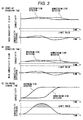
- Fig. 3 shows an example of characteristics of electric conductivity and conductivity difference.
- A, B and C in Fig. 3 show electric conductivity characteristics at time of plant start-up, in time of usual operation and at time of sea water leakage, respectively.
- conductivity detectors are used for water quality inspection, and the detection water taking out ports are arranged at the position right under the tube bundle 29, which is an upstream side in the hot well zone, and at the position of the condenser outlet 36 which is a downstream side.
- the conductivity of the whole system changes largely at time of start by an influence of dissolved carbon dioxide, impurities, etc. That is, as shown in A, the conductivity becomes high at time of start or the like because a lot of dissolved carbon dioxides are contained, while the conductivity becomes low during usual operation as shown in B. Therefore, it can not be determined by monitoring only absolute values of the conductivity whether a cause of increase in the conductivity is due to the start or the like or due to leakage of cooling water such as sea water, so that it was necessary to switch a limit value for issuing alarm according to the operation conditions.
- the detection water taking out ports are arranged at positions on the upstream side and downstream side in the hot well zone, and difference in conductivity between detectors at the two positions is monitored.
- sea water-mixed water is detected by the detector at the upstream side, and then detected by the detector at the downstream side with delay in time. Therefore, indication values of the detectors are largely different until the sea water-mixed water reaches the detector at the downstream side, and the difference in conductivity is large. Therefore, monitoring difference in conductivity between two positions makes it possible to early detect the leakage of sea water, and it is possible to detect only the leakage of cooling water such as sea water with high precision without resetting the limit value of alarm depending on the operation conditions.
- the leakage is on a large scale or on a small scale, based on a degree of change in conductivity difference between at the two detection points. That is, the case where the conductivity difference increases rapidly to time passage or the case where the conductivity difference exceed a limit value set in advance each are judged that leakage on a large scale occurred. Further, the case where the conductivity difference slowly increases or the case where the conductivity difference is smaller than the limit value set in advance but the detected conductivity value does not decrease even after a certain time period has passed is judged that the leakage is on a small scale.
- the plant operation is stopped or the load is reduced to a load at which the operation is judged to be safe, and the system is separated so that the condensate mixed with cooling water such as sea water does not flow in.
- cooling water such as sea water
- Fig. 4 is a flow chart showing details of the plant operation method at the time of sea water leakage.
- step 101 water quality inspection or monitoring inside the condenser is effected at upstream and downstream sides in the hot well zone (step 101).
- Judgement is effected on whether or not a detection value detected at the detecting point on the upstream side or on the downstream side is higher than a value set in advance (step 102), when values detected at the points on the upstream and downstream sides are lower than the set value, it is judged to be no leakage of sea water (step 103).
- a detection value detected by at least one of the detectors arranged on the upstream side inside the condenser indicates a higher value than the preset value, it is compared with a detection value detected at the detecting point on the downstream side (step 104).
- step 105 when a difference from the detection value at the detecting point on the downstream side is larger than a value set in advance, it is judged that leakage of sea water on a large scale occurred inside the condenser (step 105).
- a signal of sea water leakage is received and countermeasures for the inflow of sea water-mixed water into the steam generator or the like is automatically taken (step 106).
- a feed water stop valve 17 arranged on the upstream side of the steam generator is closed, whereby the sea water-mixed water flowing from the condenser is prevented from flowing to the downstream side.
- make-up water stored in the make-up water tank is supplied to the feed water piping by the make-up water pump.
- a discharge flow adjusting valve arranged on an discharge piping of a spill-over system is controlled to open by a controller, whereby excessive water is discharged (step 107).
- a condensate stop valve arranged on the upstream side of the steam generator is closed, whereby the sea water-mixed water flowing from the condenser is suppressed to flow to a downstream side.
- make-up water stored in the make-up water tank is supplied to the feed water piping by the make-up water pump.
- the discharge flow adjusting valve arranged on the discharge piping of the spill-over system is controlled to open by the controller, whereby excessive water is discharged (step 108).
- a measure for reducing or mitigating an influence of the inflow of sea water-mixed water into the steam generator or the like is taken (step 112).
- the reducing measure for example, chemical or chemical dilution water for neutralizing the sea water-mixed water is injected, whereby an emergency measure is taken (step 113).
- the water quality monitor on whether or not it is necessary to stop the plant or take a load down operation is continued (step 114).
- step 109 when it was judged to be insufficient only by injection of chemical or chemical dilution water, the plant load down operation or plant stop operation is conducted (step 109), and when it was judged to be unnecessary to take the plant stop or the load down operation, the plant operation is continued (step 116).
- chemical or chemical dilution water soda phosphate or the like is generally used.
- a difference between the value and a value of the detector arranged on the downstream side is smaller than a value set in advance and a detected value of conductivity decreases as operation time passes, such a case is judged to be a temporary rise in conductivity as at time of start (step 115) and the plant operation is continued (step 116).
- FIG. 5 is a schematic diagram of a system construction formed by simplifying the system construction in Fig. 2, and explanation of the same parts as in Fig. 2 are omitted.
- the condenser 6 has a hot well zone not shown which is provided with an inlet and an outlet, at each of which detection water taking out ports are provided as previously described.
- the water taken out through piping is monitored of its quality at detecting portions 65, 55.
- the condenser 6 is provided with a water level meter 66, a water level of the condensate stayed in the hot well zone is detected.
- Information detected at the detecting portions 65, 55 and by the water level meter 66 is transmitted to a controller 64.
- the controller 64 controls opening/closing of the feed water stop valve 17, the make-up water supply valve 21b and the discharge flow regulating valve 20 on the basis of the transmitted information.
- detection of condensate is carried out at the detecting portions 65, 55 and the controller 64 detects change in detection values to judge a degree of leakage. If leakage of sea water occurred inside the condenser 6, it is necessary to suppress the inflow of sea water-mixed water into plant elements such as the steam turbine and so on and promptly separate the leakage portion. If a degree of the leakage is judged to be on a large scale by a detection result, the feed water stop valve 17 arranged on the upstream of the steam generator 60 is closed, thereby to prevent the sea water-mixed water flowed out of the condenser from flowing downstream.
- make-up water stored in the make-up water tank is supplied to the feed water piping 6a by the make-up water pump 26.
- the discharge flow regulating valve 20 arranged on the discharge piping of the spill-over system is controlled so as to open by the controller 64, whereby excessive water is discharged.
- the controller 64 stops the feed water stop valve 17, makes up water to a downstream side of the feed water stop valve 17 and discharges, out of the system, the water which became excess by supply of the make-up water, whereby it is possible without depending on judgment of an operator to suppress, early and with high reliability, the outflow of cooling water-mixed condensate to a downstream side and the inflow thereof into the steam turbine 51 through the steam generator 60. Further, according to the present embodiment, it is possible to effect load down to a safety load at which an effect of leakage is not affected to the plant components, without emergency stop of the plant.
- Fig. 6 is a schematic diagram of another system construction formed by simplifying the system construction shown in Fig. 2, and explanation of the same parts as in Fig. 2 are omitted.
- a chemical storage tank 70 in which chemical or chemical dilution water is stored, a chemical supply piping 73 leading chemical or chemical dilution water to the steam generator 60, a chemical transfer pump 71 arranged on the chemical supply piping 73 and transferring chemical or chemical dilution water, and a flow regulating valve 72 regulating a flow rate of chemical or chemical dilution water to be supplied to the steam generator 60.
- the detection water taking out ports are provided as previously described, and the water taken out through piping is monitored of its quality at the detecting portions 65, 55.
- Information detected at the detecting portions 65, 55 is transmitted to the controller 64.
- the controller 64 controls the chemical transfer pump 71 and flow regulating valve 72 on the basis of the transmitted information.
- the quality monitoring of condensate is carried out at the detecting portions 65, 55 and the controller 64 detects a change in detection values to judge a degree of leakage. If the leakage of cooling water, for example, sea water occurred inside the condenser 6 and a degree of the leakage is judged to be on a small scale, chemical or chemical dilution water in the chemical storage tank 70 is supplied into the feed water piping 6a by the chemical transfer pump 71 while continuing the operation of the plant, and then the plant is stopped manually.
- cooling water for example, sea water occurred inside the condenser 6 and a degree of the leakage is judged to be on a small scale
- Fig. 7 is a view of a modification of the condenser shown in Fig. 1.
- the inside of the condenser is partitioned into a steam condensing zone 40 and a hot well zone 41 by a structural member 30 such as a top plate.
- Steam 35 exhausted from the steam turbine flows from upward of the condenser 6 into the steam condensing zone 40 inside a condenser barrel 31.
- the steam 35 flowed in passes through the tube bundle 29 inside which cooling water such as sea water flows, whereby heat exchange is effected.
- the heat-exchanged steam 35 is condensed to be condensate and the condensate drops onto the structural member 30.
- the condensate dropped on the structural member 30 flows on the structure member 30 and flows into the hot well zone 41 through a communication portion 34 formed at a corner of the structural member 30.
- the condensate introduced into the hot well zone 41 flows inside the hot well zone 41 and is discharged to the outside at the condenser outlet 36.
- the communication portion 34 communicating the steam condensing zone 40 and the hot well zone 41 is formed so that the condensate flows therein at a farthest portion from the condenser outlet 36 with respect to a water flow inside the hot well zone 41.
- the detection water taking out port 33 for monitoring the quality of condensate is arranged right under the communication portion 34 or in the vicinity thereof, that is, at the most upstream side in the hot well zone 41. Further, the detection water taking out port 39 is arranged at the condenser outlet 36 for discharging the condensate 44 stayed in the hot well zone 41 or in the vicinity thereof, that is, at the most downstream portion in the hot well zone 41.
- the detection water taking out port 45 is arranged around a middle portion between the detection water taking out port 33 arranged at the portion at which the condensate 44 flows in the hot well zone 41 or in the vicinity thereof and the detection water taking out port 39 arranged at the condenser outlet 36 discharging the condensate 44 stayed in the hot well zone 41 or in the vicinity thereof, or it is arranged at a portion on the way of a flow path in which the condensate 44 flowed in the hot well zone 41 flows to the condenser outlet 36.
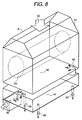
- Fig. 8 is a view of another modification of the condenser shown in Fig. 1.
- the steam condensing zone 40 and hot well zone 41 are constructed in independent boxes, respectively.
- Steam 35 exhausted from the steam turbine flows from an upper portion of the condenser 6 into the steam condensing zone 40 inside a condenser barrel 31.
- the steam 35 flowed in passes through the tube bundle 29 inside which cooling water such as sea water flows, whereby heat exchange is effected.
- the heat-exchanged steam 35 is condensed to be condensate and the condensate drops onto a bottom of the steam condensing zone 40 of the box.
- the condensate dropped on the bottom of the steam condensing zone 40 is introduced into the hot well zone 41 through a communication portion 42 formed at a corner of the steam condensing zone 40.
- the condensate introduced into the hot well zone 41 is discharged to the outside at the condenser outlet 36.
- the communication portion 42 communicating the steam condensing zone 40 and the hot well zone 41 is formed so that the condensate flows therein at a farthest portion from the condenser outlet 36 with respect to a water flow inside the hot well zone
- the detection water taking out port 33 for monitoring the quality of condensate is arranged right under the communication portion 42 or in the vicinity thereof, that is, at the most upstream side in the hot well zone 41. Further, the detection water taking out port 39 is arranged at the condenser outlet 36 for discharging the condensate 44 stayed in the hot well zone 41 or in the vicinity thereof, that is, at the most downstream portion in the hot well zone 41.
- the detection water taking out port 45 is arranged around a middle portion between the detection water taking out port 33 arranged at the portion at which the condensate 44 flows in the hot well zone 41 or in the vicinity thereof and the detection water taking out port 39 arranged at the condenser outlet 36 discharging the condensate 44 stayed in the hot well zone 41 or in the vicinity thereof, or it is arranged at a portion on the way of a flow path in which the condensate 44 flowed in the hot well zone 41 flows to the condenser outlet 36.
- the detection water taking out port 33 even if leakage of cooling water, for example, sea water occurred, it is possible to detect the leakage by the detection water taking out port 33 immediately after sea water-mixed water flows into the hot well zone 41. Further, by arranging the detection water taking out port 33 at the most upstream side in the hot well zone 41, therefore, it is possible to make long a margin in time necessary to take measures for stopping supply of condensate and so on by the time that the condensate mixed with sea water is supplied to the other plant components such as the steam generator, steam turbine and so on.
- the detecting portions are provided at a plurality of positions of the most upstream and downstream portions in the hot well zone 41 and intermediate portions therebetween, and it is possible to surely judge whether the leakage is on a large scale or on a small scale by examining a degree of change in conductivity difference therebetween. Accordingly, by monitoring a difference in conductivity between at two detecting points, early detection of leakage becomes possible, further it is possible to surely judge whether the leakage of sea water is on a large scale or on a small scale without resetting a limit value for alarm according to operational conditions. Further, in the case where it is judged to be leakage of sea water, countermeasures therefor is selected according to the scale of the sea water leakage in the same manner as in the flow chart of Fig. 4 as previously mentioned.
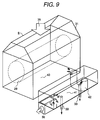
- Fig. 9 is a view of another modification of the condenser shown in Fig. 1.
- the steam condensing zone 40 and hot well zone 41 are constructed in independent boxes, respectively and arranged in an adjacent relation.
- the steam 35 flowed in the condenser 6 is condensed to be condensate and the condensate drops onto a bottom of the steam condensing zone 40 of the box.
- the condensate dropped on the bottom of the steam condensing zone 40 is introduced into the hot well zone 41 through a communication portion 42 formed at a corner of the steam condensing zone 40.
- the condensate introduced into the hot well zone 41 is discharged to the outside at the condenser outlet 36.
- an outlet of the communication portion 42 communicating from the steam condensing zone 40 to the hot well zone 41 is formed so that the condensate flows therein at a farthest portion from the condenser outlet 36 with respect to a water flow inside the hot well zone 41.
- the detection water taking out port 33 for monitoring the quality of condensate is arranged right under the communication portion 42 or in the vicinity thereof, that is, at the most upstream side in the hot well zone 41. Further, the detection water taking out port 39 is arranged at the condenser outlet 36 for discharging the condensate 44 stayed in the hot well zone 41 or in the vicinity thereof, that is, at the most downstream portion in the hot well zone 41.
- a detection water taking out port 45 can be arranged around a middle portion between the detection water taking out port 33 and the detection water taking out port 39, or at a portion on the way of a flow path in which the condensate 44 flowed in the hot well zone 41 flows to the condenser outlet 36.
- the detection water taking out port 33 even if leakage of cooling water, for example, sea water occurs, it is possible to detect the leakage by the detection water taking out port 33 immediately after sea water-mixed water flows into the hot well zone 41. Further, by arranging the detection water taking out port 33 at the most upstream side in the hot well zone 41, it is possible to make long a margin in time necessary to take measures for stopping supply of condensate and so on by the time that the condensate mixed with sea water is supplied to the other plant components such as the steam generator, steam turbine and so on.
- the detecting portions are provided at a plurality of positions of the most upstream and downstream portions in the hot well zone 41 and intermediate portions therebetween, and it is possible to surely judge whether the leakage is on a large scale or on a small scale by examining a degree of change in conductivity difference therebetween. Accordingly, by monitoring a difference in conductivity between at two detecting points, early detection of the leakage becomes possible, further it is possible to surely judge whether the leakage of sea water is on a large scale or on a small scale without resetting a limit value for alarm according to operational conditions. Further, in the case where it is judged to be leakage of sea water, countermeasures therefor is selected according to the scale of the sea water leakage in the same manner as in the flow chart of Fig. 4 as previously mentioned.
- Fig. 10 is a view of another modification of the condenser shown in Fig. 1.
- a condenser 6 is partitioned into a steam condensing zone 40 and a hot well zone 41 by a top plate 43, and the interior of the hot well 41 is partitioned by a partition plate 37 to form a narrow path.
- a deareating steam injection pipe 32 for injecting steam onto condensate in the hot well zone 41 is provided inside the condenser 6. Steam to be injected is led to the interior of the condenser through a deareating steam pipe 38 connected to the deareating steam injection pipe 32.
- Steam 35 exhausted from the steam turbine flows from upward of the condenser 6 into the steam condensing zone 40 inside a condenser barrel 31.
- the steam 35 flowed in there passes through the tube bundle 29 inside which cooling water such as sea water flows, whereby heat exchange is effected.
- the heat-exchanged steam 35 is condensed to be condensate and the condensate drops onto the top plate 43.
- the condensate dropped on the top plate 43 flows on the top plate 43 and is introduced into the hot well zone 41 through a communication portion 34 formed at a corner of the top plate 43.
- the condensate introduced into the hot well zone 41 flows along the narrow path formed by the partition plate 37 and is discharged to the outside at the condenser outlet 36.
- the communication portion 34 communicating the steam condensing zone 40 and the hot well zone 41 is formed so that the condensate flows therein at a farthest portion from the condenser outlet 36 with respect to a water flow inside the hot well zone 41.
- the detection water taking out port 33 for monitoring the quality of condensate is arranged right under the communication portion 34 or in the vicinity thereof, that is, at the most upstream side in the hot well zone 41. Further, the detection water taking out port 39 is arranged at the condenser outlet 36 for discharging the condensate 44 stayed in the hot well zone 41 or in the vicinity thereof, that is, at the most downstream portion in the hot well zone 41.
- a detection water taking out port 45 can be arranged around a middle portion between the detection water taking out port 33 and the detection water taking out port 39, or at a portion on the way of a flow path in which the condensate 44 flowed in the hot well zone 41 flows to the condenser outlet 36.
- the hot well zone 41 since an upper portion of the hot well zone 41 is covered widely with the top plate 43 and the hot well zone 41 is partitioned by the partition plate 37 to form the narrow path thereby to cause the condensate to flow along the narrow path, even if leakage of sea water occurs, it is possible to make long a margin in time necessary to take measures for stopping supply of condensate and so on by the time that the condensate mixed with sea water goes into the system from the condenser hot well zone, that is, the condensate mixed with sea water is supplied to the other plant components such as the steam generator, steam turbine and so on.
- the detection water taking out port 33 is arranged at the most upstream portion in the hot well zone 41, it is possible to detect the leakage of sea water-mixed water immediately after the sea water-mixed water flows in the hot well 41.
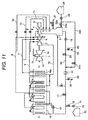
- Fig. 11 is a system construction view of an electric power plant of another embodiment of the present invention. Explanation of the same constructions as in Fig. 2 is omitted here.
- the make-up water piping 22b leading make-up water is connected on the downstream side of the feed water stop valve 23, that is, on the upstream side of the ground steam condenser 14. Further, a discharge pipe 25 with a discharge flow adjusting valve 24 is arranged on the downstream side of the condenser pump 13.
- Fig. 12 is a view of a system construction simplified of one shown in Fig. 11.
- detection water taking out ports are provided as previously described, and the water taken out through piping is monitored of its quality at detecting portions 65, 55. Further, the condenser 6 is provided with a water level meter 66, a water level of the condensate stayed in the hot well zone is detected. Information detected at the detecting portions 65, 55 and by the water level meter 66 is transmitted to a controller 64.
- the controller 64 controls opening/closing of a condensate stop valve 23, make-up water supply valve 21b and discharge flow regulating valve 20 on the basis of the transmitted information.
- detection of condensate is carried out at the detecting portions 65, 55 and the controller 64 detects a change in detection value to judge a degree of leakage. If leakage of cooling water, for example, sea water occurred inside the condenser 6, it is necessary to suppress inflow of sea water-mixed water into plant elements such as the steam turbine and so on and promptly separate the leakage portion. If the degree of leakage is judged to be on a large scale from a detection result, the condensate stop valve 23 arranged on the downstream of the condenser valve 13 is closed, thereby to prevent the sea water-mixed water flowed out of the condenser from flowing downstream.
- make-up water stored in the make-up water tank 28 is supplied to the feed water piping 6a by the make-up water pump 26.
- the discharge flow regulating valve 24 arranged on the discharge piping 25 is controlled so as to open by the controller 64, whereby excessive water is discharged.
- the controller 64 stops the condensate stop valve 23, makes up the make-up water to a downstream side of the condensate stop valve 23 and discharges, out of the system from a downstream side of the condensate pump 13, the water which became excess by supply of make-up water, whereby it is possible to suppress early and with high reliability the outflow of cooling water-mixed condensate to a downstream side of the condenser and the inflow thereof into the steam turbine 51 or the like through the steam generator 60, without depending on judgment of an operator. Further, according to the present embodiment, it is possible to effect load down to a safety load at which an effect of leakage is not affected to the plant components, without emergency stop of the plant.
Landscapes
- Engineering & Computer Science (AREA)
- Mechanical Engineering (AREA)
- General Engineering & Computer Science (AREA)
- Physics & Mathematics (AREA)
- Thermal Sciences (AREA)
- Monitoring And Testing Of Nuclear Reactors (AREA)
- Heat Treatment Of Water, Waste Water Or Sewage (AREA)
Abstract
Description
Claims (20)
- A condenser condensing steam flowed therein from a turbine and supplying the condensed condensate into a feed water system leading to a steam generator,wherein said condenser comprises a steam condensing zone having a heat exchanger tube bundle and condensing steam and a hot well zone allowing the condensate condensed in said steam condensing zone to stay there,a plurality of detectors for detecting the quality of the condensate and/or detection ports for taking out the condensate are provided in said hot well zone, anda control valve adjusting supply of the condensate to be supplied from said condenser to said feed water system on the basis of water quality detection values detected by said plurality of detectors and/or detection ports is provided on said feed water system, and a make-up water system supplying make-up water to said feed water system on the downstream side of said control valve is provided.
- A condenser condensing steam flowed therein from a turbine and supplying the condensed condensate into a feed water system leading to a steam generator,wherein said condenser comprises a steam condensing zone having a heat exchanger tube bundle and condensing steam and a hot well zone allowing the condensate condensed in said steam condensing zone to stay,a plurality of detectors for detecting the quality of the condensate and/or detection ports for taking out the condensate are provided in said hot well zone, anda chemical injecting system supplying chemical dilution water to said feed water system on the basis of water quality detection values detected by said plurality of detectors and/or detection ports is provided.
- A condenser according to claim 1 or 2, wherein said detectors and/detection ports are arranged separately from each other in a course leading from an upstream side of said hot well zone into which the condensate flows from said steam condensing zone to a downstream side of said hot well zone from which the condensate flows out into said feed water system, and a judging device for comparing respective water quality values detected by said detectors and/or detection ports, and judging sea water leakage when a water quality detection value detected by said detectors and/or detection ports on the upstream side represents to be lower in water quality than a water quality detection value detected by said detectors and/or detection ports on the downstream side.
- A condenser condensing steam flowed therein from a turbine and supplying the condensed condensate into a feed water system leading to a steam generator,wherein said condenser comprises a steam condensing zone having a heat exchanger tube bundle and condensing steam, a hot well zone allowing the condensate condensed in said steam condensing zone to stay and a condensate outlet portion leading the condensate stayed in said hot well zone from said condenser to said feed water system,a first detecting means for detecting the quality of the condensate is provided in said hot well zone right under the heat exchanger tube bundle forming said steam condensing zone and a second detecting means for detecting the quality of the condensate is provided at said condensate outlet portion or in the vicinity of said condensate outlet portion,a control valve adjusting supply of the condensate to be supplied from said condenser to said feed water system on the basis of a difference between water quality detection values of the condensate detected by said first and second detecting means is provided on said feed water system, anda make-up water system supplying make-up water to said feed water system on the downstream side of said control valve is provided.
- A condenser condensing steam flowed therein from a turbine and supplying the condensed condensate into a feed water system leading to a steam generator,wherein said condenser comprises a steam condensing zone having a heat exchanger tube bundle and condensing steam, a hot well zone allowing the condensate condensed in said steam condensing zone to stay and a condensate outlet portion leading the condensate stayed in said hot well zone from said condenser to said feed water system,a first detecting means for detecting the quality of the condensate is provided in said hot well zone right under the heat exchanger tube bundle forming said steam condensing zone and a second detecting means for detecting the quality of the condensate is provided at said condensate outlet portion or in the vicinity of said condensate outlet portion, anda chemical injecting system supplying chemical dilution water into said feed water system on the basis of a difference between water quality detection values detected by said first and second detecting means is provided.
- A condenser condensing steam flowed therein from a turbine and supplying the condensed condensate into a feed water system leading to a steam generator,wherein said condenser comprises a steam condensing zone having a heat exchanger tube bundle and condensing steam, a hot well zone partitioned from said steam condensing zone, a condensate communicating portion introducing the condensate condensed in said steam condensing zone to said hot well zone and a condensate outlet portion leading the condensate stayed in said hot well zone from said condenser to said feed water system,a first detecting means for detecting the quality of condensate is provided in said condensate communicating portion introducing the condensed condensate from said steam condensing zone to said hot well zone or in the vicinity of said condensate communicating portion and a second detecting means for detecting the quality of condensate is provided at said condensate outlet portion leading the condensate stayed in said steam condensing zone from said condenser to said feed water system or in the vicinity of said condensate outlet portion,a control valve adjusting supply of the condensate to be supplied from said condenser to said feed water system on the basis of a difference between water quality detection values of the condensate detected by said first and second detecting means is provided on said feed water system, anda make-up water system supplying make-up water to said feed water system on the downstream side of said control valve is provided.
- A condenser condensing steam flowed therein from a turbine and supplying the condensed condensate into a feed water system leading to a steam generator,wherein said condenser comprises a steam condensing zone having a heat exchanger tube bundle and condensing steam, a hot well zone partitioned from said steam condensing zone, a condensate communicating portion introducing the condensate condensed in said steam condensing zone to said hot well zone and a condensate outlet portion leading the condensate stayed in said hot well from said condenser to said feed water system,a first detecting means for detecting the quality of condensate is provided in said condensate communicating portion introducing the condensed condensate from said steam condensing zone to said hot well zone or in the vicinity of said condensate communicating portion and a second detecting means for detecting the quality of condensate is provided at said condensate outlet portion leading the condensate stayed in said steam condensing zone from said condenser to said feed water system or in the vicinity of said condensate outlet portion, anda chemical injecting system supplying chemical dilution water into said feed water system on the basis of a difference between water quality detection values detected by said first and second detecting means is provided.
- A condenser condensing steam flowed therein from a turbine and supplying the condensed condensate into a feed water system leading to a steam generator,wherein said condenser comprises a steam condensing chamber having a heat exchanger tube bundle and condensing steam, a hot well chamber partitioned from said steam condensing chamber, a condensate communicating portion introducing the condensate condensed in said steam condensing chamber to said hot well chamber and a condensate outlet portion leading the condensate stayed in said hot well chamber from said condenser to said feed water system,a first detecting means for detecting the quality of condensate is provided in said condensate communicating portion introducing the condensed condensate from said steam condensing chamber to said hot well chamber or in the vicinity of said condensate communicating portion and a second detecting means for detecting the quality of condensate is provided at said condensate outlet portion leading the condensate stayed in said steam condensing chamber from said condenser to said feed water system or in the vicinity of said condensate outlet portion,a control valve adjusting supply of the condensate to be supplied from said condenser to said feed water system on the basis of a difference between water quality detection values of the condensate detected by said first and second detecting means is provided on said feed water system, anda make-up water system supplying make-up water to said feed water system on the downstream side of said control valve is provided.
- A condenser condensing steam flowed therein from a turbine and supplying the condensed condensate into a feed water system leading to a steam generator,wherein said condenser comprises a steam condensing zone having a heat exchanger tube bundle and condensing steam, a hot well zone partitioned from said steam condensing zone, a condensate communicating zone introducing the condensate condensed in said steam condensing zone to said hot well zone and a condensate outlet portion leading the condensate stayed in said hot well zone from said condenser to said feed water system,a first detecting means for detecting the quality of condensate is provided in said condensate communicating portion introducing the condensed condensate from said steam condensing zone to said hot well zone or in the vicinity of said condensate communicating portion and a second detecting means for detecting the quality of condensate is provided at said condensate outlet portion leading the condensate stayed in said steam condensing zone from said condenser to said feed water system or in the vicinity of said condensate outlet portion, anda chemical injecting system supplying chemical dilution water into said feed water system on the basis of a difference between water quality detection values detected by said first and second detecting means is provided.
- A condenser according to claim 4, 5, 6, 7 , 8 or 9, wherein said condenser is provided with a judging device for comparing a difference between respective water quality values of the condensate detected by said first and second detecting means, and judging sea water leakage when a water quality detection value detected by said first detecting means represents to be lower in water quality than a water quality detection value detected by said second detecting means.
- A power plant equipment comprising a steam generator generating steam, a steam turbine driven by the steam generated in said steam generator and a condenser according to one of the claims 1, 2 or 4.
- A power plant equipment comprising a steam generator generating steam, a steam turbine driven by the steam generated in said steam generator and a condenser according to claim 5, wherein the chemical dilution water is supplied when the water quality of the condensate is lowered.
- A power plant equipment according to claim 11, wherein said power plant equipment comprises a make-up water tank having make-up water stored therein, a make-up water supply device for supplying the make-up water stored in said make-up water tank to said condenser or said feed water system.
- A power plant equipment according to claim 11 or 12, wherein said power plant equipment comprises a chemical storage tank storing chemical dilution water for neutralizing the condensate mixed with sea water, and a chemical dilution water supplying device for supplying the chemical dilution water stored in said chemical storage tank to said condenser or said feed water system.
- A power plant equipment according to claim 11 or 12, wherein said power plant equipment is provided with a discharging system for discharging, out of said feed water system, condensate on the upstream side of a control valve controlling a flow rate of the condensate to be supplied to said steam generator.
- A method of operating a power plant equipment comprising a steam generator generating steam, a steam turbine driven by the steam generated in said steam generator, a condenser condensing the steam exhausted from said steam turbine into condensate, and a feed water system supplying the condensate to said steam generator,wherein said method comprises the steps:detecting the water quality of condensate at a plurality of detecting points in a hot well zone allowing the condensate condensed inside said condenser to stay,judging sea water leakage on the basis of detection values of water quality detected at the plurality of detecting points,adjusting supply of the condensate to be supplied from said condenser to said feed water system by operating a control valve arranged in said feed water system when judged to be sea water leakage, andsupplying make-up water to said feed water system from a make-up water system communicating with said feed water system on the downstream side of said control valve.
- A method of operating a power plant equipment comprising a steam generator generating steam, a steam turbine driven by the steam generated in said steam generator, a condenser condensing the steam exhausted from said steam turbine into condensate, and a feed water system supplying the condensate to said steam generator,wherein said method comprises the steps:detecting the water quality of condensate at a plurality of detecting points in a hot well zone allowing the condensate condensed inside said condenser to stay,judging sea water leakage on the basis of detection values of water quality detected at the plurality of detecting points, andsupplying chemical dilution water to said feed water system when sea water leakage is judged.
- A method of operating a power plant equipment according to claim 15, further comprising the step of supplying chemical dilution water into said feed water system.
- A method of operating a power plant equipment according to claim 16, 17 or 18, wherein the condensate mixed with sea waters is discharged out of said feed water system in a middle flow course from said condenser to said steam generator when judged to be sea water leakage.
- A method of operating a power plant equipment according to claim 16, 17 or 18, wherein said method comprises: detecting water quality of condensate at separate detecting points in a course from an upstream side of a hot well zone allowing the condensate condensed inside said condenser to stay to a downstream side of said hot well zone from which the condensate flows out into said feed water system, and comparing respective water quality values detected at said detecting points, and judging sea water leakage when a water quality detection value detected at said detecting points on the upstream side represents to be lower in water quality than a water quality detection value detected at said detecting points on the downstream side.
Applications Claiming Priority (2)
| Application Number | Priority Date | Filing Date | Title |
|---|---|---|---|
| JP13537799 | 1999-05-17 | ||
| JP13537799 | 1999-05-17 |
Publications (2)
| Publication Number | Publication Date |
|---|---|
| EP1054224A2 true EP1054224A2 (en) | 2000-11-22 |
| EP1054224A3 EP1054224A3 (en) | 2002-05-22 |
Family
ID=15150300
Family Applications (1)
| Application Number | Title | Priority Date | Filing Date |
|---|---|---|---|
| EP00110544A Withdrawn EP1054224A3 (en) | 1999-05-17 | 2000-05-17 | Condenser, power plant equipment and power plant operation method |
Country Status (2)
| Country | Link |
|---|---|
| US (2) | US6293104B1 (en) |
| EP (1) | EP1054224A3 (en) |
Families Citing this family (19)
| Publication number | Priority date | Publication date | Assignee | Title |
|---|---|---|---|---|
| US6293104B1 (en) * | 1999-05-17 | 2001-09-25 | Hitachi, Ltd. | Condenser, power plant equipment and power plant operation method |
| US7290450B2 (en) * | 2003-07-18 | 2007-11-06 | Rosemount Inc. | Process diagnostics |
| US7866211B2 (en) * | 2004-07-16 | 2011-01-11 | Rosemount Inc. | Fouling and corrosion detector for process control industries |
| US7367177B2 (en) * | 2004-12-14 | 2008-05-06 | Siemens Power Generation, Inc. | Combined cycle power plant with auxiliary air-cooled condenser |
| US7168233B1 (en) * | 2005-12-12 | 2007-01-30 | General Electric Company | System for controlling steam temperature |
| US8050875B2 (en) * | 2006-12-26 | 2011-11-01 | Rosemount Inc. | Steam trap monitoring |
| UA97513C2 (en) * | 2007-03-22 | 2012-02-27 | Нутер/Эриксен, Инк. | High-performance feed-water heater |
| US8250848B2 (en) * | 2009-05-05 | 2012-08-28 | General Electric Company | Steam turbine power system and method of assembling the same |
| JP5221443B2 (en) * | 2009-05-08 | 2013-06-26 | 株式会社東芝 | Method for starting single-shaft combined cycle power plant and single-shaft combined cycle power plant |
| JP2011145126A (en) * | 2010-01-13 | 2011-07-28 | Sumitomo Chemical Co Ltd | Abnormality detection method of heat exchange process |
| US10641412B2 (en) | 2012-09-28 | 2020-05-05 | Rosemount Inc. | Steam trap monitor with diagnostics |
| FR2999644B1 (en) * | 2012-12-19 | 2015-03-13 | Electricite De France | METHOD OF CONTROLLING A THERMAL POWER PLANT USING REGULATING VALVES |
| JP6368617B2 (en) * | 2014-10-29 | 2018-08-01 | 日立Geニュークリア・エナジー株式会社 | Power plant |
| JP6235687B1 (en) * | 2016-12-07 | 2017-11-22 | 日機装株式会社 | Leak detection device |
| CN106855371A (en) * | 2017-02-28 | 2017-06-16 | 中冶华天工程技术有限公司 | Using heat transferring medium indirect heat exchange coal oven dithio-gas heat exchanger |
| US10690014B2 (en) * | 2017-05-12 | 2020-06-23 | DOOSAN Heavy Industries Construction Co., LTD | Cooling module, supercritical fluid power generation system including the same, and supercritical fluid supply method using the same |
| FR3075450B1 (en) * | 2017-12-15 | 2019-12-27 | Electricite De France | METHOD FOR IDENTIFYING THE UNIT ORIGIN OF A CRUDE WATER LEAKAGE IN A CONDENSER OF A THERMAL POWER PLANT |
| CN107939462B (en) * | 2017-12-21 | 2020-02-18 | 中国能源建设集团广东省电力设计研究院有限公司 | Start-stop reactor system and control method, secondary circuit steam-water system of nuclear power plant and operation method |
| US11988114B2 (en) | 2022-04-21 | 2024-05-21 | Mitsubishi Power Americas, Inc. | H2 boiler for steam system |
Citations (3)
| Publication number | Priority date | Publication date | Assignee | Title |
|---|---|---|---|---|
| JPH03248030A (en) | 1990-02-26 | 1991-11-06 | Kansai Electric Power Co Inc:The | Leakage detecting apparatus for sea water for cooling condenser |
| JPH05264393A (en) | 1991-10-09 | 1993-10-12 | Nikkiso Co Ltd | Sea water leakage diagnosis device for plant |
| JPH0611406A (en) | 1992-06-25 | 1994-01-21 | Nikkiso Co Ltd | Seawater leak detection device |
Family Cites Families (10)
| Publication number | Priority date | Publication date | Assignee | Title |
|---|---|---|---|---|
| US3913331A (en) * | 1974-12-11 | 1975-10-21 | Phillip J Conwell | Unitary auxiliary electric power, steam supply and heating plant for building construction |
| JPS5714193A (en) * | 1980-06-30 | 1982-01-25 | Hitachi Ltd | Distributing and controlling method of cleaning balls |
| DE3732633A1 (en) * | 1987-09-28 | 1989-04-06 | Siemens Ag | CONDENSER FOR THE WATER-STEAM CIRCUIT OF POWER PLANTS |
| US4873829A (en) * | 1988-08-29 | 1989-10-17 | Williamson Anthony R | Steam power plant |
| US5060600A (en) * | 1990-08-09 | 1991-10-29 | Texas Utilities Electric Company | Condenser operation with isolated on-line test loop |
| DE4035242A1 (en) * | 1990-11-06 | 1992-05-07 | Siemens Ag | OPERATIONAL MONITORING OF A TUBE CONDENSER WITH MEASUREMENTS ON SELECTED TUBES |
| US5294916A (en) * | 1992-01-23 | 1994-03-15 | Autotrol Corp. | Water treatment controller for an evaporative condenser |
| US5255519A (en) * | 1992-08-14 | 1993-10-26 | Millennium Technologies, Inc. | Method and apparatus for increasing efficiency and productivity in a power generation cycle |
| JP3248030B2 (en) | 1993-06-15 | 2002-01-21 | 日立マクセル株式会社 | Tape cartridge |
| US6293104B1 (en) * | 1999-05-17 | 2001-09-25 | Hitachi, Ltd. | Condenser, power plant equipment and power plant operation method |
-
2000
- 2000-05-12 US US09/570,462 patent/US6293104B1/en not_active Expired - Lifetime
- 2000-05-17 EP EP00110544A patent/EP1054224A3/en not_active Withdrawn
-
2001
- 2001-08-03 US US09/920,832 patent/US6655144B2/en not_active Expired - Lifetime
Patent Citations (3)
| Publication number | Priority date | Publication date | Assignee | Title |
|---|---|---|---|---|
| JPH03248030A (en) | 1990-02-26 | 1991-11-06 | Kansai Electric Power Co Inc:The | Leakage detecting apparatus for sea water for cooling condenser |
| JPH05264393A (en) | 1991-10-09 | 1993-10-12 | Nikkiso Co Ltd | Sea water leakage diagnosis device for plant |
| JPH0611406A (en) | 1992-06-25 | 1994-01-21 | Nikkiso Co Ltd | Seawater leak detection device |
Also Published As
| Publication number | Publication date |
|---|---|
| US6293104B1 (en) | 2001-09-25 |
| US20020029572A1 (en) | 2002-03-14 |
| EP1054224A3 (en) | 2002-05-22 |
| US6655144B2 (en) | 2003-12-02 |
Similar Documents
| Publication | Publication Date | Title |
|---|---|---|
| US6655144B2 (en) | Condenser, power plant equipment and power plant operation method | |
| RU2467250C2 (en) | Operating method of combined-cycle turbine plant, and combined-cycle turbine plant designed for that purpose | |
| EP0398070B1 (en) | A combined cycle power plant | |
| US5899073A (en) | Fuel supply apparatus for gas turbine and control unit for the same | |
| US5794446A (en) | Power plant performance management systems and methods | |
| US20160125965A1 (en) | Power Plant | |
| CN110346511B (en) | On-line detection and treatment process for synthesis gas leakage | |
| US5791147A (en) | Power plant performance management systems and methods | |
| CN107575854B (en) | A kind of double reheat power generation sets monitoring system | |
| CA2638330C (en) | Black plant steam furnace injection | |
| JP3758465B2 (en) | Condenser, power plant equipment, and operation method thereof | |
| JPH0636057B2 (en) | Nuclear power plant | |
| US4743194A (en) | Cooling system for gasifier burner operating in a high pressure environment | |
| CN222598045U (en) | Condensing gas water heater | |
| CN112908500B (en) | Volume control method for non-condensable gas at top of pressure vessel | |
| CN115183213A (en) | Waste heat recovery mode of waste heat boiler system | |
| US12243659B2 (en) | Hydrogenation system for a pressurized water reactor | |
| JP7720281B2 (en) | Boron concentration determination device, method, and program | |
| KR102419575B1 (en) | Apparatus and system for decomposing urea with dual configuration | |
| CN218584297U (en) | Device for analyzing leakage of water tank of heat pipe exchanger on line | |
| CN220397490U (en) | Control system of feed water recirculation valve of once-through boiler | |
| JP2010091221A (en) | Device and method for detecting breakage of tube in gas heater | |
| JP2004020497A (en) | Non-condensable gas accumulation and stagnation prevention equipment in nuclear power plants | |
| CN118116626A (en) | A system and method for preventing core exposure during cold shutdown of a nuclear power unit | |
| KR820002393B1 (en) | Automatic steam generator feedwater realignment system |
Legal Events
| Date | Code | Title | Description |
|---|---|---|---|
| PUAI | Public reference made under article 153(3) epc to a published international application that has entered the european phase |
Free format text: ORIGINAL CODE: 0009012 |
|
| AK | Designated contracting states |
Kind code of ref document: A2 Designated state(s): AT BE CH CY DE DK ES FI FR GB GR IE IT LI LU MC NL PT SE |
|
| AX | Request for extension of the european patent |
Free format text: AL;LT;LV;MK;RO;SI |
|
| PUAL | Search report despatched |
Free format text: ORIGINAL CODE: 0009013 |
|
| RIC1 | Information provided on ipc code assigned before grant |
Free format text: 7F 28B 11/00 A, 7F 28F 19/00 B, 7G 05D 21/02 B |
|
| AX | Request for extension of the european patent |
Free format text: AL;LT;LV;MK;RO;SI |
|
| 17P | Request for examination filed |
Effective date: 20021119 |
|
| AKX | Designation fees paid |
Designated state(s): CH DE FR GB LI |
|
| 17Q | First examination report despatched |
Effective date: 20071009 |
|
| RAP1 | Party data changed (applicant data changed or rights of an application transferred) |
Owner name: MITSUBISHI HITACHI POWER SYSTEMS, LTD. |
|
| RAP1 | Party data changed (applicant data changed or rights of an application transferred) |
Owner name: MITSUBISHI HITACHI POWER SYSTEMS, LTD. |
|
| STAA | Information on the status of an ep patent application or granted ep patent |
Free format text: STATUS: THE APPLICATION IS DEEMED TO BE WITHDRAWN |
|
| 18D | Application deemed to be withdrawn |
Effective date: 20151201 |