EP1054194A2 - A transmission control apparatus - Google Patents
A transmission control apparatus Download PDFInfo
- Publication number
- EP1054194A2 EP1054194A2 EP00109612A EP00109612A EP1054194A2 EP 1054194 A2 EP1054194 A2 EP 1054194A2 EP 00109612 A EP00109612 A EP 00109612A EP 00109612 A EP00109612 A EP 00109612A EP 1054194 A2 EP1054194 A2 EP 1054194A2
- Authority
- EP
- European Patent Office
- Prior art keywords
- brake
- gear
- speed range
- gear change
- clutch
- Prior art date
- Legal status (The legal status is an assumption and is not a legal conclusion. Google has not performed a legal analysis and makes no representation as to the accuracy of the status listed.)
- Granted
Links
Images



Classifications
-
- F—MECHANICAL ENGINEERING; LIGHTING; HEATING; WEAPONS; BLASTING
- F16—ENGINEERING ELEMENTS AND UNITS; GENERAL MEASURES FOR PRODUCING AND MAINTAINING EFFECTIVE FUNCTIONING OF MACHINES OR INSTALLATIONS; THERMAL INSULATION IN GENERAL
- F16H—GEARING
- F16H61/00—Control functions within control units of change-speed- or reversing-gearings for conveying rotary motion ; Control of exclusively fluid gearing, friction gearing, gearings with endless flexible members or other particular types of gearing
- F16H61/04—Smoothing ratio shift
- F16H61/0437—Smoothing ratio shift by using electrical signals
-
- F—MECHANICAL ENGINEERING; LIGHTING; HEATING; WEAPONS; BLASTING
- F16—ENGINEERING ELEMENTS AND UNITS; GENERAL MEASURES FOR PRODUCING AND MAINTAINING EFFECTIVE FUNCTIONING OF MACHINES OR INSTALLATIONS; THERMAL INSULATION IN GENERAL
- F16H—GEARING
- F16H61/00—Control functions within control units of change-speed- or reversing-gearings for conveying rotary motion ; Control of exclusively fluid gearing, friction gearing, gearings with endless flexible members or other particular types of gearing
- F16H61/04—Smoothing ratio shift
- F16H2061/0477—Smoothing ratio shift by suppression of excessive engine flare or turbine racing during shift transition
-
- F—MECHANICAL ENGINEERING; LIGHTING; HEATING; WEAPONS; BLASTING
- F16—ENGINEERING ELEMENTS AND UNITS; GENERAL MEASURES FOR PRODUCING AND MAINTAINING EFFECTIVE FUNCTIONING OF MACHINES OR INSTALLATIONS; THERMAL INSULATION IN GENERAL
- F16H—GEARING
- F16H61/00—Control functions within control units of change-speed- or reversing-gearings for conveying rotary motion ; Control of exclusively fluid gearing, friction gearing, gearings with endless flexible members or other particular types of gearing
- F16H61/02—Control functions within control units of change-speed- or reversing-gearings for conveying rotary motion ; Control of exclusively fluid gearing, friction gearing, gearings with endless flexible members or other particular types of gearing characterised by the signals used
- F16H61/0202—Control functions within control units of change-speed- or reversing-gearings for conveying rotary motion ; Control of exclusively fluid gearing, friction gearing, gearings with endless flexible members or other particular types of gearing characterised by the signals used the signals being electric
- F16H61/0204—Control functions within control units of change-speed- or reversing-gearings for conveying rotary motion ; Control of exclusively fluid gearing, friction gearing, gearings with endless flexible members or other particular types of gearing characterised by the signals used the signals being electric for gearshift control, e.g. control functions for performing shifting or generation of shift signal
- F16H61/0213—Control functions within control units of change-speed- or reversing-gearings for conveying rotary motion ; Control of exclusively fluid gearing, friction gearing, gearings with endless flexible members or other particular types of gearing characterised by the signals used the signals being electric for gearshift control, e.g. control functions for performing shifting or generation of shift signal characterised by the method for generating shift signals
-
- F—MECHANICAL ENGINEERING; LIGHTING; HEATING; WEAPONS; BLASTING
- F16—ENGINEERING ELEMENTS AND UNITS; GENERAL MEASURES FOR PRODUCING AND MAINTAINING EFFECTIVE FUNCTIONING OF MACHINES OR INSTALLATIONS; THERMAL INSULATION IN GENERAL
- F16H—GEARING
- F16H61/00—Control functions within control units of change-speed- or reversing-gearings for conveying rotary motion ; Control of exclusively fluid gearing, friction gearing, gearings with endless flexible members or other particular types of gearing
- F16H61/70—Control functions within control units of change-speed- or reversing-gearings for conveying rotary motion ; Control of exclusively fluid gearing, friction gearing, gearings with endless flexible members or other particular types of gearing specially adapted for change-speed gearing in group arrangement, i.e. with separate change-speed gear trains arranged in series, e.g. range or overdrive-type gearing arrangements
- F16H61/702—Control functions within control units of change-speed- or reversing-gearings for conveying rotary motion ; Control of exclusively fluid gearing, friction gearing, gearings with endless flexible members or other particular types of gearing specially adapted for change-speed gearing in group arrangement, i.e. with separate change-speed gear trains arranged in series, e.g. range or overdrive-type gearing arrangements using electric or electrohydraulic control means
Definitions
- the present invention relates to a control apparatus for a transmission that uses a planetary gear set.
- a ring gear 21 of a planetary gear set 20 is so linked to an input shaft as to form a single piece and is also so linked to one rotary member 31 of the oil hydraulic clutch 30 as to form a single piece while a sun gear 22 is linked to a rotor 13 of the magnetic-particle-type electromagnetic brake (electromagnetic brake) 10 via a one-way clutch 5.
- a planetary gear 23 is linked to the other rotary member 32 of the oil hydraulic clutch 30 via a carrier 24 and the rotary member 32 is linked to an output shaft 3.
- the first speed range is selected to effect low-speed rotations of the output shaft 3 and, when the electromagnetic brake 10 is disengaged while the oil hydraulic clutch 30 is engaged, the second speed range is selected to effect high-speed rotations of the output shaft 3.
- the oil hydraulic clutch 30 is disengaged but, in case of delay in the engagement of the electromagnetic brake 10, an abrupt loss of load causes the engine to blow up.
- the present invention considering such problems as described above, is purposed to provide a control apparatus for the transmission that enables prevention of blowing up at the engine when at the time of gear change.
- the invention provides a control apparatus for a transmission that links an input member for reception of rotative drive force to a gear element of a planetary gear set including three gears, an output member to another gear element of the same planetary ger set and a rotary member to the other gear of the same planetary gear set, wherein a brake causes the rotary member and a stationary member to be engaged with and disengaged from each other while a clutch causes the input member and the output member to be engaged with and disengaged from each other, and that comprises a first speed range wherein the brake is engaged while the clutch is disengaged and a second speed range wherein the clutch is engaged; and wherein a gear change predicting means for predicting gear change between the first speed range and the second speed range is involved and a brake control means for control of the brake causes the brake to be engaged before operation of the clutch when the gear change predicting means predicts a gear change.
- the gear change prediction by the gear change predicting means enables engagement of the brake before the clutch is operated and thus the blow-up at the engine is prevented without fail since the brake has already been engaged when the clutch is operated.
- the transmission control apparatus in accordance with the first aspect of the invention is characterized by that the brake control means causes engagement of the brake before disengagement of the clutch when the gear change predicting means predicts a gear change from the second speed range to the first speed range.
- the brake On prediction of the gear change from the second speed range to the first speed range by the gear change predicting means, the brake is engaged before the disengagement of the clutch, and thus the blow-up at the engine is prevented without fail since the brake has already been engaged when the clutch is disengaged.
- the transmission control apparatus in accordance with the first or the second aspect of the invention is characterized by that the gear change predicting means predicts a gear change, based on vehicle velocities and throttle valve opening rates.
- the transmission control apparatus in accordance with the first or the second aspect of the invention is characterized by that the gear change predicting means predicts a gear change, based on engine revolving speeds.
- the gear change can be predicted by the gear change predicting means, based on the engine revolving speeds that change before the vehicle velocities that are the gear change parameters, and thus the engagement of the brake on the prediction enables prevention of the blow-up at the engine.
- the transmission control apparatus in accordance with the first or the second aspect of the invention is characterized by that the brake control means is a magnetic-particle-type electromagnetic brake that is enabled to fasten a rotary member onto the stationary member through control of energization amount when an exciting coil provided on the stationary element is energized.
- the brake control means is a magnetic-particle-type electromagnetic brake that is enabled to fasten a rotary member onto the stationary member through control of energization amount when an exciting coil provided on the stationary element is energized.
- the magnetic-particle-type electromagnetic brake having an exciting coil on either the outer member side or the inner member side that rotate relatively, carries out the torque transmission with formation of magnetic particle chains through magnetization of the magnetic particles of the electromagnetic powder that intervenes between the outer member and the inner member when a magnetic field is generated by electrification of the exciting coil.
- Regulation of the electrification amount for electrification of the exciting coil on the magnetic-particle-type electromagnetic brake enables smooth and immediate engagement and disengagement of the brake through transmission torque control by changing an intensity of the magnetic field.
- the transmission control apparatus in accordance with the first or the second aspect of the invention is characterized by that a heavy load determining means for determination of a heavy load state at an engine for supply of drive force to the input member is provided and that the brake control means so controls with priority as to prohibit disengagement of the brake on determination of the heavy load state by the heavy load determining means.
- the transmission control apparatus in accordance with the sixth aspect of the invention is characterized by that the brake control means so controls as to engage the brake on determination of the heavy load state in the engine by the heavy load determining means in the course of disengagement of the brake.
- the engagement of the brake in case the brake is in the course of disengagement, enables prevention of the blow-up at the engine without fail.
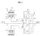
- This embodiment is an example of a two-speed gear transmission that is equipped with a combination of a magnetic-particle-type brake 10 and a planetary gear set 20.
- the magnetic-particle-type brake 10 has a fixed stationary outer member 11 and an inner member 12 that is fitted on a rotor 13 and is disposed inside the outer member 11 in such manner as to rotate freely.
- An exciting coil 14 that is wound in the circumferential direction is housed inside the circumferential wall of the outer member 11, and electromagnetic powder 15 intervenes between the outer member 11 and the inner member 12.
- Electric power is supplied to the exciting coil 14 on the stationary side from the electric power source 16 through the electric power line 17.
- a ring gear 21 is so linked to an input shaft 2 as to form a single piece and also so linked to one rotary member 31 of an oil hydraulic clutch 30 as to form a single piece while a sun gear 22 is linked to the rotor 13 of the magnetic-particle-type electromagnetic brake 10 via a one-way clutch 5.
- the planetary gear 23 is linked to another rotary member 32 of the oil hydraulic clutch 30 via a carrier 24 and the rotary member 32 is so linked to an output shaft 3 as to form a single piece.
- both the inner member 12 of the magnetic-particle-type electromagnetic brake 10 and sun gear 22 that links to the inner member 12 rotate freely, wherein, although the rotative force of the input shaft 2 rotates the ring gear 21, rotations of the ring gear 21 are transmitted to the load-less and freely-rotating sun gear 22 via the planetary gear 23 and the sun gear 22 idles, revolving reverse with the rotor 13, via the one-way clutch 5.
- the planetary gear 23 rotates on its own axis and does not revolve to orbit, and thus the motive power is not transmitted to the output shaft 3 via the carrier 24 and the rotary member 32 of the oil hydraulic clutch 30 to remain in a neutral state.
- the rotative force of the input shaft 2 causes the ring gear 21 to rotate, and the planetary gear 23, rotating on its own axis, revolves between the ring gear 21 and the sun gear 22 that is prohibited from reverse rotations and rotates the carrier 24 to effect low-speed rotations of the output shaft 3, incorporating the rotary member 32 of the oil hydraulic clutch 30.
- the planetary gear set 20 When the oil hydraulic clutch 30 enters the engagement state, the planetary gear set 20 is enabled to rotate as a whole planetary gear set 20 wherein the ring gear 21 and the carrier 24 are linked to form a single piece while the rotative force of the input shaft 2 effects high-speed rotations of the output shaft 3, incorporating the planetary gear set 20 that is separated by the one-way clutch 5, since the input shaft 2 is directly linked to the output shaft 3.
- the two-speed gear transmission 1 according to the invention can form two speed ranges, which are the low-speed range and the high-speed range besides the neutral.
- Magnetic-particle-type electromagnetic brake 10 enables fast and smooth transition from the neutral state to the low-speed range or to the high-speed range.
- the electric power supply to the exciting coil 14 since the outer member 11 of the magnetic-particle-type electromagnetic brake 10 is fastened to be in the stationary state and the exciting coil 14 is disposed on the outer member 11, the electric power is supplied from the electric power source 16 to the exciting coil 14 directly through the electric power line 17, which requires no electric contact parts that intervene in the electric power line 17, such as a slip ring and a brush.
- Fig. 2 shows a simplified block diagram of a control system for an automotive transmission that incorporates the above-described two-speed gear transmission 1 in a drive range thereof.
- the control of the transmission is carried out by an electronic control unit ECU 50; after detected vehicle velocity values V from a vehicle velocity sensor 51, detected throttle valve opening rate values ⁇ th from a throttle valve opening sensor 52 and detected engine revolving speed values NE are respectively input to the ECU 50 and processed, operating command signals are output to the electromagnetic brake 10 and oil hydraulic clutch 30 to carry out the gear change control.
- the ECU 50 comprises a gear change map storing means 55 for storage of gear change maps in advance.
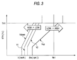
- Fig. 3 shows a gear change map that is stored by the gear change map storing means 55 (a map wherein gear change positions are designated in advance, according to the vehicle velocities and throttle valve opening rates or accelerator opening rates).
- the vehicle velocity V (Km/h) and the engine revolving speed (rpm) are expressed on the horizontal axis while the throttle valve opening rates ⁇ th (%) are expressed on the vertical axis in the map, wherein a polygonal line Vup (gear change line) shows a threshold value at a speed-increasing gear shift from a low-speed range to a high-speed range while a polygonal line Vdown (gear change line) shows a threshold value at a speed-decreasing gear shift from a high-speed range to a low-speed range, and the oil hydraulic clutch 30 is controlled with reference to the lines Vup and Vdown.
- the oil hydraulic clutch 30 When the vehicle velocity V and the throttle valve opening rate ⁇ th change to pass the line Vup from the left to the right, the oil hydraulic clutch 30 is engaged for speed-increasing gear shift from the low-speed range to the high-speed range and, when they pass the line Vdown from the right to the left, the oil hydraulic clutch 30 is disengaged for speed-decreasing gear shift from the high-speed range to the low-speed range.
- the line V1 and the line V2 on the high vehicle velocity side (the right-hand side) of the line Vdown are threshold values for the electromagnetic brake 10 (gear change prediction lines), where the electromagnetic brake 10 is engaged in advance with prediction of the speed-decreasing gear shift before the speed-decreasing gear shift at disengagement of the oil hydraulic clutch 30, when the vehicle velocity V and the throttle valve opening rate ⁇ th change to shift from the right to the left.
- the vehicle velocity is in the relationship of Vdown ⁇ V1 ⁇ V2 ⁇ Vup, and each of the lines are preliminarily set up on the map.
- the throttle valve opening rate TH1 in Fig. 3 is a predetermined high throttle valve opening rate (for example, 75%) and the engine revolving speed Ne1 is a predetermined high engine revolving speed (for example, 5,000 rpm).
- the gear change map storing means 55 in the ECU 50 stores the above-described gear change map.
- the ECU 50 includes a gear change predicting means 56, and the gear change predicting means 56 predicts gear changes with reference to the vehicle velocity V and the throttle valve opening rate ⁇ th on the gear change map.
- the ECU 50 includes also a heavy load determining means 57, and the heavy load determining means 57 determines whether a heavy load state is present or not, with reference to the throttle valve opening rates ⁇ th or the engine revolving speeds Ne. That is, whether the throttle valve opening rate ⁇ th exceeds the high throttle valve opening rate TH1 or not, or whether the engine revolving speed Ne exceeds the high engine revolving speed Ne1 or not is determined.
- the results of determination by the high load determining means 57 are also input to the gear change state selecting means 58.
- the gear change state selecting means 58 selects the gear change state, based on the results of prediction by the gear change predicting means 56 and the results of determination by the heavy load determining means 57, also selecting the gear change state, based on the vehicle velocity V and the throttle valve opening rate ⁇ th with reference to the gear change map, and then outputs command signals to a brake operation control means 59 and a clutch operation control means 60.
- the oil hydraulic clutch 30 is controlled as described above, based on the lines Vup and Vdown which are the gear change lines on the gear change map in Fig. 3.
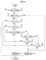
- step S1 whether the gears are being changed or not is determined first (step S1), and the control is cancelled in case the gears are in the course of change, but the sequence proceeds to step S2 in case the gear change has been completed, whereat whether the selected shift range is D (drive) or R (rear) is determined; the sequence jumps to step S10 in case the selected range is neither DRIVE nor REAR, whereat, after flow of electric current Ipb to the electromagnetic brake 10 is shut off, the electromagnetic brake 10 is disengaged.
- step S2 In case the shift range selected at step S2 is either D (drive) or R (rear), the sequence proceeds to step S3, whereat whether the throttle valve opening rate ⁇ th is in the heavy load state of the high throttle valve opening rate TH1 or higher is determined. In case in the heavy load state, the sequence proceeds to step S9 whereat electric current Ipb is supplied to the electromagnetic brake 10 to cause the electromagnetic brake 10 to be engaged.
- step S3 the sequence proceeds to step S4 to determine whether the engine revolving speed Ne is in the heavy load state of the high engine revolving speed Ne1 or higher or not. In case of the heavy load, the sequence jumps to step S9 for flow of the electric current Ipb to cause the electromagnetic brake 10 to be engaged.
- step S4 the sequence proceeds from step S4 to step S5 to determine whether the low-speed range is selected or not.
- step S9 whereat the electric current Ipb is supplied to the electromagnetic to maintain the engagement state of the electromagnetic brake 10.
- step S6 On determination that the low-speed range is not selected, the sequence proceeds to step S6, whereat whether absolute value of time rate ⁇ ⁇ th (change amount per second) of the throttle valve opening rate ⁇ th is smaller than a predetermined change rate ⁇ TH2 (for example, 30%) or not is determined.
- a predetermined change rate ⁇ TH2 for example, 30%
- step S7 the sequence proceeds to step S7, whereat whether the vehicle velocity V is smaller than V1 or not (whether the vehicle velocity V is on the left side of the line V1 that is the gear change prediction line or not) is determined. In case it is smaller, with prediction of a gear change on an approach to the line Vdown whereon the vehicle velocity V changes from the high-speed to the low-speed while in the high-speed range, the sequence proceeds to step S9 whereat electric current Ipb is supplied to the electromagnetic brake 10 to effect the engagement of the electromagnetic brake 10.
- step S10 the sequence proceeds to step S10, whereat supply of the electric current Ipb is shut off with determination that a gear change has not been predicted yet and disengagement of the electromagnetic brake 10 is effected.
- Step S6 On determination that the change of the throttle valve opening rate ⁇ th is large (
- step S10 the sequence proceeds to step S10, whereat supply of the electric current I pb is shut off with determination that a gear change has not been predicted yet and disengagement of the electromagnetic brake 10 is effected.
- step S5 Since the low-speed range has been selected after the engagement of the electromagnetic brake 10 and the succeeding engagement of the oil hydraulic clutch 30, the sequence jumps from step S5 to step S9 whereat the electrification of the electromagnetic brake 10 is maintained and the engagement state is held.
- the electromagnetic brake 10 is engaged before disengagement of the oil hydraulic clutch 30 when the gear change from the high-speed to the low-speed range is predicted, based on the gear change prediction lines V1 and V2 in the gear change map, the engagement of the electromagnetic brake 10 is effected without fail when the oil hydraulic clutch 30 is disengaged and thus the blow-up at the engine is prevented.
- step S5 the sequence proceeds from step S5 to step S6 on gear change to the high-speed range with the engagement of the oil hydraulic clutch 30. Then, since the electric current flow to the electromagnetic brake 10 is shut off only after the vehicle velocity V enters the right-hand side of the line V1 or the line V2 at step S7 or at step S8, electric flow to the electromagnetic brake 10 can be shut off only after simplified confirmation of the full engagement of the oil hydraulic clutch 30.
- the electric current flow to the electromagnetic brake except in the low-speed range is shut off to thereby effect improvement in the fuel cost.
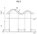
- This mode of embodiment uses calculated vehicle velocity values VNe for gear change prediction, which are obtained from such as gear ratios by calculations based on the engine revolving speed Ne.
- the calculated vehicle velocity values VNe are based on the engine revolving speed Ne and thus any change in the vehicle velocity becomes apparent before the vehicle velocity values V that are detected by the vehicle velocity sensor 51.
- the upper part of the chart in Fig. 5 is an example to show the state described above, wherein the calculated vehicle velocity value Vne changes before the vehicle velocity V.
- the lower part of the chart in Fig. 5 shows the "on” and “off” states of the electromagnetic brake 10 of the example shown in the upper part of the chart.
- FIG. 6 shows the control procedures of the electromagnetic brake 10.
- Steps S11 through S15 in this flowchart are the same as steps S1 through S5 on the flowchart in above-described Fig. 4 and steps S18 and S19 correspond to the above-described steps S9 and S10.
- step S15 the sequence proceeds to step S16, whereat whether calculated vehicle velocity value VNe is smaller than the predetermined vehicle velocity value Va or not is determined. In case it is smaller, with prediction of change in vehicle velocity V by range change from the high-speed to the low-speed, the sequence proceeds to step S18 whereat electric current Ipb is supplied to the electromagnetic brake 10 for engagement of the electromagnetic brake 10.
- step S17 whereat whether the vehicle velocity V is smaller than the vehicle velocity value Va or not is determined. While it is smaller, the sequence proceeds to step S18 whereat the engagement of the electromagnetic brake 10 is maintained, but, in case the vehicle velocity V become larger than the vehicle velocity value Va, the sequence proceeds to step S19 whereat, for the first time, flow of electric current Ipb to the electromagnetic brake 10 is shut off to effect disengagement of the electromagnetic brake 10.
- the electromagnetic brake 10 is engaged before disengagement of the oil hydraulic clutch 30.
- the engagement of the electromagnetic brake 10 is secured before the oil hydraulic clutch 30 is disengaged, to thereby prevent the blow-up at engine.
- step S15 the sequence proceeds from step S15 to step S16 on gear change to the high-speed range with the engagement of the oil hydraulic clutch 30 and then, shut-off of the electric current flow to the electromagnetic brake 10 is effected only after the vehicle velocity V becomes larger than the predetermined vehicle velocity value Va at step S17. Accordingly, the electric current flow to the electromagnetic brake 10 is shut off after simplified confirmation of the full engagement of the oil hydraulic clutch 30.
- the above-described modes of embodiments relate to the two-speed gear transmission
- another set of planetary gear set at a rear range of the present planetary gear set for the two-speed gear transmission so as to comprise a clutch that can engage and disengage an input shaft and an output shaft of the rear-range set to provide a four-speed-ranged transmission, which includes a first speed range of low-speed range for the front and rear ranges, a second speed range of one high-speed range for the front range and one low-speed range for the rear range, a reversal third speed range of one low-speed range for the front range and one high-speed range for the rear range and a fourth speed range of high-speed ranges respectively for the front and rear ranges.
- Figs. 7 and 8 show gear change maps for the four-gear transmission.
- Fig. 7 is a gear change map at the time of speed-increasing gear shift, wherein set up are lines V12, V23 and V34 respectively for gear changes, from the first speed range to the second speed range, from the second speed range to the third speed range and from the third speed range to the fourth speed range.
- gear change prediction line V23A and V23B are set up in advance in front (low-vehicle-velocity side) of the gear change line.
- an advanced electrification of the electromagnetic brake 10 to effect the engagement state in case where a gear change with the vehicle velocity V beyond the lines V23A and V23B is predicted enables prevention of the engine blow-up.
- the gear change prediction lines V43A and V43B and the gear change prediction lines 21A and 21B are drawn respectively before (on the high vehicle velocity side of) the gear change lines V43 and V21 in advance.
- ring gear is linked to the electromagnetic brake via the one-way clutch, with a sun gear as the input and the carrier that is linked to the planetary gear as the output, so that the input and the output are engaged and disengaged by the oil hydraulic clutch.
- the electromagnetic brakes that are involved in the above described modes of embodiment are the magnetic-particle-type electromagnetic brakes
- the brake apparatus is not limited to the above but non-magnetic-particle-type electromagnetic brakes, oil hydraulic brakes (dry-type, wet-type, single-plate-type and multi-plate-type are also available) and pneumatic brakes can also be used.
- the oil hydraulic clutch may be replaced by an electromagnetic clutch.
- a determining means for determination of up-slopes and down-slopes may be provided to effect the maintenance of the brake engagement state with a prediction of frequent gear changes in case of determination on travelling over an up-slope or a down-slope.
- a control apparatus for a transmission that links an input member for reception of rotative drive force to a gear element of a planetary gear set including three gears, an output member to another gear element of the same planetary gear set and a rotary member to the other gear of the same planetary gear set, wherein a brake 10 causes the rotary member and a stationary member to be engaged with and disengaged from each other while a clutch 30 causes the input member and the output member to be engaged with and disengaged from each other, and that comprises a first speed range wherein the brake 10 is engaged while the clutch 30 is disengaged and a second speed range wherein the clutch 30 is engaged; and wherein a gear change predicting means 56 for predicting speed change between the first speed range and the second speed range is involved and brake control means 58 and 59 for control of the brake 10 cause the brake 10 to be engaged before operation of the clutch 30 when the gear change predicting means 56 predicts a speed change.
Landscapes
- Engineering & Computer Science (AREA)
- General Engineering & Computer Science (AREA)
- Mechanical Engineering (AREA)
- Control Of Transmission Device (AREA)
- Hydraulic Clutches, Magnetic Clutches, Fluid Clutches, And Fluid Joints (AREA)
- Structure Of Transmissions (AREA)
Abstract
Description
- The present invention relates to a control apparatus for a transmission that uses a planetary gear set.
- An example of such a transmission is described on the Japanese Patent Unexamined Publication No. Hei.8-338486.
- That has the same mechanical structure as the present invention has and, in an embodiment thereof (see Fig. 1 for an embodiment of the invention), a ring gear 21 of a
planetary gear set 20 is so linked to an input shaft as to form a single piece and is also so linked to one rotary member 31 of the oilhydraulic clutch 30 as to form a single piece while asun gear 22 is linked to arotor 13 of the magnetic-particle-type electromagnetic brake (electromagnetic brake) 10 via a one-way clutch 5. Aplanetary gear 23 is linked to the otherrotary member 32 of the oilhydraulic clutch 30 via acarrier 24 and therotary member 32 is linked to anoutput shaft 3. - When the
electromagnetic brake 10 is engaged while the oilhydraulic clutch 30 is disengaged, the first speed range is selected to effect low-speed rotations of theoutput shaft 3 and, when theelectromagnetic brake 10 is disengaged while the oilhydraulic clutch 30 is engaged, the second speed range is selected to effect high-speed rotations of theoutput shaft 3. - At the gear change from the second speed range to the first speed range, the oil
hydraulic clutch 30 is disengaged but, in case of delay in the engagement of theelectromagnetic brake 10, an abrupt loss of load causes the engine to blow up. - Additionally, in case of an imperfect engagement of the
electromagnetic brake 10, disengagement of the oilhydraulic clutch 30 is liable to cause the engine to blow up. - The present invention, considering such problems as described above, is purposed to provide a control apparatus for the transmission that enables prevention of blowing up at the engine when at the time of gear change.
- For achievement of the above-described purposes, the invention provides a control apparatus for a transmission that links an input member for reception of rotative drive force to a gear element of a planetary gear set including three gears, an output member to another gear element of the same planetary ger set and a rotary member to the other gear of the same planetary gear set, wherein a brake causes the rotary member and a stationary member to be engaged with and disengaged from each other while a clutch causes the input member and the output member to be engaged with and disengaged from each other, and that comprises a first speed range wherein the brake is engaged while the clutch is disengaged and a second speed range wherein the clutch is engaged; and wherein a gear change predicting means for predicting gear change between the first speed range and the second speed range is involved and a brake control means for control of the brake causes the brake to be engaged before operation of the clutch when the gear change predicting means predicts a gear change.
- The gear change prediction by the gear change predicting means enables engagement of the brake before the clutch is operated and thus the blow-up at the engine is prevented without fail since the brake has already been engaged when the clutch is operated.
- In the second aspect of the invention, the transmission control apparatus in accordance with the first aspect of the invention is characterized by that the brake control means causes engagement of the brake before disengagement of the clutch when the gear change predicting means predicts a gear change from the second speed range to the first speed range.
- On prediction of the gear change from the second speed range to the first speed range by the gear change predicting means, the brake is engaged before the disengagement of the clutch, and thus the blow-up at the engine is prevented without fail since the brake has already been engaged when the clutch is disengaged.
- In the third aspect of the invention, the transmission control apparatus in accordance with the first or the second aspect of the invention is characterized by that the gear change predicting means predicts a gear change, based on vehicle velocities and throttle valve opening rates.
- The engagement of the brake on prediction of the gear change by the gear change predicting means before the clutch is operated to change the gears, based on the vehicle velocities and the throttle valve opening rates, enables prevention of the blow-up at the engine.
- In the fourth aspect of the invention, the transmission control apparatus in accordance with the first or the second aspect of the invention is characterized by that the gear change predicting means predicts a gear change, based on engine revolving speeds.
- The gear change can be predicted by the gear change predicting means, based on the engine revolving speeds that change before the vehicle velocities that are the gear change parameters, and thus the engagement of the brake on the prediction enables prevention of the blow-up at the engine.
- In the fifth aspect of the invention, the transmission control apparatus in accordance with the first or the second aspect of the invention is characterized by that the brake control means is a magnetic-particle-type electromagnetic brake that is enabled to fasten a rotary member onto the stationary member through control of energization amount when an exciting coil provided on the stationary element is energized.
- The magnetic-particle-type electromagnetic brake, having an exciting coil on either the outer member side or the inner member side that rotate relatively, carries out the torque transmission with formation of magnetic particle chains through magnetization of the magnetic particles of the electromagnetic powder that intervenes between the outer member and the inner member when a magnetic field is generated by electrification of the exciting coil.
- Regulation of the electrification amount for electrification of the exciting coil on the magnetic-particle-type electromagnetic brake enables smooth and immediate engagement and disengagement of the brake through transmission torque control by changing an intensity of the magnetic field.
- In the sixth aspect of the invention, the transmission control apparatus in accordance with the first or the second aspect of the invention is characterized by that a heavy load determining means for determination of a heavy load state at an engine for supply of drive force to the input member is provided and that the brake control means so controls with priority as to prohibit disengagement of the brake on determination of the heavy load state by the heavy load determining means.
- When the engine is in the heavy load state, since the brake operations may happen to delay behind a change in the engine torque, prohibition of the brake disengagement for maintenance of the engagement state with priority enables prevention of the blow-up at the engine without fail.
- In the seventh aspect of the invention, the transmission control apparatus in accordance with the sixth aspect of the invention is characterized by that the brake control means so controls as to engage the brake on determination of the heavy load state in the engine by the heavy load determining means in the course of disengagement of the brake.
- Since the heavy load state at the engine can cause delay in the brake operations behind a change in the engine torque, the engagement of the brake, in case the brake is in the course of disengagement, enables prevention of the blow-up at the engine without fail.
-
- Fig. 1 shows an outlined structure of a two-speed gear transmission related to an embodiment of the invention;
- Fig. 2 shows an outlined block diagram of a control system for automotive transmission that incorporates the same two-speed-ranged transmission;
- Fig. 3 shows a gear change map;
- Fig. 4 is a flowchart to show operational controls of the electromagnetic brake;
- Fig. 5 is a diagrammatic chart to show controls of the electromagnetic brake, which is related to another mode of embodiment;
- Fig. 6 is a flowchart for the same controls;
- Fig. 7 shows a gear change map at the time of speed-increasing gear shifts for the four-gear transmission; and
- Fig. 8 shows a gear change map at the time of speed-decreasing gear shifts for the same.
-
- With references to Figs. 1 through 4, a mode of embodiment pertaining to the present invention is now described.
- This embodiment is an example of a two-speed gear transmission that is equipped with a combination of a magnetic-particle-
type brake 10 and aplanetary gear set 20. - The magnetic-particle-
type brake 10 has a fixed stationaryouter member 11 and aninner member 12 that is fitted on arotor 13 and is disposed inside theouter member 11 in such manner as to rotate freely. - An
exciting coil 14 that is wound in the circumferential direction is housed inside the circumferential wall of theouter member 11, andelectromagnetic powder 15 intervenes between theouter member 11 and theinner member 12. - Electric power is supplied to the
exciting coil 14 on the stationary side from theelectric power source 16 through theelectric power line 17. - In the planetary gear set 20, a ring gear 21 is so linked to an
input shaft 2 as to form a single piece and also so linked to one rotary member 31 of an oilhydraulic clutch 30 as to form a single piece while asun gear 22 is linked to therotor 13 of the magnetic-particle-typeelectromagnetic brake 10 via a one-way clutch 5. - The
planetary gear 23 is linked to anotherrotary member 32 of the oilhydraulic clutch 30 via acarrier 24 and therotary member 32 is so linked to anoutput shaft 3 as to form a single piece. - In the
transmission 1 that has a structure as described above, so long as both the magnetic-particle-typeelectromagnetic brake 10 and the oilhydraulic clutch 30 are disengaged, both theinner member 12 of the magnetic-particle-typeelectromagnetic brake 10 andsun gear 22 that links to theinner member 12 rotate freely, wherein, although the rotative force of theinput shaft 2 rotates the ring gear 21, rotations of the ring gear 21 are transmitted to the load-less and freely-rotatingsun gear 22 via theplanetary gear 23 and thesun gear 22 idles, revolving reverse with therotor 13, via the one-way clutch 5. - Therefore, the
planetary gear 23 rotates on its own axis and does not revolve to orbit, and thus the motive power is not transmitted to theoutput shaft 3 via thecarrier 24 and therotary member 32 of the oilhydraulic clutch 30 to remain in a neutral state. - With the
exciting coil 14 on the magnetic-particle-typeelectromagnetic brake 10 energized in this state, a magnetic field is generated to effect magnetization and chaining of the magnetic particles of the electromagnetic powder and, when theinner member 12 is finally linked to theouter member 11 on the stationary side, theinner member 12 is fastened together with therotor 13 so that thesun gear 22 is prohibited from reverse rotations via the one-way clutch 5. - The rotative force of the
input shaft 2 causes the ring gear 21 to rotate, and theplanetary gear 23, rotating on its own axis, revolves between the ring gear 21 and thesun gear 22 that is prohibited from reverse rotations and rotates thecarrier 24 to effect low-speed rotations of theoutput shaft 3, incorporating therotary member 32 of the oilhydraulic clutch 30. - When the oil
hydraulic clutch 30 enters the engagement state, theplanetary gear set 20 is enabled to rotate as a whole planetary gear set 20 wherein the ring gear 21 and thecarrier 24 are linked to form a single piece while the rotative force of theinput shaft 2 effects high-speed rotations of theoutput shaft 3, incorporating theplanetary gear set 20 that is separated by the one-way clutch 5, since theinput shaft 2 is directly linked to theoutput shaft 3. - As described above, the two-
speed gear transmission 1 according to the invention can form two speed ranges, which are the low-speed range and the high-speed range besides the neutral. - Use of the magnetic-particle-type
electromagnetic brake 10 enables fast and smooth transition from the neutral state to the low-speed range or to the high-speed range. - As for the electric power supply to the
exciting coil 14, since theouter member 11 of the magnetic-particle-typeelectromagnetic brake 10 is fastened to be in the stationary state and theexciting coil 14 is disposed on theouter member 11, the electric power is supplied from theelectric power source 16 to theexciting coil 14 directly through theelectric power line 17, which requires no electric contact parts that intervene in theelectric power line 17, such as a slip ring and a brush. - Fig. 2 shows a simplified block diagram of a control system for an automotive transmission that incorporates the above-described two-
speed gear transmission 1 in a drive range thereof. - The control of the transmission is carried out by an electronic
control unit ECU 50; after detected vehicle velocity values V from avehicle velocity sensor 51, detected throttle valve opening rate values th from a throttlevalve opening sensor 52 and detected engine revolving speed values NE are respectively input to theECU 50 and processed, operating command signals are output to theelectromagnetic brake 10 and oilhydraulic clutch 30 to carry out the gear change control. - The ECU 50 comprises a gear change map storing means 55 for storage of gear change maps in advance. Fig. 3 shows a gear change map that is stored by the gear change map storing means 55 (a map wherein gear change positions are designated in advance, according to the vehicle velocities and throttle valve opening rates or accelerator opening rates).
- The vehicle velocity V (Km/h) and the engine revolving speed (rpm) are expressed on the horizontal axis while the throttle valve opening rates th (%) are expressed on the vertical axis in the map, wherein a polygonal line Vup (gear change line) shows a threshold value at a speed-increasing gear shift from a low-speed range to a high-speed range while a polygonal line Vdown (gear change line) shows a threshold value at a speed-decreasing gear shift from a high-speed range to a low-speed range, and the oil
hydraulic clutch 30 is controlled with reference to the lines Vup and Vdown. - When the vehicle velocity V and the throttle valve opening rate th change to pass the line Vup from the left to the right, the oil
hydraulic clutch 30 is engaged for speed-increasing gear shift from the low-speed range to the high-speed range and, when they pass the line Vdown from the right to the left, the oilhydraulic clutch 30 is disengaged for speed-decreasing gear shift from the high-speed range to the low-speed range. - The line V1 and the line V2 on the high vehicle velocity side (the right-hand side) of the line Vdown are threshold values for the electromagnetic brake 10 (gear change prediction lines), where the
electromagnetic brake 10 is engaged in advance with prediction of the speed-decreasing gear shift before the speed-decreasing gear shift at disengagement of the oilhydraulic clutch 30, when the vehicle velocity V and the throttle valve opening rate th change to shift from the right to the left. - The vehicle velocity is in the relationship of Vdown < V1 < V2 < Vup, and each of the lines are preliminarily set up on the map.
- The throttle valve opening rate TH1 in Fig. 3 is a predetermined high throttle valve opening rate (for example, 75%) and the engine revolving speed Ne1 is a predetermined high engine revolving speed (for example, 5,000 rpm).
- The gear change map storing means 55 in the ECU 50 stores the above-described gear change map.
- As shown in Fig. 2, the
ECU 50 includes a gear change predicting means 56, and the gear change predicting means 56 predicts gear changes with reference to the vehicle velocity V and the throttle valve opening rate th on the gear change map. - That is, whether transition of the vehicle velocity V and the throttle valve opening rate th from the right to the left passes the gear change prediction line V1 or V2 or not is determined to predict the gear change, and the prediction results are input to the gear change
state selecting means 58. - The
ECU 50 includes also a heavyload determining means 57, and the heavyload determining means 57 determines whether a heavy load state is present or not, with reference to the throttle valve opening rates th or the engine revolving speeds Ne. That is, whether the throttle valve opening rate th exceeds the high throttle valve opening rate TH1 or not, or whether the engine revolving speed Ne exceeds the high engine revolving speed Ne1 or not is determined. - The results of determination by the high
load determining means 57 are also input to the gear changestate selecting means 58. - The gear change state selecting means 58 selects the gear change state, based on the results of prediction by the gear change predicting means 56 and the results of determination by the heavy
load determining means 57, also selecting the gear change state, based on the vehicle velocity V and the throttle valve opening rate th with reference to the gear change map, and then outputs command signals to a brake operation control means 59 and a clutch operation control means 60. - Based on the command signals, operations of the
electromagnetic brake 10 are controlled by the brake operation control means 59 and operation of the oil hydraulic clutch 30 are controlled by the clutch operation control means 60. - The oil
hydraulic clutch 30 is controlled as described above, based on the lines Vup and Vdown which are the gear change lines on the gear change map in Fig. 3. - Operations of the
electromagnetic brake 10 are controlled in compliance with a flowchart in Fig. 4. - On reference to the flowchart, whether the gears are being changed or not is determined first (step S1), and the control is cancelled in case the gears are in the course of change, but the sequence proceeds to step S2 in case the gear change has been completed, whereat whether the selected shift range is D (drive) or R (rear) is determined; the sequence jumps to step S10 in case the selected range is neither DRIVE nor REAR, whereat, after flow of electric current Ipb to the
electromagnetic brake 10 is shut off, theelectromagnetic brake 10 is disengaged. - In case the shift range selected at step S2 is either D (drive) or R (rear), the sequence proceeds to step S3, whereat whether the throttle valve opening rate th is in the heavy load state of the high throttle valve opening rate TH1 or higher is determined. In case in the heavy load state, the sequence proceeds to step S9 whereat electric current Ipb is supplied to the
electromagnetic brake 10 to cause theelectromagnetic brake 10 to be engaged. - In case the throttle opening rate th at step S3 is less than the high throttle valve opening rate TH1, the sequence proceeds to step S4 to determine whether the engine revolving speed Ne is in the heavy load state of the high engine revolving speed Ne1 or higher or not. In case of the heavy load, the sequence jumps to step S9 for flow of the electric current Ipb to cause the
electromagnetic brake 10 to be engaged. - That is, since whether the engine is in the heavy load state or not is determined from the throttle valve opening rate th and the engine revolving speed Ne at steps S3 and S4 so that the
electromagnetic brake 10 will be engaged by electrification of theelectromagnetic brake 10 in case the heavy load state is present, engine blow-up that results from delay in the control torque for theelectromagnetic brake 10 behind the engine torque transition can be effectively prevented. - In case the heavy load state is not present, the sequence proceeds from step S4 to step S5 to determine whether the low-speed range is selected or not.
- In case the low-speed range is selected, the sequence proceeds to step S9, whereat the electric current Ipb is supplied to the electromagnetic to maintain the engagement state of the
electromagnetic brake 10. - On determination that the low-speed range is not selected, the sequence proceeds to step S6, whereat whether absolute value of time rate Δ th (change amount per second) of the throttle valve opening rate th is smaller than a predetermined change rate Δ TH2 (for example, 30%) or not is determined.
- That is, whether the change of the throttle valve opening rate is small or great or not is determined.
- In case the change in the throttle valve opening rate is small, the sequence proceeds to step S7, whereat whether the vehicle velocity V is smaller than V1 or not (whether the vehicle velocity V is on the left side of the line V1 that is the gear change prediction line or not) is determined. In case it is smaller, with prediction of a gear change on an approach to the line Vdown whereon the vehicle velocity V changes from the high-speed to the low-speed while in the high-speed range, the sequence proceeds to step S9 whereat electric current Ipb is supplied to the
electromagnetic brake 10 to effect the engagement of theelectromagnetic brake 10. - In case the vehicle velocity V is greater than V1, the sequence proceeds to step S10, whereat supply of the electric current Ipb is shut off with determination that a gear change has not been predicted yet and disengagement of the
electromagnetic brake 10 is effected. - On determination that the change of the throttle valve opening rate th is large (|Δ th|≥ Δ TH2) in Step S6, the sequence proceeds to step S8 whereat whether the vehicle velocity V is smaller than V2 (whether the vehicle velocity V is on the left side of the gear change prediction line V2 in the gear change map in Fig. 3 or not) is determined. In case it is smaller, with prediction of a gear change on an approach to the line Vdown whereon the vehicle velocity V changes from the high-speed to the low-speed, while in the high-speed range, the sequence proceeds to step S9 whereat electric current Ipb is supplied to the
electromagnetic brake 10 to effect the engagement of theelectromagnetic brake 10. - In case the vehicle velocity V is greater than V2, the sequence proceeds to step S10, whereat supply of the electric current I pb is shut off with determination that a gear change has not been predicted yet and disengagement of the
electromagnetic brake 10 is effected. - In case the change in the throttle valve opening rate th is great, a fast approach to the line Vdown whereon the vehicle velocity V changes from the high-speed to the low-speed while in the high-speed range can be predicted, the engagement of the
electromagnetic brake 10 is effected further in advance with the line V2 as the gear change prediction line, which lies in the zone closer to the front (the right-hand side) than the line V1 in the gear change map. - Since the low-speed range has been selected after the engagement of the
electromagnetic brake 10 and the succeeding engagement of the oilhydraulic clutch 30, the sequence jumps from step S5 to step S9 whereat the electrification of theelectromagnetic brake 10 is maintained and the engagement state is held. - As described above, since the
electromagnetic brake 10 is engaged before disengagement of the oil hydraulic clutch 30 when the gear change from the high-speed to the low-speed range is predicted, based on the gear change prediction lines V1 and V2 in the gear change map, the engagement of theelectromagnetic brake 10 is effected without fail when the oilhydraulic clutch 30 is disengaged and thus the blow-up at the engine is prevented. - In a case of transition from the low-speed to the high-speed range, the sequence proceeds from step S5 to step S6 on gear change to the high-speed range with the engagement of the oil
hydraulic clutch 30. Then, since the electric current flow to theelectromagnetic brake 10 is shut off only after the vehicle velocity V enters the right-hand side of the line V1 or the line V2 at step S7 or at step S8, electric flow to theelectromagnetic brake 10 can be shut off only after simplified confirmation of the full engagement of the oilhydraulic clutch 30. - The electric current flow to the electromagnetic brake except in the low-speed range is shut off to thereby effect improvement in the fuel cost.
- Although the above-described mode of embodiment controls the
electromagnetic brake 10 with prediction of gear change from the high-speed to the low-speed range, which is based on the gear change prediction lines that are drawn in advance on the gear change map, another method for control of theelectromagnetic brake 10 with gear change prediction is described now with references to Figs. 5 and 6. - This mode of embodiment uses calculated vehicle velocity values VNe for gear change prediction, which are obtained from such as gear ratios by calculations based on the engine revolving speed Ne.
- The calculated vehicle velocity values VNe are based on the engine revolving speed Ne and thus any change in the vehicle velocity becomes apparent before the vehicle velocity values V that are detected by the
vehicle velocity sensor 51. - The upper part of the chart in Fig. 5 is an example to show the state described above, wherein the calculated vehicle velocity value Vne changes before the vehicle velocity V. The lower part of the chart in Fig. 5 shows the "on" and "off" states of the
electromagnetic brake 10 of the example shown in the upper part of the chart. - A flowchart in Fig. 6 shows the control procedures of the
electromagnetic brake 10. - Steps S11 through S15 in this flowchart are the same as steps S1 through S5 on the flowchart in above-described Fig. 4 and steps S18 and S19 correspond to the above-described steps S9 and S10.
- In case it is determined at step S15 that a low-speed range is not selected, the sequence proceeds to step S16, whereat whether calculated vehicle velocity value VNe is smaller than the predetermined vehicle velocity value Va or not is determined. In case it is smaller, with prediction of change in vehicle velocity V by range change from the high-speed to the low-speed, the sequence proceeds to step S18 whereat electric current Ipb is supplied to the
electromagnetic brake 10 for engagement of theelectromagnetic brake 10. - In case the calculated vehicle velocity value VNe is larger than the predetermined vehicle velocity value Va, the sequence proceeds to step S17, whereat whether the vehicle velocity V is smaller than the vehicle velocity value Va or not is determined. While it is smaller, the sequence proceeds to step S18 whereat the engagement of the
electromagnetic brake 10 is maintained, but, in case the vehicle velocity V become larger than the vehicle velocity value Va, the sequence proceeds to step S19 whereat, for the first time, flow of electric current Ipb to theelectromagnetic brake 10 is shut off to effect disengagement of theelectromagnetic brake 10.
As described above, in case where a gear change from the high-speed range to the low-speed range is predictable based on the calculated vehicle velocity value VNe, theelectromagnetic brake 10 is engaged before disengagement of the oilhydraulic clutch 30. Thus, the engagement of theelectromagnetic brake 10 is secured before the oilhydraulic clutch 30 is disengaged, to thereby prevent the blow-up at engine. - On the other hand, at transition from the low-speed range to the high-speed range, the sequence proceeds from step S15 to step S16 on gear change to the high-speed range with the engagement of the oil
hydraulic clutch 30 and then, shut-off of the electric current flow to theelectromagnetic brake 10 is effected only after the vehicle velocity V becomes larger than the predetermined vehicle velocity value Va at step S17. Accordingly, the electric current flow to theelectromagnetic brake 10 is shut off after simplified confirmation of the full engagement of the oilhydraulic clutch 30. - Although the above-described modes of embodiments relate to the two-speed gear transmission, it is also possible to include another set of planetary gear set at a rear range of the present planetary gear set for the two-speed gear transmission so as to comprise a clutch that can engage and disengage an input shaft and an output shaft of the rear-range set to provide a four-speed-ranged transmission, which includes a first speed range of low-speed range for the front and rear ranges, a second speed range of one high-speed range for the front range and one low-speed range for the rear range, a reversal third speed range of one low-speed range for the front range and one high-speed range for the rear range and a fourth speed range of high-speed ranges respectively for the front and rear ranges.
- Figs. 7 and 8 show gear change maps for the four-gear transmission.
- Fig. 7 is a gear change map at the time of speed-increasing gear shift, wherein set up are lines V12, V23 and V34 respectively for gear changes, from the first speed range to the second speed range, from the second speed range to the third speed range and from the third speed range to the fourth speed range. At the speed-increasing gear shift from the second speed range of the high-speed range to the third speed range of the low-speed range at the front range, gear change prediction line V23A and V23B are set up in advance in front (low-vehicle-velocity side) of the gear change line.
- Therefore, at the gear change from the second speed range to the third speed range, an advanced electrification of the
electromagnetic brake 10 to effect the engagement state in case where a gear change with the vehicle velocity V beyond the lines V23A and V23B is predicted enables prevention of the engine blow-up. - On the other hand, at the time of speed-decreasing gear shift from the high-speed gear range to the low-speed gear range at the front range, which includes speed-decreasing gear shifts from the fourth speed range to the third speed range and from the second speed range to the first speed range, as shown in Fig. 8, the gear change prediction lines V43A and V43B and the gear change prediction lines 21A and 21B are drawn respectively before (on the high vehicle velocity side of) the gear change lines V43 and V21 in advance.
- In case where speed-decreasing gear shifts of the vehicle velocity V beyond these gear change prediction lines from the fourth speed range to the third speed range and also from the second speed range to the first speed range are predicted, an advanced electrification of the
electromagnetic brake 10 to effect the engagement state enables prevention of the engine blow-up. - Shut-off of the electric current flow Ipb to the electromagnetic brake at the second and fourth speed ranges wherein the front range is in the high-speed range enables improvement in the fuel cost.
- As described above, a simplified control of the four-gear transmission, where the electromagnetic brake is disengaged only in the fourth speed range (not disengaged in the second speed range), is also available.
- Besides the above-described two-speed gear transmission with use of the planetary gear, also possible is a structure wherein ring gear is linked to the electromagnetic brake via the one-way clutch, with a sun gear as the input and the carrier that is linked to the planetary gear as the output, so that the input and the output are engaged and disengaged by the oil hydraulic clutch.
- Also in this structure, since the electromagnetic brake is engaged but the oil hydraulic clutch is disengaged in the low-speed range whereas both the electromagnetic brake and the oil hydraulic clutch are engaged in the high-speed range, the advanced engagement of the electromagnetic brake on prediction of the speed-decreasing gear shift enable prevention of the engine blow-up.
- Although the electromagnetic brakes that are involved in the above described modes of embodiment are the magnetic-particle-type electromagnetic brakes, the brake apparatus is not limited to the above but non-magnetic-particle-type electromagnetic brakes, oil hydraulic brakes (dry-type, wet-type, single-plate-type and multi-plate-type are also available) and pneumatic brakes can also be used.
- In the case of an oil-hydraulic-control-type band brake, however, it is possible to improve the fuel cost by varying the oil pump capacity through on-off switching of the oil pressure, but, since the control of the variable pump requires varying of the oil pump capacity in synchronism, as well as the above-described brake control; considering all that are described above, the use of the electromagnetic brake is the simplest to control and the greatest to effect.
- The oil hydraulic clutch may be replaced by an electromagnetic clutch.
- Additionally, as disclosed in the Japanese national stage publication of international application No. Hei.6-505082, the use of a mechanical-type automatic transmission that engages and disengages the clutch with use of a thrust force of a helical gear and a depressing pressure of a centrifugal weight makes it difficult to predict the actual gear changes.
- That is, since it is necessary to predict a balance between the depressing force of the centrifugal weight that depends on the revolving speed and the thrust force of the helical gear that is based on the engine-side torque, the gear changes cannot be predicted simply from such as the vehicle velocity and the throttle valve opening rate.
- As described above, however, such a control as to maintain the electric current flow to the electromagnetic brake to effect the engagement state at the heavy-load time is extremely effective in prevention of a shock from happening.
- Additionally, a determining means for determination of up-slopes and down-slopes may be provided to effect the maintenance of the brake engagement state with a prediction of frequent gear changes in case of determination on travelling over an up-slope or a down-slope.
- The present disclosure relates to the subject matter contained in Japanese patent application No. Hei.11-137691 filed on May 18, 1999 which is expressly incorporated herein by reference in its entirety.
- A control apparatus for a transmission that links an input member for reception of rotative drive force to a gear element of a planetary gear set including three gears, an output member to another gear element of the same planetary gear set and a rotary member to the other gear of the same planetary gear set, wherein a
brake 10 causes the rotary member and a stationary member to be engaged with and disengaged from each other while a clutch 30 causes the input member and the output member to be engaged with and disengaged from each other, and that comprises a first speed range wherein thebrake 10 is engaged while the clutch 30 is disengaged and a second speed range wherein the clutch 30 is engaged; and wherein a gear change predicting means 56 for predicting speed change between the first speed range and the second speed range is involved and brake control means 58 and 59 for control of thebrake 10 cause thebrake 10 to be engaged before operation of the clutch 30 when the gear change predicting means 56 predicts a speed change.
Claims (6)
- A transmission control apparatus for a transmission, said transmission comprising:a planetary gear set including three gears of first, second and third gears, said first gear linking with an input member in which a rotative drive force is inputted, said second gear linking with an output member, said third gear linking with a rotary member through a one-way clutch;a brake causing said rotary member and a stationary member to be engaged with and disengaged from each other, to thereby obtain the engagement and disengagement of said brake; anda clutch causing said input member and said output member to be engaged with and disengaged from each other, to thereby obtain the engagement and disengagement of said clutch, whereby said transmission includes a first speed range obtained by the engagement of said brake and the disengagement of said clutch, and a second speed range obtained by the engagement of said clutch, said control apparatus comprising:a gear change predicting means for predicting a gear change between said first speed range and said second speed range; anda brake control means for controlling said brake, said brake control means causing said brake to be engaged before an operation of said clutch when said gear change predicting means predicts the gear change.
- The transmission control apparatus claimed in Claim 1, wherein said brake control means causes the engagement of said brake before the disengagement of said clutch when said gear change predicting means predicts the gear change from the second speed range to the first speed range.
- The transmission control apparatus claimed in Claim 1, wherein said gear change predicting means predicts the gear change, based on vehicle velocity and throttle valve opening rate.
- The transmission control apparatus claimed in Claim 1, wherein said gear change predicting means predicts the gear change, based on engine revolving speed.
- The transmission control apparatus claimed in Claim 1, wherein said brake control means is a magnetic-particle-type electromagnetic brake that fastens said rotary member onto said stationary member through control of energization amount when an exciting coil provided on said stationary element is energized.
- The transmission control apparatus claimed in Claim 1, further comprising:a heavy load determining means for determining a heavy load state of an engine supplying of drive force to said input member,
wherein said brake control means controls said brake with priority so as to prohibit the disengagement of said brake when said heavy load determining means determines that said engine is in the heavy load state.7. The transmission control apparatus claimed in Claim 6, wherein said brake control means controls so as to engage said brake when said heavy load determining means determines that said engine is in the heavy load state during the disengagement of said brake.8. The transmission control apparatus claimed in Claim 1, wherein said planetary gear comprises a plurality of planetary gear sets.
Applications Claiming Priority (2)
| Application Number | Priority Date | Filing Date | Title |
|---|---|---|---|
| JP11137691A JP2000329225A (en) | 1999-05-18 | 1999-05-18 | Transmission control device |
| JP13769199 | 1999-05-18 |
Publications (3)
| Publication Number | Publication Date |
|---|---|
| EP1054194A2 true EP1054194A2 (en) | 2000-11-22 |
| EP1054194A3 EP1054194A3 (en) | 2003-05-21 |
| EP1054194B1 EP1054194B1 (en) | 2005-02-09 |
Family
ID=15204561
Family Applications (1)
| Application Number | Title | Priority Date | Filing Date |
|---|---|---|---|
| EP00109612A Expired - Lifetime EP1054194B1 (en) | 1999-05-18 | 2000-05-05 | A transmission control apparatus |
Country Status (6)
| Country | Link |
|---|---|
| EP (1) | EP1054194B1 (en) |
| JP (1) | JP2000329225A (en) |
| CN (1) | CN1273917A (en) |
| DE (1) | DE60017973T2 (en) |
| MY (1) | MY125413A (en) |
| TW (1) | TW426793B (en) |
Families Citing this family (4)
| Publication number | Priority date | Publication date | Assignee | Title |
|---|---|---|---|---|
| CN100425856C (en) * | 2004-08-23 | 2008-10-15 | 株式会社小松制作所 | Work vehicle speed-change control device and speed-change control method |
| JP4349416B2 (en) * | 2006-12-25 | 2009-10-21 | トヨタ自動車株式会社 | Powertrain control device, control method, program for realizing the method, and recording medium recording the program |
| JP5131126B2 (en) * | 2008-09-29 | 2013-01-30 | トヨタ自動車株式会社 | Control device for twin clutch transmission |
| US8371986B2 (en) * | 2010-06-03 | 2013-02-12 | Ford Global Technologies, Llc | Transmission control during park range disengagement |
Citations (3)
| Publication number | Priority date | Publication date | Assignee | Title |
|---|---|---|---|---|
| JPH06505082A (en) | 1990-10-18 | 1994-06-09 | アントーノフ オートモーティブ テクノロジーズ ベスローテン フェンノートシャップ | Automotive transmission |
| JPH08338486A (en) | 1995-06-12 | 1996-12-24 | Honda Motor Co Ltd | Power transmission device |
| JPH11137691A (en) | 1997-07-23 | 1999-05-25 | Appl Ind Medicales & Electroniques Saime:Soc | Outgassing sensors and respiratory equipment |
Family Cites Families (3)
| Publication number | Priority date | Publication date | Assignee | Title |
|---|---|---|---|---|
| JP2822527B2 (en) * | 1990-01-19 | 1998-11-11 | トヨタ自動車株式会社 | Automatic transmission for vehicles |
| JPH08246913A (en) * | 1995-03-03 | 1996-09-24 | Toyota Motor Corp | Automatic transmission control device |
| US5733222A (en) * | 1995-06-02 | 1998-03-31 | Honda Giken Kogyo Kabushiki Kaisha | Power transmission apparatus |
-
1999
- 1999-05-18 JP JP11137691A patent/JP2000329225A/en active Pending
-
2000
- 2000-05-05 EP EP00109612A patent/EP1054194B1/en not_active Expired - Lifetime
- 2000-05-05 DE DE60017973T patent/DE60017973T2/en not_active Expired - Fee Related
- 2000-05-11 MY MYPI20002051A patent/MY125413A/en unknown
- 2000-05-11 TW TW089108994A patent/TW426793B/en not_active IP Right Cessation
- 2000-05-18 CN CN00108596A patent/CN1273917A/en active Pending
Patent Citations (3)
| Publication number | Priority date | Publication date | Assignee | Title |
|---|---|---|---|---|
| JPH06505082A (en) | 1990-10-18 | 1994-06-09 | アントーノフ オートモーティブ テクノロジーズ ベスローテン フェンノートシャップ | Automotive transmission |
| JPH08338486A (en) | 1995-06-12 | 1996-12-24 | Honda Motor Co Ltd | Power transmission device |
| JPH11137691A (en) | 1997-07-23 | 1999-05-25 | Appl Ind Medicales & Electroniques Saime:Soc | Outgassing sensors and respiratory equipment |
Also Published As
| Publication number | Publication date |
|---|---|
| EP1054194B1 (en) | 2005-02-09 |
| DE60017973D1 (en) | 2005-03-17 |
| EP1054194A3 (en) | 2003-05-21 |
| MY125413A (en) | 2006-07-31 |
| CN1273917A (en) | 2000-11-22 |
| DE60017973T2 (en) | 2005-07-07 |
| TW426793B (en) | 2001-03-21 |
| JP2000329225A (en) | 2000-11-30 |
Similar Documents
| Publication | Publication Date | Title |
|---|---|---|
| US10144406B2 (en) | Power transmission apparatus | |
| US6574535B1 (en) | Apparatus and method for active driveline damping with clunk control | |
| US7306064B2 (en) | Hybrid transmission and mode-shift control for hybrid vehicle | |
| US6962550B2 (en) | Control for vehicle including electric motor powered by engine driven generator | |
| JP4063744B2 (en) | Control device for hybrid vehicle | |
| US7219757B2 (en) | Mode transfer control apparatus and method for hybrid vehicle | |
| US7125362B2 (en) | Hybrid powertrain system including smooth shifting automated transmission | |
| US11046299B2 (en) | Methods and system for operating a four wheel drive electric vehicle | |
| JP4127142B2 (en) | Control device for hybrid vehicle | |
| EP1090803A2 (en) | Hybrid vehicle control apparatus wherein the battery is charged based on battery state and efficiency of generator | |
| KR20120112697A (en) | Control device | |
| EP3566919B1 (en) | Speed change control system for vehicle | |
| US11499626B2 (en) | System and method for changing to a low gear range of a four wheel drive vehicle | |
| JP6972905B2 (en) | Vehicle control device | |
| US12169019B1 (en) | Systems and methods for a transmission | |
| EP1054194B1 (en) | A transmission control apparatus | |
| JP2017193276A (en) | Vehicular control apparatus | |
| EP0648635B1 (en) | Hybrid propulsion system for vehicles, in particular for urban use | |
| US12559087B2 (en) | Power split hybrid transmission having synchronized disconnect shift element | |
| EP3907113A1 (en) | A propulsion apparatus for a vehicle and a related contol method | |
| JP3945456B2 (en) | Hybrid vehicle mode transition control device | |
| JP4496762B2 (en) | Shift control device for motor four-wheel drive vehicle | |
| JP3630628B2 (en) | Vehicle speed change control device | |
| JP6840937B2 (en) | Hybrid car | |
| JP2010149648A (en) | Motor torque control device and method for four-wheel drive vehicle |
Legal Events
| Date | Code | Title | Description |
|---|---|---|---|
| PUAI | Public reference made under article 153(3) epc to a published international application that has entered the european phase |
Free format text: ORIGINAL CODE: 0009012 |
|
| AK | Designated contracting states |
Kind code of ref document: A2 Designated state(s): AT BE CH CY DE DK ES FI FR GB GR IE IT LI LU MC NL PT SE |
|
| AX | Request for extension of the european patent |
Free format text: AL;LT;LV;MK;RO;SI |
|
| PUAL | Search report despatched |
Free format text: ORIGINAL CODE: 0009013 |
|
| AK | Designated contracting states |
Designated state(s): AT BE CH CY DE DK ES FI FR GB GR IE IT LI LU MC NL PT SE |
|
| AX | Request for extension of the european patent |
Extension state: AL LT LV MK RO SI |
|
| 17P | Request for examination filed |
Effective date: 20030610 |
|
| 17Q | First examination report despatched |
Effective date: 20030718 |
|
| AKX | Designation fees paid |
Designated state(s): DE FR GB |
|
| GRAP | Despatch of communication of intention to grant a patent |
Free format text: ORIGINAL CODE: EPIDOSNIGR1 |
|
| GRAS | Grant fee paid |
Free format text: ORIGINAL CODE: EPIDOSNIGR3 |
|
| GRAA | (expected) grant |
Free format text: ORIGINAL CODE: 0009210 |
|
| AK | Designated contracting states |
Kind code of ref document: B1 Designated state(s): DE FR GB |
|
| PG25 | Lapsed in a contracting state [announced via postgrant information from national office to epo] |
Ref country code: FR Free format text: LAPSE BECAUSE OF NON-PAYMENT OF DUE FEES Effective date: 20050209 |
|
| REG | Reference to a national code |
Ref country code: GB Ref legal event code: FG4D |
|
| REG | Reference to a national code |
Ref country code: IE Ref legal event code: FG4D |
|
| REF | Corresponds to: |
Ref document number: 60017973 Country of ref document: DE Date of ref document: 20050317 Kind code of ref document: P |
|
| PGFP | Annual fee paid to national office [announced via postgrant information from national office to epo] |
Ref country code: GB Payment date: 20050505 Year of fee payment: 6 |
|
| PG25 | Lapsed in a contracting state [announced via postgrant information from national office to epo] |
Ref country code: DE Free format text: LAPSE BECAUSE OF NON-PAYMENT OF DUE FEES Effective date: 20051201 |
|
| PLBE | No opposition filed within time limit |
Free format text: ORIGINAL CODE: 0009261 |
|
| STAA | Information on the status of an ep patent application or granted ep patent |
Free format text: STATUS: NO OPPOSITION FILED WITHIN TIME LIMIT |
|
| 26N | No opposition filed |
Effective date: 20051110 |
|
| EN | Fr: translation not filed | ||
| PG25 | Lapsed in a contracting state [announced via postgrant information from national office to epo] |
Ref country code: GB Free format text: LAPSE BECAUSE OF NON-PAYMENT OF DUE FEES Effective date: 20060505 |
|
| GBPC | Gb: european patent ceased through non-payment of renewal fee |
Effective date: 20060505 |