EP1054179A2 - A brake shoe anchor device for an internal drum brake device - Google Patents
A brake shoe anchor device for an internal drum brake device Download PDFInfo
- Publication number
- EP1054179A2 EP1054179A2 EP00110508A EP00110508A EP1054179A2 EP 1054179 A2 EP1054179 A2 EP 1054179A2 EP 00110508 A EP00110508 A EP 00110508A EP 00110508 A EP00110508 A EP 00110508A EP 1054179 A2 EP1054179 A2 EP 1054179A2
- Authority
- EP
- European Patent Office
- Prior art keywords
- brake
- anchor
- shoe
- deformable
- anchor member
- Prior art date
- Legal status (The legal status is an assumption and is not a legal conclusion. Google has not performed a legal analysis and makes no representation as to the accuracy of the status listed.)
- Withdrawn
Links
- 239000013013 elastic material Substances 0.000 claims 1
- 230000007246 mechanism Effects 0.000 description 5
- 230000036461 convulsion Effects 0.000 description 4
- 230000000694 effects Effects 0.000 description 3
- 230000008901 benefit Effects 0.000 description 2
- 230000009471 action Effects 0.000 description 1
- 230000003213 activating effect Effects 0.000 description 1
- 238000005452 bending Methods 0.000 description 1
- 230000006835 compression Effects 0.000 description 1
- 238000007906 compression Methods 0.000 description 1
- 230000003993 interaction Effects 0.000 description 1
- 230000004044 response Effects 0.000 description 1
- 230000000717 retained effect Effects 0.000 description 1
- 238000003466 welding Methods 0.000 description 1
- 238000009736 wetting Methods 0.000 description 1
Images



Classifications
-
- F—MECHANICAL ENGINEERING; LIGHTING; HEATING; WEAPONS; BLASTING
- F16—ENGINEERING ELEMENTS AND UNITS; GENERAL MEASURES FOR PRODUCING AND MAINTAINING EFFECTIVE FUNCTIONING OF MACHINES OR INSTALLATIONS; THERMAL INSULATION IN GENERAL
- F16D—COUPLINGS FOR TRANSMITTING ROTATION; CLUTCHES; BRAKES
- F16D65/00—Parts or details
- F16D65/02—Braking members; Mounting thereof
- F16D65/04—Bands, shoes or pads; Pivots or supporting members therefor
- F16D65/08—Bands, shoes or pads; Pivots or supporting members therefor for internally-engaging brakes
- F16D65/09—Pivots or supporting members therefor
-
- F—MECHANICAL ENGINEERING; LIGHTING; HEATING; WEAPONS; BLASTING
- F16—ENGINEERING ELEMENTS AND UNITS; GENERAL MEASURES FOR PRODUCING AND MAINTAINING EFFECTIVE FUNCTIONING OF MACHINES OR INSTALLATIONS; THERMAL INSULATION IN GENERAL
- F16D—COUPLINGS FOR TRANSMITTING ROTATION; CLUTCHES; BRAKES
- F16D51/00—Brakes with outwardly-movable braking members co-operating with the inner surface of a drum or the like
- F16D51/16—Brakes with outwardly-movable braking members co-operating with the inner surface of a drum or the like shaped as brake-shoes pivoted on a fixed or nearly-fixed axis
- F16D51/18—Brakes with outwardly-movable braking members co-operating with the inner surface of a drum or the like shaped as brake-shoes pivoted on a fixed or nearly-fixed axis with two brake-shoes
- F16D51/20—Brakes with outwardly-movable braking members co-operating with the inner surface of a drum or the like shaped as brake-shoes pivoted on a fixed or nearly-fixed axis with two brake-shoes extending in opposite directions from their pivots
-
- F—MECHANICAL ENGINEERING; LIGHTING; HEATING; WEAPONS; BLASTING
- F16—ENGINEERING ELEMENTS AND UNITS; GENERAL MEASURES FOR PRODUCING AND MAINTAINING EFFECTIVE FUNCTIONING OF MACHINES OR INSTALLATIONS; THERMAL INSULATION IN GENERAL
- F16D—COUPLINGS FOR TRANSMITTING ROTATION; CLUTCHES; BRAKES
- F16D65/00—Parts or details
- F16D65/38—Slack adjusters
- F16D65/40—Slack adjusters mechanical
- F16D65/52—Slack adjusters mechanical self-acting in one direction for adjusting excessive play
- F16D65/58—Slack adjusters mechanical self-acting in one direction for adjusting excessive play with eccentric or helical body
Definitions
- This invention relates to a brake shoe anchor device applicable to an internal drum brake device, particularly to a leading-trailing (LT) type, a two-leading (2L) type, or a single shoe type internal drum brake device.
- LT leading-trailing
- 2L two-leading
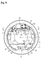
- a conventional LT type drum brake device as shown in Figures 8 and 9 has a pair of brake shoes 20, 30 mounted on a back plate 10 and elastically retained by shoe holding mechanisms 11, 11.
- the braking force generated by the conventional LT type drum brake device depends on a brake drum inner radius, on an activating force applied to the brake shoes by the pressurized hydraulic cylinder 40, and on a brake factor.
- the brake factor is known as a non-dimensional number which varies in accordance with a distance H 1 from a horizontal line passing through a brake center O between the brake shoes 20, 30 to the supporting point P of the respective brake shoes 20, 30 on the anchor device 13 as shown in Figure 8.
- a strut 50 with an automatic shoe clearance adjustment mechanism extends between the brake shoes 20 and 30.
- the left end of the strut 50 engages a shoe web 21 of the brake shoe 20, and the right end of the strut 50 engages a shoe web 31 of the brake shoe 30.
- the structure of the strut 50 is briefly explained with reference to Figure 9.
- the strut 50 is a one-shot automatic shoe clearance adjustment device which comprises an adjustment plate 51, a bell crank lever 52, a pin 55 and two springs 53, 54.
- the adjustment plate 51 has a notched groove 51a at the left side, and an inner edge of the shoe web 21 abuts against the bottom of the notched groove 51a.
- Small teeth 51b are formed on an intermediate portion of the adjustment plate 51.
- the bell crank lever 52 is rotatably pivotally supported relative to the adjustment plate 51 by the pin 55 in the intermediate portion thereof and longitudinally movable along the surface of the adjustment plate 51.
- another arm 52c of the bell crank lever 52 with a cam surface is freely fit into a rectangular hole 32 formed on the shoe web 31 with a gap at the left side of the rectangular hole 32.
- a first spring 53 extends between the shoe web 21 and the adjustment plate 51, and a second spring 54 extends between the adjustment plate 51 and the pin 55.
- the first and the second springs 53, 54 are so designed that a mounting load of the first spring 53 is higher than that of the second spring 54.
- the adjustment plate 51 and the bell crank lever 52 move to the left together with the brake shoe 20 due to the spring force of the springs 53, 54.
- the bell crank lever 52 rotates counterclockwise, as shown in Figure 9, for one pitch of the teeth to automatically adjust the clearance between the brake drum and the linings 23, 33, thereby maintaining the clearance to be always constant.
- the above-described conventional drum brake device has the following points to be improved:
- a braking force actually acts at the time when the brake shoes 20, 30 frictionally contact with the inner circumferential surface of the brake drum.
- the time from the beginning of the brake shoe opening to the contact of the linings thereof with the brake drum is said to be the "delay".
- the braking force increases in relation to the pressure supplied to the hydraulic cylinder 40, in case of a gentle incline of the braking force increase, the response time before the driver actually feels a braking action or deceleration is even longer, thus giving the vehicle driver an impression of an even longer delay in braking effectiveness and thus an insecure feeling.
- wetness on the frictional surfaces of the linings 23, 33 and the brake drum causes an over-braking effect compared to the braking effect under a normal condition. This may also make a vehicle stop with a jerk or a series of jerks, which may lead to a dangerous situation by making a driver to hit his/her face on the steering wheel or by moving freight or loose items inside the vehicle.
- the object of this invention is to provide a brake shoe anchor device for an internal drum brake device which resolves the problems mentioned above. More specifically, this invention aims at providing a brake shoe anchor device suitable to be employed in a drum brake device which eliminates the problem of the delay in the braking effectiveness or over-braking and which gives the driver a more secure feeling.
- a brake shoe anchor device for an internal drum brake device as defined in claim 1.
- Preferred embodiments of the invention are defined in the sub-claims.
- Embodiment 1 of this invention is explained with reference to Figures 1-5. Except for a brake shoe anchor device 60, this invention employs the same or a similar fundamental structure used in the above-described conventional drum brake device. Therefore, the same reference numbers as labeled above are used for the same or similar parts, and the explanation of the same is omitted.
- a conventional anchor device has one abutting point with each of the lower adjacent ends of the shoe webs 21, 31.
- this invention has two kinds of anchor members located at diametrical different positions, which alters the supporting points for each lower adjacent end 21a, 31a of the shoe webs 21, 31.
- This embodiment gives an example where a deformable anchor member is arranged closer to a brake center O of the drum brake, and a rigid anchor member is arranged farther from the brake center O than the deformable anchor member. The following is a more detailed explanation of this embodiment.
- a rectangular receiving plate 61 and a guiding plate 62 are superposed on a protrusion 10a of a back plate 10 and are fixed on the back plate 10 by means of rivets 63, 63, welding, or any other suitable fixing means or measure. Both ends of the guiding plate 62 overlap the shoe webs 21, 31 so as to prevent the lower adjacent ends 21a, 31a of the shoe webs 21, 31 from lifting upward.
- Projections 61a, 61a protrude on each side of the rectangular receiving plate 61 toward the shoe webs 21, 31 and are located closer to the brake center O than supporting surfaces 61b, 61b on each side of the receiving plate 61 as seen in the top view of Figure 1.
- Abutment grooves 21b, 31b are formed at the lower ends of the shoe webs 21, 31 directly facing these projections 61a, 61a.
- An elastic member 64 for example a coil spring having one side coiled over the projection 61a, is compressed between the bottom of the abutment groove 21b and one side surface of the receiving plate 61 (so as to be flush with the supporting surface 61b in this embodiment).
- another elastic member 64 for example a coil spring, too
- the spring force (spring constant/resiliency) of the elastic members 64, 64 is selected so that the resulting force is larger than that of the lower shoe return spring 12b such that slight clearances ⁇ 1 , ⁇ 1 are present between the adjacent lower ends 21a, 31a of the shoe webs 21, 31 and the supporting surfaces 61b, 61b of the rectangular receiving plate 61, respectively.
- each elastic member 64 functions as a deformable anchor member to resiliently or elastically support the adjacent lower ends 21a, 31a of the shoe webs 21, 31 of the brake shoes 20, 30 until a braking force reaches a predetermined value.
- each elastic member 64 no longer resiliently or elastically supports the lower ends 21a, 31a of the shoe web 21, 31 and thus changes the deformable anchor mechanism to a rigid anchor mechanism which rigidly supports the adjacent lower ends 21a, 31a of the shoe webs 21, 31 of the brake shoes 20, 30.
- the anchor device 60 is laterally mirror symmetrical as stated above and as shown in the Figures, the following sections only deal with the left half of the anchor device 60 and an explanation of the function of the right half of the anchor device supporting the brake shoe 30 is omitted.
- Figure 4 shows the anchor device 60 before the braking force reaches the predetermined value, wherein the lower end 21a of the brake shoe 20 is supported by the deformable/resilient anchor member comprising the elastic member 64 and there is a clearance ⁇ 1 between two facing surfaces thereof, i.e. between the lower end 21a of the brake shoe web 21 and the supporting surface 61b of the rectangular receiving plate 61.
- the brake shoe 20 continues to open with the abutting point between the lower end 21a of the shoe web 21 and the supporting surface 61b of the rectangular receiving plate 61 as the fulcrum, thereby braking the brake drum rotation.
- the lower end 21a of the shoe web 21 is supported at the deformable anchor member at the upper side of the rectangular receiving plate 61 (which is radially closer to the brake center O than the supporting point at the rigid anchor member) and is supported by the rigid anchor member at the lower side of the rectangular receiving plate 61 (which is radially farther from the brake center O than that at the deformable anchor member) when the braking force exceeds the predetermined value or magnitude.
- a distance H 2 from a horizontal line passing through the brake center O and extending essentially orthogonal to a line being a symmetrical line for the pair of brake shoes to a position where an elastic resilient member 64, i.e. the deformable anchor member, supports the adjacent lower ends 21a, 31a of the shoe webs 21, 31 of the brake shoes 20, 30, is designed to be shorter than a distance H 3 from this horizontal line passing through the brake center O to the supporting point between the adjacent lower ends 21a, 3la of the shoe webs 21, 31 of the brake shoes 20, 30 and the rigid anchor member of the rectangular receiving plate 61.
- the braking force achieved at the brake drum inner circumferential surface increases as the distance from the horizontal line passing through the brake center O to the anchor position where the brake shoes 20, 30 are supported becomes shorter. Therefore, at an early or initial stage of the braking operation, a larger braking force within a short period of time is attained by respectively supporting the adjacent lower ends 21a, 31a of the brake shoes 20, 30 by the elastic members 64, 64, i.e. by the deformable anchor member. This also eliminates the feeling of delay in braking effectiveness at the initial braking stage. Further, if the supporting points of the lower ends 21a, 31a of the brake shoes 20, 30 are changed from the deformable anchor member to the rigid anchor member, the drum brake device regains its usual braking effectiveness.
- Embodiment 2 of this invention is now explained below where the same reference numbers as labeled in the above Embodiment 1 are used for the same or similar parts and the explanation of the same is omitted.
- Figure 6 shows such other embodiment employing a plate spring as an elastic member 164 and an anchor member with inclined surfaces instead of an anchor with parallel surfaces as employed in Embodiment 1. While a right half of the anchor device 60 is not depicted in Figure 6, a supporting structure of the brake shoe 30 is mirror symmetrical to the structure at the left half of the anchor device 60 supporting the brake shoe 20.
- a plate spring is employed as the elastic member 164.
- the plate spring is formed by bending a strip material into an approximately C-shape adapted to be clipped to a lower end portion 21a of the shoe web 21.
- Hooks 164a, 164a are formed at both ends of the elastic member 164 so as to elastically fit into shallow grooves 21c, 21c located on radially inner and outer circumferential edges of the shoe web 21.
- a top section of a spring portion 164b is arched between the hooks 164a and 164a and abuts against the abutment surface 61b of the receiving plate 61.
- An approximately half portion of the edge surface of the lower end 21a of the shoe web 21 located closer to the brake center O is recessed to form a pocket for an upper end curve of the spring portion 164b of the elastic member 164 so as to allow the same to deform elastically at this section.
- This structure providing the supporting point between the elastically deformable spring portion and the rigid receiving plate 61 functions as the deformable or resilient anchor member where the spring portion 164b elastically abuts against but is supported by the plate 61 until the braking force reaches a predetermined value.
- the brake shoe 20 is opened with a supporting point located at the deformable anchor member comprising the elastically deformable or resilient spring portion 164b of the elastic member 164 at the early or initial braking stage and with a supporting point at the rigid anchor member thereafter.
- Figure 7 shows another embodiment of the invention which is a variation of Embodiments 1 and 2 where a deformable anchor member and a rigid anchor member are arranged upside down as compared to these previous embodiments.
- a deformable anchor member is formed with an elastic member 264 arranged between an edge surface of a lower end 21a of a shoe web 21 facing the anchor device at a radially farther from a brake center O and a supporting surface 61b of a receiving plate 61 while a rigid anchor member is formed with a clearance ⁇ 3 between the edge surface of the lower end 21a of the shoe web 21 at its radially closer to the brake center O and the supporting surface 61b of the receiving plate 61.
- a distance H 2 from a horizontal line passing through the brake center O, not shown in Figure 7, to the supporting point between the lower end 21a of the shoe web 21 and the elastic member 264 as the deformable anchor member is longer than a distance H 3 from the horizontal line to a supporting point between the lower end 21a of the shoe web 21 and the abutment surface 61b as the rigid anchor member. Accordingly, a braking force is lowered at the early or initial braking stage as compared to the previous embodiments.
- this Embodiment 3 has its advantage in preventing the over-braking phenomenon when frictional surfaces of linings and of a brake drum are wet, thereby eliminating the problem that a vehicle stops with jerks.
- the above described invention shall not be limited in application to the LT type drum brake device but it is applicable to the 2L type and a single shoe type internal shoe drum brake device which is configured with a hydraulic cylinder with a built-in single piston and a single brake shoe.
- a supporting surface of the anchor device in the invention has a broad range of applicability in that it may be utilized in a pivot anchor besides the above-described parallel or square slide anchor.
- the invention has the following advantages:
- a braking force at the early or initial braking stage is altered simply by providing a resilient or deformable anchor member and a rigid anchor member and by changing a supporting point of the shoe webs from one to the other at different radial positions.
- the design of this structure can be appropriately chosen by determining the locations of these anchor members and by considering characteristics of a variety of linings and design dimensions for different types of vehicles, thereby facilitating the design of an optimum drum brake device in a vehicle braking system.
Landscapes
- Engineering & Computer Science (AREA)
- General Engineering & Computer Science (AREA)
- Mechanical Engineering (AREA)
- Braking Arrangements (AREA)
Abstract
Description
Claims (5)
- A brake shoe anchor device for supporting an end of a brake shoe in an internal drum brake device, comprising:two anchor members located at radial different positions with respect to a center of the brake device, one is a rigid anchor member having a rigid anchor surface for rigidly supporting said end of the brake shoe and the other is a deformable/resilient anchor member having a deformable anchor surface for resiliently supporting said end of the brake shoe, whereinsaid two anchor members are arranged such that the brake shoe is supported by said deformable anchor member before a braking force reaches a predetermined value, and such thatsaid brake shoe is supported by said rigid anchor member when the braking force exceeds the predetermined value.
- A brake shoe anchor device as claimed in claim 1, wherein said deformable anchor member is positioned radially closer to a brake center than said rigid anchor member.
- A brake shoe anchor device as claimed in claim 1, wherein said deformable anchor member is positioned radially farther from a brake center than said rigid anchor member.
- A brake shoe anchor device as claimed in any one of claims 1 to 3, wherein said deformable anchor member is comprised of an elastic material.
- A brake shoe anchor device as claimed in any one of claims 1 to 3, wherein said deformable anchor member comprises a coil spring.
Applications Claiming Priority (2)
| Application Number | Priority Date | Filing Date | Title |
|---|---|---|---|
| JP11137383A JP2000329170A (en) | 1999-05-18 | 1999-05-18 | Brake shoe anchor device |
| JP13738399 | 1999-05-18 |
Publications (2)
| Publication Number | Publication Date |
|---|---|
| EP1054179A2 true EP1054179A2 (en) | 2000-11-22 |
| EP1054179A3 EP1054179A3 (en) | 2003-03-26 |
Family
ID=15197414
Family Applications (1)
| Application Number | Title | Priority Date | Filing Date |
|---|---|---|---|
| EP00110508A Withdrawn EP1054179A3 (en) | 1999-05-18 | 2000-05-17 | A brake shoe anchor device for an internal drum brake device |
Country Status (4)
| Country | Link |
|---|---|
| US (1) | US6345708B1 (en) |
| EP (1) | EP1054179A3 (en) |
| JP (1) | JP2000329170A (en) |
| KR (1) | KR20000077220A (en) |
Cited By (1)
| Publication number | Priority date | Publication date | Assignee | Title |
|---|---|---|---|---|
| US9915309B2 (en) | 2013-12-06 | 2018-03-13 | Continental Teves Ag & Co. Ohg | Drum brake module which can be operated by electric motor |
Families Citing this family (6)
| Publication number | Priority date | Publication date | Assignee | Title |
|---|---|---|---|---|
| US6681902B1 (en) * | 2002-06-04 | 2004-01-27 | Kelsey-Hayes Company | Brake shoe mounting system for a vehicle brake assembly |
| US20070265079A1 (en) * | 2006-05-09 | 2007-11-15 | Alvin Yu | TCS brake control system |
| DE102015112715A1 (en) * | 2015-08-03 | 2017-02-09 | Saf-Holland Gmbh | bearing element |
| KR101808141B1 (en) * | 2016-02-19 | 2017-12-12 | 주식회사 만도 | Drum brake |
| US12352325B2 (en) * | 2022-07-07 | 2025-07-08 | ZF Active Safety US Inc. | Drum brake assembly |
| DE102022208728B3 (en) * | 2022-08-23 | 2023-10-05 | Vitesco Technologies GmbH | Drum brake, braking system and vehicle |
Family Cites Families (10)
| Publication number | Priority date | Publication date | Assignee | Title |
|---|---|---|---|---|
| US3283858A (en) * | 1965-01-07 | 1966-11-08 | Bendix Corp | Brake |
| DE2364822C3 (en) * | 1973-12-28 | 1983-04-07 | Hahn Fahrzeugbau Gmbh, 7012 Fellbach | Inner shoe brake for an overrun brake device for trailers |
| JPS54124162A (en) * | 1978-03-20 | 1979-09-26 | Fuji Heavy Ind Ltd | Drum brake screaming preventive device |
| US4249646A (en) * | 1979-02-21 | 1981-02-10 | The Bendix Corporation | Drum brake assembly with non-servo and duo-servo characteristics |
| US4936426A (en) * | 1980-07-21 | 1990-06-26 | Dana Corporation | Brake assembly |
| DE3143683C2 (en) * | 1980-12-22 | 1986-03-20 | VEB Fahrzeugwerk Olbernhau, DDR 9330 Olbernhau | Support device for internal shoe brakes with automatic reversing for trailers with overrun brakes |
| GB8817007D0 (en) * | 1988-07-16 | 1988-08-17 | Bba Group Plc | Drum brake assembly |
| US5062506A (en) * | 1990-08-08 | 1991-11-05 | Eaton Corporation | Rotary drum brake assembly bracket |
| EP0629534A3 (en) * | 1993-06-16 | 1995-03-15 | Gerhard Spaegele | Mechanical release device. |
| JP3341147B2 (en) * | 1997-10-13 | 2002-11-05 | 日清紡績株式会社 | Drum brake device |
-
1999
- 1999-05-18 JP JP11137383A patent/JP2000329170A/en active Pending
-
2000
- 2000-05-10 KR KR1020000024977A patent/KR20000077220A/en not_active Withdrawn
- 2000-05-17 EP EP00110508A patent/EP1054179A3/en not_active Withdrawn
- 2000-05-17 US US09/572,085 patent/US6345708B1/en not_active Expired - Fee Related
Non-Patent Citations (1)
| Title |
|---|
| None |
Cited By (1)
| Publication number | Priority date | Publication date | Assignee | Title |
|---|---|---|---|---|
| US9915309B2 (en) | 2013-12-06 | 2018-03-13 | Continental Teves Ag & Co. Ohg | Drum brake module which can be operated by electric motor |
Also Published As
| Publication number | Publication date |
|---|---|
| EP1054179A3 (en) | 2003-03-26 |
| JP2000329170A (en) | 2000-11-28 |
| US6345708B1 (en) | 2002-02-12 |
| KR20000077220A (en) | 2000-12-26 |
Similar Documents
| Publication | Publication Date | Title |
|---|---|---|
| EP0388057B1 (en) | Automatic adjuster for drum brake | |
| EP1054179A2 (en) | A brake shoe anchor device for an internal drum brake device | |
| US5630486A (en) | Mechanical actuation device for drum brake | |
| JP2004360761A (en) | Drum brake device | |
| EP1193417A2 (en) | Drum brake device having a shoe clearance over-adjustment prevention apparatus | |
| US6302245B1 (en) | Drum brake device | |
| US4502573A (en) | Automatic-adjustment drum brake | |
| JPS5865337A (en) | Disk brake | |
| JP5457723B2 (en) | Drum brake device with automatic shoe clearance adjustment device | |
| WO2008079087A1 (en) | Method and device for disc brakes and vehicle | |
| JPH0239646B2 (en) | JIDOCHOSEISOCHITSUKIDORAMUBUREEKI | |
| US4051928A (en) | Automatic shoe clearance adjusting device in shoe drum brake | |
| US2554291A (en) | Brake actuating mechanism | |
| US6554110B2 (en) | Drum brake device | |
| JPH0130668Y2 (en) | ||
| US6547047B2 (en) | Drum brake device | |
| JPH0147660B2 (en) | ||
| JPS628439Y2 (en) | ||
| JPS58174735A (en) | Automatic shoe gap adjusting device for brake | |
| JP3774036B2 (en) | Duo servo drum brake | |
| JP2001020979A (en) | Drum brake device | |
| JPH0124443Y2 (en) | ||
| JPS5833312Y2 (en) | Automatic gap adjustment device for drum brake equipment | |
| JP4049261B2 (en) | Automatic brake shoe clearance adjustment device for drum brakes | |
| JPS5814254Y2 (en) | Automatic gap adjustment device for drum brake equipment |
Legal Events
| Date | Code | Title | Description |
|---|---|---|---|
| PUAI | Public reference made under article 153(3) epc to a published international application that has entered the european phase |
Free format text: ORIGINAL CODE: 0009012 |
|
| AK | Designated contracting states |
Kind code of ref document: A2 Designated state(s): AT BE CH CY DE DK ES FI FR GB GR IE IT LI LU MC NL PT SE |
|
| AX | Request for extension of the european patent |
Free format text: AL;LT;LV;MK;RO;SI |
|
| PUAL | Search report despatched |
Free format text: ORIGINAL CODE: 0009013 |
|
| AK | Designated contracting states |
Kind code of ref document: A3 Designated state(s): AT BE CH CY DE DK ES FI FR GB GR IE IT LI LU MC NL PT SE Designated state(s): AT BE CH CY DE DK ES FI FR GB GR IE IT LI LU MC NL PT SE |
|
| AX | Request for extension of the european patent |
Extension state: AL LT LV MK RO SI |
|
| AKX | Designation fees paid | ||
| REG | Reference to a national code |
Ref country code: DE Ref legal event code: 8566 |
|
| STAA | Information on the status of an ep patent application or granted ep patent |
Free format text: STATUS: THE APPLICATION IS DEEMED TO BE WITHDRAWN |
|
| 18D | Application deemed to be withdrawn |
Effective date: 20031201 |