EP1054176A2 - Drain mechanism for hydraulic power transmission joint - Google Patents
Drain mechanism for hydraulic power transmission joint Download PDFInfo
- Publication number
- EP1054176A2 EP1054176A2 EP00109514A EP00109514A EP1054176A2 EP 1054176 A2 EP1054176 A2 EP 1054176A2 EP 00109514 A EP00109514 A EP 00109514A EP 00109514 A EP00109514 A EP 00109514A EP 1054176 A2 EP1054176 A2 EP 1054176A2
- Authority
- EP
- European Patent Office
- Prior art keywords
- drain
- pin
- thermo
- switch
- valve block
- Prior art date
- Legal status (The legal status is an assumption and is not a legal conclusion. Google has not performed a legal analysis and makes no representation as to the accuracy of the status listed.)
- Granted
Links
- 230000007246 mechanism Effects 0.000 title claims description 25
- 230000005540 biological transmission Effects 0.000 title claims description 16
- 238000006243 chemical reaction Methods 0.000 claims abstract description 5
- 238000006073 displacement reaction Methods 0.000 abstract description 4
- 239000003921 oil Substances 0.000 description 18
- 230000004308 accommodation Effects 0.000 description 7
- 230000000903 blocking effect Effects 0.000 description 2
- 230000002265 prevention Effects 0.000 description 2
- 230000008602 contraction Effects 0.000 description 1
- 230000008878 coupling Effects 0.000 description 1
- 238000010168 coupling process Methods 0.000 description 1
- 238000005859 coupling reaction Methods 0.000 description 1
- 239000012208 gear oil Substances 0.000 description 1
- 230000006872 improvement Effects 0.000 description 1
- 239000000314 lubricant Substances 0.000 description 1
- 239000002245 particle Substances 0.000 description 1
- 230000009467 reduction Effects 0.000 description 1
- 230000000717 retained effect Effects 0.000 description 1
- 238000005549 size reduction Methods 0.000 description 1
Images


Classifications
-
- F—MECHANICAL ENGINEERING; LIGHTING; HEATING; WEAPONS; BLASTING
- F16—ENGINEERING ELEMENTS AND UNITS; GENERAL MEASURES FOR PRODUCING AND MAINTAINING EFFECTIVE FUNCTIONING OF MACHINES OR INSTALLATIONS; THERMAL INSULATION IN GENERAL
- F16D—COUPLINGS FOR TRANSMITTING ROTATION; CLUTCHES; BRAKES
- F16D43/00—Automatic clutches
- F16D43/28—Automatic clutches actuated by fluid pressure
- F16D43/284—Automatic clutches actuated by fluid pressure controlled by angular speed
-
- F—MECHANICAL ENGINEERING; LIGHTING; HEATING; WEAPONS; BLASTING
- F16—ENGINEERING ELEMENTS AND UNITS; GENERAL MEASURES FOR PRODUCING AND MAINTAINING EFFECTIVE FUNCTIONING OF MACHINES OR INSTALLATIONS; THERMAL INSULATION IN GENERAL
- F16D—COUPLINGS FOR TRANSMITTING ROTATION; CLUTCHES; BRAKES
- F16D31/00—Fluid couplings or clutches with pumping sets of the volumetric type, i.e. in the case of liquid passing a predetermined volume per revolution
- F16D31/02—Fluid couplings or clutches with pumping sets of the volumetric type, i.e. in the case of liquid passing a predetermined volume per revolution using pumps with pistons or plungers working in cylinders
Definitions
- the present invention relates generally to a drain mechanism for a hydraulic power transmission joint for use in 4 wheel-drive mechanisms for motor vehicles, and more particularly to a drain mechanism for a hydraulic power transmission joint for switching from 4 wheel-drive to 2 wheel-drive depending on a rise in temperature.
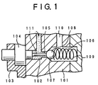
- FIGs. 1 to 3 illustrate an exemplary drain mechanism for a hydraulic power transmission joint being currently developed by the present inventors on the basis of such United State Patents.
- This drain mechanism serves to perform a drainage from a high-pressure chamber to a low-pressure chamber when the temperature of oil has reached a predetermined level, to substantially nullify the transmission torque for the switching to 2 wheel-drive.
- a valve block 101 is coupled to a rotor not shown, for integral rotations with the rotor.
- the rotor is spline coupled to a main shaft directly connecting with rear wheels, for integral rotations with the main shaft.
- the valve block 101 is formed with a high-pressure chamber 102 that communicates with a discharge hole formed in the rotor.
- the valve block 101 is formed with an orifice not shown that leads to the high-pressure chamber 102.
- a thermo-switch 104 is screwed by a securing member to the end face of the valve block 101 in such a manner that the thermo-switch 104 is inserted into the high-pressure chamber 102.
- the valve block 101 is provided with a drain hole 105 that opens to the high-pressure chamber 102.
- the valve block 101 is further provided with an accommodation hole 106 that communicates via a drain hole 105 to the high-pressure chamber 102.
- a check ball 108 for blocking the drain hole 105 is seated on a valve seat 107 formed in the accommodation hole 106.
- the check ball 108 is urged by a return spring 109.
- the valve block 101 is formed with a drain passage 110 that leads to the accommodation hole 106.
- the thermo-switch 104 has a head pin 111 adapted to be inserted into the drain hole 105 so as to press the check ball to open the drain hole 105.
- thermo-switch 104 when a predetermined temperature is reached, causes the head pin 111 to extend to press the check ball 108 to open the drain hole 105, as shown in FIG. 2, allowing oil to be drained through the drain passage 110 into the low-pressure chamber to thereby substantially nullify the transmission torque for the switching to 2 wheel-drive.
- the check ball 108 when the temperature at the thermo-switch 104 falls below the predetermined level, the check ball 108 is pushed back by the biasing force of the return spring 109, allowing the head pin 111 to return to its original position to block the drain hole 105. The drainage of oil is thus ceased, allowing a return to 4 wheel-drive based on the torque transmission.
- FIG. 3 depicts another drain mechanism.
- a valve body 112 is integrally formed with the fore-end of the head pin 111 of the thermo-switch fixedly secured to the valve block 101.
- the valve body is urged by the return spring 109 to block the drain hole 105.
- the head pin 111 is extended rightward so that the valve body 112 is displaced rightward against the return spring 109, to thereby open the drain hole 105.
- Oil flows from the high-pressure chamber 102 through the drain hole 105 into the accommodation hole 106 that accommodates the return spring 109, after which it is drained through the drain passage 110 into the low-pressure chamber.
- the return spring 109 biases the valve body 112 to block the drain hole, thus ceasing the drainage of oil.
- thermo-switch tends to have a low strength-related durability since it is housed in the high-pressure chamber.
- the diameter of the drain hole needs to be increased in order to allow for the passage of the head pin therethrough, thus subjecting the check ball to a larger load.
- the check ball has a larger pressure receive area, it may be possible to deal with the high pressure by adding to the biasing force of the return spring, although another problem still remains that it may be difficult to raise the pressure to a higher level since the biasing force acquired by the return spring is limitative.
- the present invention provides a drain mechanism for a hydraulic power transmission joint ensuring an improved strength and durability of a thermo-switch and achieving a high-pressure setting by a return spring, as well as a reduction in size.
- a drain mechanism for a hydraulic power transmission joint adapted to be interposed between an input shaft and an output shaft that are rotatable relative to each other, to transmit torque as a function of the rotational-speed difference between the input and output shafts
- the drain mechanism comprising a drain plug accommodated within a valve block and having a drain hole through which oil is introduced from a high-pressure chamber; a thermo-switch located within a low-pressure chamber in the valve block in such a manner as to be urged by a return spring, the thermo-switch having a head pin that protrudes when a predetermined temperature is reached; a fixed pin fixedly inserted into the valve block, the fixed pin being positioned so as to allow a head pin of the thermo-switch urged by the return spring to abut thereagainst, the fixed pin when the head pin protrudes at the predetermined temperature causing the thermo-switch to retreat against the return spring; and a drain pin slidably located within the drain
- the present invention allows the thermo-switch to be displaceably arranged in the low-pressure chamber, so that no high pressure acts on the thermo-switch, which contributes to an improvement in the strength and durability. Furthermore, there is no need to insert the head pin of the thermo-switch into the drain hole, with the result that the diameter of the drain hole can be reduced, enabling the hydraulic pressure at the high pressure side to be set at a higher level. In addition, there is no need for specific members for fixing the thermo-switch, making it possible to achieve a miniaturization while keeping the same performances.
- the drain pin may have a recessed portion which is formed at its rear end side and which is open rearward, the recessed portion receiving the fixed pin that extends therethrough, with the head pin of the thermo-switch being inserted into the recessed portion so as to allow the head pin to abut against the fixed pin. This contributes to a secure restriction of the displacement of the drain pin, as well as to a secure operation of the thermo-switch.
- the hydraulic power transmission joint employing the drain mechanism of the present invention comprises a housing coupled to the input shaft and having a cam face formed on its inner side surface; a rotor coupled to the output shaft and being rotatably accommodated in the housing, the rotor having a plurality of axially extending plunger chambers; a plurality of plungers each being reciprocatively accommodated in each of the plurality of plungers under a biasing force of the return spring, the plurality of plungers being operated by the cam face upon the relative rotations of the input and output shafts; and a discharge hole formed in the rotor and opening to the plurality of plunger chambers; wherein the valve block is coupled to the rotor so that oil discharged by the operation of the plungers induces a reaction force in the plungers due to a flow resistance upon the passage through an orifice provided in the valve block, to thereby transmit torque between the housing and the rotor.
- FIG. 4 is a sectional view of a hydraulic power transmission joint employing a drain mechanism in accordance with the present invention.
- a companion flange 1 is coupled to a propeller shaft not shown acting as a front wheel driving shaft.
- a cam housing shank 2 is inserted into the companion flange 1 for spline coupling.
- the cam housing shank 2 has on its outer periphery a front bearing 3 by way of which the cam housing shank 2 is supported on a differential gear case 4.
- a seal member 5 and a cover 6 that prevent in cooperation entrance of foreign particles and outflow of differential gear oil.
- a housing 8 is secured at a weld 7 to the right-hand end of the cam housing shank 2.
- the cam housing shank 2 On its inner side surface, the cam housing shank 2 is provided with a cam face 9 having two or more raised portions. Plugs 10 and 11 are inserted into the cam housing shank 2, for allowing oil to be injected into the interior of the joint or discharged therefrom.
- a rotor 12 is rotatably accommodated in the housing 8 and is engaged with a main shaft 13 for integral rotation therewith.
- a drive pinion gear 14 of a rear differential gear is fixedly inserted into the interior of the main shaft 13 from right side so that the main shaft 13 rotates jointly with the drive pinion gear 14.
- the rotor 12 is formed with a plurality of axially extending plunger chambers 15, each of which houses a plunger 16 slidably by way of a return spring 17.
- An intake passage 18 is formed in the plunger 16 at its head side that communicates with a low-pressure chamber 19.
- the intake passage 18 opens to the plunger chamber 15 by way of a communication hole 20 that is opened or closed by a one-way valve block 21 for intake in the form of a ball.
- the interior of the plunger chamber 15 is formed with a valve seat 22 on which the one-way valve block 21 is seated.
- a check plug 23 is disposed at the stepped portion of the valve seat 22. Between the check plug 23 and the one-way valve block 21 there is interposed a check spring not shown that serves to urge the one-way valve block 21 for positioning.
- the return spring 17 intervenes between the check plug 23 and the bottom of the rotor 12.
- a discharge hole 24 is formed in the rotor 12 so as to open to the plunger chamber 15.
- a one-way valve block 25 for discharge in the form of a ball is disposed in the discharge hole 24.
- the discharge hole 24 is formed with a valve seat 26 on which the one-way valve block 25 is seated.
- the rotor 12 is followed by a valve block 27 which is provided with a high-pressure chamber 28 that communicates with the discharge hole 24 of the rotor 12.
- a restriction member 29 projects into the high-pressure chamber 28 for positioning the one-way valve block 25 at a predetermined location.
- the valve block 27 is provided with an orifice member 31 having an orifice 30 that leads to the high-pressure chamber 28.
- the valve block 27 and the rotor 12 are positioned relative to each other by a pin 32 and are rigidly fastened together by a bolt 33.
- the one-way valve 25 for discharge at the discharge hole 24 of the rotor 12 is closed blocking a back flow of oil from the high-pressure chamber 28.
- the one-way valve block 25 at discharge side is opened allowing oil within the plunger chamber 15 to flow through the discharge hole 24 and high-pressure chamber 28 into the orifice 30.
- the one-way valve 21 for intake is closed to prevent oil from leaking through the communication hole 20 and intake passage 18 into the low-pressure chamber 19.
- the valve block 27 is followed by a bearing retainer 34.
- the bearing retainer 34 is rigidly press fitted into the housing 8 and is positioned by a snap ring 35.
- the bearing retainer 34 is formed with a through-hole 36 that communicates with the low-pressure chamber 19. Needle bearings 37 and 38 are interposed between the bearing retainer 34 and the valve block 27 and between the bearing retainer 34 and the main shaft 13, respectively.
- An oil seal 39 is also provided between the bearing retainer 34 and the main shaft 13 for the prevention of an outflow of oil.
- an accumulator piston 40 for absorbing oil thermal expansion and contraction, the accumulator piston 40 defining an accumulator chamber 41 that communicates with the low-pressure chamber 19 by way of the through-hole 36 in the bearing retainer 34.
- O-rings 42 and 43 are interposed between the accumulator piston 40 and the housing 8 and between the accumulator piston 40 and the bearing retainer 34, respectively.
- Return springs 45 and 46 are disposed between an accumulator retainer 44 and the bottom of the accumulator piston 40.
- the extended portion of the bearing retainer 34 has on its outer periphery a rear bearing 47 by way of which the bearing retainer 34 is supported by the differential gear case 4.
- a lubricant groove 48 and a seal member 49 are provided in the left-hand opening of the main shaft 13.
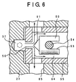
- FIGs. 5A and 5B are sectional views of an embodiment of a drain mechanism in accordance with the present invention, with FIG. 5A depicting the pre-operation status, and FIG. 5B depicting the post-operation status.
- the valve block 27 is coupled to the rotor 12 and rotates jointly with the rotor 12.
- the valve block 27 includes an accommodation hole 50 that is formed with a threaded portion 51 for receiving a switch plug 52.
- the valve block 27 is formed with a bearing seat 53 for the needle bearing 37.
- a fixed pin 54 is inserted from the bearing seat 53 through the accommodation hole 50 and is retained rigidly by the needle bearing 37 for the prevention of dislocation.
- a metallic seal washer 72 is first placed on the bottom at the left-hand end of the accommodation hole 50 and then a drain plug 55 is inserted and is fixed by the switch plug 52.
- the drain plug 55 is of a substantially cup-shaped profile that opens rearward (rightward).
- the end face of the drain plug 55 is formed with a drain hole 56 that communicates with the high-pressure side.
- the valve block 27 is formed with a high-pressure port 57 which opens to the drain hole 56 and which leads through a high-pressure passage 58 to a high-pressure chamber 59.
- a drain pin 60 is received in the drain plug 55 so as to be able to open and close the drain hole 56, the drain pin 60 having at its fore-end a protrusion 61 for opening and closing the drain hole 56.
- the protrusion 61 is in the shape of a cone having a substantially triangular profile, with the tapered face of the protrusion 61 abutting against the opening end of the drain hole 56.
- the drain hole 56 can thus be blocked by the protrusion 61 even though the drain hole 56 has a smaller diameter.
- the drain pin 60 is open at the opposed end to the protrusion 60 and is provided with an recessed portion 63 that opens rearward (rightward).
- the fixed pin 54 is inserted through the recessed portion 63 of the drain pin 60 in such a manner that when the drain pin 60 is displaced to open the drain hole 56, the recessed portion 63 is brought into abutment against the fixed pin 54 so that the displacement of the drain pin 60 is restricted.
- a drain passage 65 is provided in a drain chamber 64 of the drain plug 55 within which the drain pin 60 is received, allowing oil to flow from the high-pressure port 57 through the drain hole 56 into the drain passage 65 prior to drainage into a low-pressure chamber.
- a low-pressure chamber 66 which displaceably accommodates a thermo-switch 67 that has a shoulder 68 formed on its outer periphery.
- a return spring 70 is interposed between the shoulder 68 and the switch plug 52, and a return spring 69 is interposed between the bottom of the thermo-switch 67 and the switch plug 52.
- thermo-switch 67 is urged by the return springs 69 and 70 so as to press the drain pin 60 leftward to thereby block the drain hole 56.
- the thermo-switch 67 has a head pin 71 located centrally at its fore-end in such a manner that previous to the operation, a minute gap is formed between the head pin 71 and the fixed pin 54. Arrangement is such that when a predetermined temperature is reached, the head pin 71 is extended to abut against the fixed pin 54, with the resultant reaction force causing the thermo-switch 67 to retreat rightward against the return springs 69 and 70, whereupon a high-pressure from the high-pressure port 57 causes a rightward displacement of the drain pin 60 to open the drain hole 56.
- the thermo-switch 67 is accommodated in the low-pressure chamber 66 so as to press the drain pin 60 while being urged by the return springs 60 and 70, with no need for any members to fixing the thermo-switch 67.
- the drain pin 60 is urged leftward via the thermo-switch 67 by the return springs 69 and 70 so that its protrusion 61 blocks the drain hole 56.
- the head pin 71 of the thermo-switch 67 is urged by the return springs 69 and 70 to enter the recessed portion 63 formed in the drain pin 60 but is prevented from abutting against the fixed pin 54 with a minute gap therebetween.
- thermo-switch 67 When the temperature at the thermo-switch 67 rises up to a predetermined level, the head pin 71 of the thermo-switch 67 is extended leftward to abut against the fixed pin 54, with the resultant reaction force causing the thermo-switch 67 to retreat rightward as seen in FIG. 5B against the return springs 69 and 70. Once the thermo-switch 67 retreats rightward, the force pressing the drain pin 60 is cut off, releasing the drain pin 60, which in turn is displaced rightward by a high pressure from the high-pressure port 57 to open the drain hole 56. For this reason, oil within the high-pressure port 57 flows as indicated by an arrow through the drain hole 56 and then drain chamber 64 into the drain passage 65. That is, as seen in FIG.
- thermo-switch 67 is displaceably arranged within the low-pressure chamber 66 so as to prevent a high pressure from acting on the thermo-switch 67, so that its strength and durability can be improved.
- thermo-switch 67 there is no need to insert the head pin of the thermo-switch into the drain hole 56, with the result that the diameter of the drain hole 56 can be reduced allowing a hydraulic pressure at high pressure side to be set to a high level.
- thermo-switch 67 there is no need for any specific members for completely fixing the thermo-switch 67, whereby it is possible to achieve a size reduction while keeping the same performance.
Landscapes
- Engineering & Computer Science (AREA)
- General Engineering & Computer Science (AREA)
- Mechanical Engineering (AREA)
- Physics & Mathematics (AREA)
- Fluid Mechanics (AREA)
- Hydraulic Clutches, Magnetic Clutches, Fluid Clutches, And Fluid Joints (AREA)
- Control Of Transmission Device (AREA)
Abstract
Description
Claims (3)
- A drain mechanism for a hydraulic power transmission joint adapted to be interposed between an input shaft and an output shaft that are rotatable relative to each other, to transmit torque as a function of the rotational-speed difference between said input and output shafts, said drain mechanism comprising:a drain plug accommodated within a valve block and having a drain hole through which oil is introduced from a high-pressure chamber;a thermo-switch located within a low-pressure chamber in said valve block in such a manner as to be urged by a return spring, said thermo-switch having a head pin that protrudes when a predetermined temperature is reached;a fixed pin fixedly inserted into said valve block, said fixed pin being positioned so as to allow a head pin of said thermo-switch urged by said return spring to abut thereagainst, said fixed pin when said head pin protrudes at said predetermined temperature causing said thermo-switch to retreat against said return spring; anda drain pin slidably located within said drain plug, said drain pin being pressed by said thermo-switch to close said drain hole for the duration in which said predetermined temperature is not reached, said drain pin when said predetermined temperature is reached, opening said drain hole as a result of cutoff of the pressing force caused by a retreat of said thermo-switch.
- A drain mechanism according to claim 1, wherein said drain pin has a recessed portion which is formed at its rear end side and which is open rearward, said recessed portion receiving said fixed pin that extends therethrough, with said head pin of said thermo-switch being inserted into said recessed portion so as to allow said head pin to abut against said fixed pin.
- A drain mechanism according to claim 1, wherein said hydraulic power transmission joint comprising:a housing coupled to said input shaft and having a cam face formed on its inner side surface;a rotor coupled to said output shaft and being rotatably accommodated in said housing, said rotor having a plurality of axially extending plunger chambers;a plurality of plungers each being reciprocatively accommodated in each of said plurality of plungers under a biasing force of said return spring, said plurality of plungers being operated by said cam face upon the relative rotations of said input and output shafts; anda discharge hole formed in said rotor and opening to said plurality of plunger chambers; whereinsaid valve block is coupled to said rotor so that oil discharged by the operation of said plungers induces a reaction force in said plungers due to a flow resistance upon the passage through an orifice provided in said valve block, to thereby transmit torque between said housing and said rotor.
Applications Claiming Priority (2)
| Application Number | Priority Date | Filing Date | Title |
|---|---|---|---|
| JP13545099 | 1999-05-17 | ||
| JP13545099A JP3807585B2 (en) | 1999-05-17 | 1999-05-17 | Drain mechanism of hydraulic power transmission joint |
Publications (3)
| Publication Number | Publication Date |
|---|---|
| EP1054176A2 true EP1054176A2 (en) | 2000-11-22 |
| EP1054176A3 EP1054176A3 (en) | 2000-12-20 |
| EP1054176B1 EP1054176B1 (en) | 2004-07-28 |
Family
ID=15152007
Family Applications (1)
| Application Number | Title | Priority Date | Filing Date |
|---|---|---|---|
| EP00109514A Expired - Lifetime EP1054176B1 (en) | 1999-05-17 | 2000-05-04 | Drain mechanism for hydraulic power transmission joint |
Country Status (4)
| Country | Link |
|---|---|
| US (1) | US6336539B1 (en) |
| EP (1) | EP1054176B1 (en) |
| JP (1) | JP3807585B2 (en) |
| DE (1) | DE60012419T2 (en) |
Cited By (3)
| Publication number | Priority date | Publication date | Assignee | Title |
|---|---|---|---|---|
| US6336539B1 (en) | 1999-05-17 | 2002-01-08 | Fujiunivance Co. | Drain mechanism for hydraulic power transmission joint |
| US6422368B1 (en) * | 1999-05-28 | 2002-07-23 | Fujiunivance Co. | Hydraulic power transmission joint |
| US6454070B1 (en) * | 1999-05-17 | 2002-09-24 | Fujiunivance Co. | Drain mechanism for hydraulic power transmission joint |
Families Citing this family (2)
| Publication number | Priority date | Publication date | Assignee | Title |
|---|---|---|---|---|
| AT5220U1 (en) * | 2001-04-02 | 2002-04-25 | Steyr Powertrain Ag & Co Kg | SPEED DIFFERENTIAL-RELATED HYDRAULIC CLUTCH WITH CONTROL VALVE |
| KR101519254B1 (en) | 2013-12-09 | 2015-05-11 | 현대자동차주식회사 | Thermo bypass valve and method for detecting failure of thermo bypass valve |
Family Cites Families (9)
| Publication number | Priority date | Publication date | Assignee | Title |
|---|---|---|---|---|
| US4456110A (en) | 1980-10-11 | 1984-06-26 | Horton Industries, Inc. | Self-contained fan clutch |
| US5037353A (en) | 1989-01-17 | 1991-08-06 | Fuji Tekko Co., Ltd. | Hydraulic power transmission joint which is used in vehicles |
| US5103642A (en) | 1990-07-12 | 1992-04-14 | Fuji Tekko Co., Ltd. | Rotary shaft coupler with rotary valve plate position dependent on direction of shaft rotation |
| JPH0483920A (en) | 1990-07-24 | 1992-03-17 | Fuji Tool & Die Co Ltd | Hydraulic power transmission joint |
| US5595214A (en) * | 1993-02-10 | 1997-01-21 | Asha Corporation | Hydraulic coupling for vehicle drivetrain |
| US5706658A (en) * | 1995-01-17 | 1998-01-13 | Fuji Univance Corporation | Rotary shaft coupler with rotary valve plate position dependent on direction of shaft rotation |
| JP2000310246A (en) | 1999-04-23 | 2000-11-07 | Fuji Univance Corp | Hydraulic power transmission coupling |
| JP3807585B2 (en) | 1999-05-17 | 2006-08-09 | 株式会社ユニバンス | Drain mechanism of hydraulic power transmission joint |
| JP3807586B2 (en) | 1999-05-28 | 2006-08-09 | 株式会社ユニバンス | Hydraulic power transmission coupling |
-
1999
- 1999-05-17 JP JP13545099A patent/JP3807585B2/en not_active Expired - Lifetime
-
2000
- 2000-05-04 EP EP00109514A patent/EP1054176B1/en not_active Expired - Lifetime
- 2000-05-04 DE DE60012419T patent/DE60012419T2/en not_active Expired - Lifetime
- 2000-05-15 US US09/571,357 patent/US6336539B1/en not_active Expired - Lifetime
Cited By (3)
| Publication number | Priority date | Publication date | Assignee | Title |
|---|---|---|---|---|
| US6336539B1 (en) | 1999-05-17 | 2002-01-08 | Fujiunivance Co. | Drain mechanism for hydraulic power transmission joint |
| US6454070B1 (en) * | 1999-05-17 | 2002-09-24 | Fujiunivance Co. | Drain mechanism for hydraulic power transmission joint |
| US6422368B1 (en) * | 1999-05-28 | 2002-07-23 | Fujiunivance Co. | Hydraulic power transmission joint |
Also Published As
| Publication number | Publication date |
|---|---|
| DE60012419D1 (en) | 2004-09-02 |
| JP3807585B2 (en) | 2006-08-09 |
| EP1054176B1 (en) | 2004-07-28 |
| JP2000320576A (en) | 2000-11-24 |
| US6336539B1 (en) | 2002-01-08 |
| DE60012419T2 (en) | 2005-07-28 |
| EP1054176A3 (en) | 2000-12-20 |
Similar Documents
| Publication | Publication Date | Title |
|---|---|---|
| US7219496B2 (en) | Pressure-limiting device in a hydraulic path for clutch actuation | |
| US7568497B1 (en) | Combined check valve and pressure relief valve | |
| CN104412012A (en) | Adjustment device for actuating the parking lock | |
| EP1424517A2 (en) | Hydraulically actuated by-pass valve | |
| US7296594B1 (en) | Combination check valve and neutral valve assembly for use in a hydraulic component | |
| EP1054176B1 (en) | Drain mechanism for hydraulic power transmission joint | |
| US6719005B1 (en) | Combination check valve and pressure release valve | |
| US4296649A (en) | Hydraulically operated transmission control | |
| US6422368B1 (en) | Hydraulic power transmission joint | |
| EP1055837B1 (en) | Hydrostatic coupling | |
| KR0151500B1 (en) | Pneumatic rotary shaft coupler | |
| EP1054177B1 (en) | Drain valve for hydrostatic coupling | |
| US6964280B1 (en) | Valve assembly for use in a hydraulic component | |
| US7320334B1 (en) | Valve Assembly | |
| US6986363B1 (en) | Valve assembly for use in a hydraulic component | |
| US6293381B1 (en) | Hydraulic power transmission joint | |
| US6341682B1 (en) | Hydraulic power transmission joint | |
| US6257387B1 (en) | Hydraulic power transmission joint | |
| US6761182B1 (en) | Method for configuration of a valve | |
| JP2886816B2 (en) | Hydraulic power transmission coupling | |
| JP2989433B2 (en) | Hydraulic power transmission coupling | |
| JP2000310246A (en) | Hydraulic power transmission coupling | |
| JP4253792B2 (en) | Drain mechanism of hydraulic power transmission joint | |
| JP2886795B2 (en) | Hydraulic power transmission coupling | |
| JP3816757B2 (en) | Drain mechanism of hydraulic power transmission joint |
Legal Events
| Date | Code | Title | Description |
|---|---|---|---|
| PUAI | Public reference made under article 153(3) epc to a published international application that has entered the european phase |
Free format text: ORIGINAL CODE: 0009012 |
|
| PUAL | Search report despatched |
Free format text: ORIGINAL CODE: 0009013 |
|
| AK | Designated contracting states |
Kind code of ref document: A2 Designated state(s): DE FR GB |
|
| AX | Request for extension of the european patent |
Free format text: AL;LT;LV;MK;RO;SI |
|
| AK | Designated contracting states |
Kind code of ref document: A3 Designated state(s): AT BE CH CY DE DK ES FI FR GB GR IE IT LI LU MC NL PT SE |
|
| AX | Request for extension of the european patent |
Free format text: AL;LT;LV;MK;RO;SI |
|
| 17P | Request for examination filed |
Effective date: 20010111 |
|
| AKX | Designation fees paid |
Free format text: DE FR GB |
|
| 17Q | First examination report despatched |
Effective date: 20030930 |
|
| GRAP | Despatch of communication of intention to grant a patent |
Free format text: ORIGINAL CODE: EPIDOSNIGR1 |
|
| GRAS | Grant fee paid |
Free format text: ORIGINAL CODE: EPIDOSNIGR3 |
|
| GRAA | (expected) grant |
Free format text: ORIGINAL CODE: 0009210 |
|
| AK | Designated contracting states |
Kind code of ref document: B1 Designated state(s): DE FR GB |
|
| REG | Reference to a national code |
Ref country code: GB Ref legal event code: FG4D |
|
| REF | Corresponds to: |
Ref document number: 60012419 Country of ref document: DE Date of ref document: 20040902 Kind code of ref document: P |
|
| ET | Fr: translation filed | ||
| PLBE | No opposition filed within time limit |
Free format text: ORIGINAL CODE: 0009261 |
|
| STAA | Information on the status of an ep patent application or granted ep patent |
Free format text: STATUS: NO OPPOSITION FILED WITHIN TIME LIMIT |
|
| 26N | No opposition filed |
Effective date: 20050429 |
|
| REG | Reference to a national code |
Ref country code: FR Ref legal event code: PLFP Year of fee payment: 16 |
|
| REG | Reference to a national code |
Ref country code: FR Ref legal event code: PLFP Year of fee payment: 17 |
|
| REG | Reference to a national code |
Ref country code: FR Ref legal event code: PLFP Year of fee payment: 18 |
|
| REG | Reference to a national code |
Ref country code: FR Ref legal event code: PLFP Year of fee payment: 19 |
|
| PGFP | Annual fee paid to national office [announced via postgrant information from national office to epo] |
Ref country code: DE Payment date: 20180529 Year of fee payment: 19 |
|
| PGFP | Annual fee paid to national office [announced via postgrant information from national office to epo] |
Ref country code: FR Payment date: 20180523 Year of fee payment: 19 |
|
| PGFP | Annual fee paid to national office [announced via postgrant information from national office to epo] |
Ref country code: GB Payment date: 20180523 Year of fee payment: 19 |
|
| REG | Reference to a national code |
Ref country code: DE Ref legal event code: R119 Ref document number: 60012419 Country of ref document: DE |
|
| GBPC | Gb: european patent ceased through non-payment of renewal fee |
Effective date: 20190504 |
|
| PG25 | Lapsed in a contracting state [announced via postgrant information from national office to epo] |
Ref country code: GB Free format text: LAPSE BECAUSE OF NON-PAYMENT OF DUE FEES Effective date: 20190504 Ref country code: DE Free format text: LAPSE BECAUSE OF NON-PAYMENT OF DUE FEES Effective date: 20191203 |
|
| PG25 | Lapsed in a contracting state [announced via postgrant information from national office to epo] |
Ref country code: FR Free format text: LAPSE BECAUSE OF NON-PAYMENT OF DUE FEES Effective date: 20190531 |