EP1054161A1 - Control valve with mechanical feedback and method for controlling fluid flow - Google Patents
Control valve with mechanical feedback and method for controlling fluid flow Download PDFInfo
- Publication number
- EP1054161A1 EP1054161A1 EP20000304293 EP00304293A EP1054161A1 EP 1054161 A1 EP1054161 A1 EP 1054161A1 EP 20000304293 EP20000304293 EP 20000304293 EP 00304293 A EP00304293 A EP 00304293A EP 1054161 A1 EP1054161 A1 EP 1054161A1
- Authority
- EP
- European Patent Office
- Prior art keywords
- valve
- control valve
- actuator
- feedback
- cage
- Prior art date
- Legal status (The legal status is an assumption and is not a legal conclusion. Google has not performed a legal analysis and makes no representation as to the accuracy of the status listed.)
- Ceased
Links
- 239000012530 fluid Substances 0.000 title claims abstract description 62
- 238000000034 method Methods 0.000 title claims abstract description 7
- 230000037361 pathway Effects 0.000 claims abstract description 22
- 230000008713 feedback mechanism Effects 0.000 claims abstract description 18
- 230000007246 mechanism Effects 0.000 claims description 9
- 230000005291 magnetic effect Effects 0.000 claims description 7
- 230000004044 response Effects 0.000 claims description 7
- 238000004891 communication Methods 0.000 claims description 6
- 230000000694 effects Effects 0.000 claims description 2
- 238000007789 sealing Methods 0.000 description 8
- 230000008878 coupling Effects 0.000 description 3
- 238000010168 coupling process Methods 0.000 description 3
- 238000005859 coupling reaction Methods 0.000 description 3
- 238000006073 displacement reaction Methods 0.000 description 3
- 229910000831 Steel Inorganic materials 0.000 description 2
- 230000009471 action Effects 0.000 description 2
- 230000006835 compression Effects 0.000 description 2
- 238000007906 compression Methods 0.000 description 2
- 238000013461 design Methods 0.000 description 2
- 239000000463 material Substances 0.000 description 2
- 239000010959 steel Substances 0.000 description 2
- 230000004075 alteration Effects 0.000 description 1
- 230000000712 assembly Effects 0.000 description 1
- 238000000429 assembly Methods 0.000 description 1
- 230000000903 blocking effect Effects 0.000 description 1
- 239000003302 ferromagnetic material Substances 0.000 description 1
- 230000000977 initiatory effect Effects 0.000 description 1
- 238000012886 linear function Methods 0.000 description 1
- 239000007769 metal material Substances 0.000 description 1
- 239000000203 mixture Substances 0.000 description 1
- 238000012986 modification Methods 0.000 description 1
- 230000004048 modification Effects 0.000 description 1
- 238000013519 translation Methods 0.000 description 1
Images




Classifications
-
- F—MECHANICAL ENGINEERING; LIGHTING; HEATING; WEAPONS; BLASTING
- F15—FLUID-PRESSURE ACTUATORS; HYDRAULICS OR PNEUMATICS IN GENERAL
- F15B—SYSTEMS ACTING BY MEANS OF FLUIDS IN GENERAL; FLUID-PRESSURE ACTUATORS, e.g. SERVOMOTORS; DETAILS OF FLUID-PRESSURE SYSTEMS, NOT OTHERWISE PROVIDED FOR
- F15B9/00—Servomotors with follow-up action, e.g. obtained by feed-back control, i.e. in which the position of the actuated member conforms with that of the controlling member
- F15B9/02—Servomotors with follow-up action, e.g. obtained by feed-back control, i.e. in which the position of the actuated member conforms with that of the controlling member with servomotors of the reciprocatable or oscillatable type
- F15B9/08—Servomotors with follow-up action, e.g. obtained by feed-back control, i.e. in which the position of the actuated member conforms with that of the controlling member with servomotors of the reciprocatable or oscillatable type controlled by valves affecting the fluid feed or the fluid outlet of the servomotor
- F15B9/10—Servomotors with follow-up action, e.g. obtained by feed-back control, i.e. in which the position of the actuated member conforms with that of the controlling member with servomotors of the reciprocatable or oscillatable type controlled by valves affecting the fluid feed or the fluid outlet of the servomotor in which the controlling element and the servomotor each controls a separate member, these members influencing different fluid passages or the same passage
-
- Y—GENERAL TAGGING OF NEW TECHNOLOGICAL DEVELOPMENTS; GENERAL TAGGING OF CROSS-SECTIONAL TECHNOLOGIES SPANNING OVER SEVERAL SECTIONS OF THE IPC; TECHNICAL SUBJECTS COVERED BY FORMER USPC CROSS-REFERENCE ART COLLECTIONS [XRACs] AND DIGESTS
- Y10—TECHNICAL SUBJECTS COVERED BY FORMER USPC
- Y10T—TECHNICAL SUBJECTS COVERED BY FORMER US CLASSIFICATION
- Y10T137/00—Fluid handling
- Y10T137/8593—Systems
- Y10T137/86493—Multi-way valve unit
- Y10T137/86574—Supply and exhaust
- Y10T137/86622—Motor-operated
Definitions
- the invention relates to control valves for fluid power actuators and methods for controlling flow to such actuators. More particularly, the invention relates to control valves and methods for controlling flow that utilize feedback.
- a hydraulic actuator In many circumstances it is desirable to control movement of a hydraulic actuator over a range of movement, for example by partially extending an actuator and holding it in place. Such partial extension may be accomplished by initiating hydraulic fluid flow to the actuator through a control valve, and by using information from an electronic sensor which senses the actuator position to determine when to shut off flow to the actuator.
- a control valve and a method of controlling fluid flow include an input device which provides an input for moving a primary valve member an amount which is a function of the input, thereby opening flow pathways through the valve.
- the control valve is connected to a mechanical feedback mechanism which moves a feedback valve member an amount which is a function of the movement of a device to which the fluid flow is directed, such as a hydraulic actuator. Movement of the actuator to a desired position causes the second valve member to be moved to such a position that, in combination with the first valve member, the flow pathways through the valve are closed. The actuator is thereby moved to and maintained at the desired position without the need for the electronic feedback sensor used in prior art systems to sense actuator position.
- a single-stage fluid flow cartridge control valve includes a cage having openings therethrough; a first valve member internally slideable within the cage; a second valve member internally slideable within the first valve member; and an input mechanism coupled to one of the valve members for moving the one of the valve members; wherein movement of the one of the valve members selectively opens fluid flow pathways between pairs of the openings, and movement of the other of the valve members selectively closes the fluid flow pathways.
- the other of the valve members is mechanically coupled to an actuator to which fluid is controllably supplied by the control valve.
- a fluid flow control valve includes a cage having openings therethrough; a first valve member internally slideable within the cage; a second valve member internally slideable within the first valve member, the second valve member having a bore therein and holes therethrough in communication with the bore; and an input mechanism coupled to one of the valve members for moving the one of the valve members; wherein movement of the one of the valve members selectively opens fluid flow pathways between pairs of the openings and movement of the other of the valve members selectively closes the fluid flow pathways, and wherein the holes and the bore are part of a fluid flow pathway between non-adjacent openings.
- the other of the valve members is mechanically coupled to an actuator to which fluid is controllably supplied by the control valve.
- a method of positioning a hydraulic actuator in response to an input signal includes opening flow pathways in a control valve by moving a main spool of the control valve a distance which is a function of the input signal; sending pressurized fluid to one side of the actuator, and draining fluid from the other side of the actuator, through the pathways; and closing the pathways after the actuator has reached a desired position by moving a feedback follower or spool which is mechanically coupled to the actuator.
- an actuator assembly includes an actuator for moving an external member, a control valve which controllably provides fluid to effect movement of the actuator, and a mechanical feedback device which provides actuator position feedback to the control valve.
- the feedback valve member is internally slideable in and guided by a cage, while the primary or main valve member is internally slideable in the feedback valve member.
- This arrangement advantageously reduces or eliminates potential binding problems that might arise from side loads being applied to the feedback valve member by the feedback mechanism coupling the feedback valve member to the actuator.
- the input device or mechanism is an electric solenoid having the plunger thereof connected, preferably coaxially, to the primary or main valve member.
- an actuator assembly is indicated generally at 10.
- the assembly 10 comprises a fluid power actuator 12, a control valve 14 for selectively providing fluid pressure to move the actuator 12, and a feedback mechanism 16 for providing feedback to the control valve 14 regarding the position of the actuator 12.
- the fluid power actuator 12 is a hydraulic actuator, but the same principles may be applied to other fluid actuators, e.g., pneumatic actuators.
- the position of the actuator 12 is controlled by the control valve which preferably is a solenoid-type valve that receives electrical control inputs from electrical control circuitry (not shown). Accordingly, the control valve 14 has a valve portion 18 and a solenoid portion 20.
- the valve portion 18 of the control valve 14 fits into a manifold 22 and may be held in place by any suitable means.
- the manifold has a pressure port 23 for connection to a high pressure fluid supply and a return or drain port 24 for connection to a low pressure fluid return or drain.
- the length of the portion of the control valve that is inserted into the manifold is approximately 2.5 inches.
- the manifold 22 also has connections for fluid lines 26 and 28 which run between the manifold 22 and opposite sides of a piston 30 of the actuator 12. By connecting one of the fluid lines 26 and 28 to high pressure and the other of the lines to low pressure, the piston 30 is thereby moved (the fluid actuator is extended or retracted) to do useful work.
- the feedback mechanism 16 provides mechanical feedback to the control valve 14 regarding the position of the piston 30.
- the illustrated feedback mechanism 16 includes a rack 34 on a rod 36 which is connected to the piston 30.
- a pinion 38 meshes with the rack 34 and thus translation of the rod 36 is converted to rotational motion of the pinion 38.
- the pinion 38 is connected to an eccentric cam 40 which rotates along with the pinion.
- the eccentric cam 40 is in contact with the control valve 14, so that rotation of the eccentric cam 40 causes displacement of a control valve contact surface 42 which is in contact therewith.
- control valve 14 receives an input signal which shifts internal parts of the control valve so as to provide high pressure fluid through one of the fluid lines 26, 28, with the other of the fluid lines 26, 28 connected to return. Movement of the piston 30 moves other internal parts of the control valve 14 via the feedback mechanism 16. After the piston 30 has moved a given amount, the given amount being a function of the input signal magnitude, the internal parts of the control valve 14 align so as to block further flow of fluid to the actuator 12, thus stopping further movement of the piston within the actuator.
- the solenoid portion 20 includes an input section 46 which receives an input such as an electrical signal. The input from the input section 46 is then used in energizing a coil 50 which is at least partially within a housing 52.
- the current used to energize the coil 50 is a function of the strength of the input signal, and may be proportional to the input signal.
- the input signal may be a variable current which is used to energize the coil 50.
- a tube 56 is located within the housing 52, surrounded by the coil 50.
- the tube 56 is held in a fixed position within the housing 52 using a tube flange 58 at one end of the tube which is pulled against an adapter 60 which is part of the housing 52. This pulling is accomplished by means of a nut 62 which mates with an externally-threaded opposite end 64 of the tube 56, the nut 62 being tightened against end plate 66 of the housing 52.
- a plunger 70 is slideable within the tube 56.
- the plunger 70 has a conically-shaped end 72 which corresponds in shape to a conical interior surface 74 of the tube 56.
- a stop 76 is coupled to the plunger 70, the stop 76 fitting into a narrow plunger bore 78.
- the stop 76 has a stop recess 80 at its distal end for receiving a spring 82.
- the spring 82 pushes the stop 76 into and against the plunger 70, and urges the plunger 70 rightward as shown in Fig. 2.
- the spring force may be adjusted using an adjustment mechanism 84, in which an externally-threaded adjuster 86 is positioned within a nut 88 to increase or decrease the compression of the spring 82.
- An O-ring 90 provides sealing between the adjustment mechanism 84 and the interior of the tube 56.
- the O-ring is of a conventional design, and is made of conventional materials compatible with the fluid used and able to withstand the environment to which the control valve is to be exposed.
- the O-ring material may and should be selected to be able to withstand temperature extremes to which the control valve will be subjected.
- the plunger 70 is preferably made of a ferromagnetic material such as steel.
- the other parts of the control valve 14 are made out of steel, although it will be appreciated that other rigid metallic or non-metallic materials which are suitable for use may alternatively be employed.
- the stop 76 prevents the plunger 70 from coming into contact with the interior surface 74 of the tube 56. Such contact can lead to latching, a magnetic coupling of the tube 56 and the plunger 70. Further, the stop 76 has a stop bore 92 therethrough which allows free flow between the narrow plunger bore 78 and a gap 94 between the conically-shaped end 72 and the conical interior surface 74. This equalizes pressure on both sides of the plunger 70 and prevents pressure changes in the gap 94 due to movement of the plunger 70; unequal pressures or pressure changes might affect the operating characteristics of the valve.
- the plunger 70 has a plunger bore 102. Fitted in the bore 102 is a narrow end 98 of a primary or main valve member 100, the main valve member being a part of the valve portion 18. The narrow end 98 is connected to the plunger 70 by a roll pin 104.
- the main valve member 100 is in the form of a main spool.
- the main spool 100 is internally slideable in a feedback valve sleeve or spool 106 which functions as a feedback valve member or follower of the illustrated control valve 14.
- the feedback valve spool 106 is internally slideable in a cage 110 that is fixedly connected to the adapter 60.
- the connection between the cage 110 and the adapter may include, for example, a threaded connection.
- An O-ring 112 provides sealing between the cage 110 and the adapter 60.
- control valve 14 preferably is provided in the form of a cartridge that may be installed as a unit in the manifold 22 or other housing.
- solenoid portion 20 may be replaced by other input mechanisms suitable for moving the main valve member 100 of the valve portion 18 in response to a command prompt.
- the cage 110 provides the connection between the control valve cartridge 14 and the manifold 22.
- the cage 110 has series of holes 114a-114d corresponding to the locations of the passages 115a-115d in the manifold 22.
- the passages 115a-115d are respectively connected to the ports/fluid lines 23, 24, 26, and 28.
- the holes 114 and associated annular grooves allow passage of fluid through the cage 110 as appropriate.
- Each of the series of holes 114 has one or more holes circumferentially spaced around the cage 110.
- a hole 116 is used to provide pressure equalization on the plunger 70, as will be explained further below.
- the cage 110 has annular sealing ribs or protrusions 118 between adjacent pairs of the holes 114a-114d.
- Each of the sealing ribs 118 has an O-ring seal to prevent fluid from passing directly from one passage in the manifold 22 to another.
- Additional sealing ribs 120 are provided in the cage 110 to prevent leakage of fluid outside of the manifold 22.
- the sealing ribs 118 and 120 preferably have different diameters that correspond to stepped ledges in the manifold 22. This "stepped" cage and manifold are used to avoid the risk that the O-rings of the sealing ribs 118 and 120 will be cut by the edges of the passages 115a-115d in the manifold 22.
- the cage 110 has a circumferential groove along its interior surface for holding a retaining ring 124 therein. Washers 126 are located on either side of the retaining ring 124. The retaining ring 124 and the washers 126 provide a fixed stop that limits motion of the plunger 70. In addition, the retaining ring 124 and the washers 126 fix the location of one end of a spring 130, the other end of which presses on an end surface 132 of the feedback spool 106.
- the feedback spool 106 has a series of openings 134a-134d and associated annular grooves which communicate with respective of the holes 114a-114d in the cage 110.
- the openings 134 are preferably somewhat longer than the holes 114 in order to maintain a fluid path between respective openings 134 and holes 114 as the feedback spool 106 axially moves relative to the cage 110.
- the openings 134 may be, for example, a series of circumferentially-spaced holes about the feedback spool 106 at axial locations corresponding to the holes 114.
- An external sliding surface 136 of the feedback spool 106 fits closely against its counterpart internal surface 138 of the cage 110 to prevent flow between the feedback spool 106 and the cage 110.
- a close fit between the surfaces 136 and 138 provides a sufficiently good seal to prevent external leakage or undesired internal flow between passages 115a-115d of the manifold 22.
- the close fit also allows the cage to carry any side loads applied to the feedback spool that might otherwise cause cocking and possible binding of the feedback spool 106 or the main spool 100 which slides in the feedback spool.
- the feedback spool 106 has a closed cam follower end 140 which protrudes from the remainder of the control valve 14.
- the contact surface 42 of the closed end 140 is designed to contact the feedback mechanism 16 such as the eccentric cam 40 (Fig. 1).
- the contact surface preferably is flat but it will be appreciated that the contact surface may have a curved or other non-flat shape if desired.
- the feedback spool 106 has attached thereto, at an annular groove, a retaining ring 144.
- the retaining ring 144 has an outside diameter greater than the inside diameter of the cage 110. This limits the travel of the feedback spool 106 and thereby limits the amount by which the closed end 140 protrudes from the remainder of the control valve 14.
- the main spool 100 is hollow, having a narrow (small diameter) spool bore 148 in its narrow spool end 98 and a wide spool bore 150 in its wide spool end 154.
- the bores 148 and 150 are connected to each other and thus provide a passage for fluid to flow through the main spool 100, as well as providing a passageway for fluid to flow between either end of the main spool 100 and spool holes 158 in the main spool 100.
- the holes 158 communicate with a passage 115a in the manifold 22 which is maintained at relatively constant pressure, such as at a system drain (return) pressure, via the openings 134a in the feedback spool 106 and the cage holes 114a in the cage 110.
- relatively constant pressure such as at a system drain (return) pressure
- the gap 94 between the conically-shaped end 72 and the conical interior surface 74 is maintained at that same pressure, since the gap 94 and the spool holes 158 are linked via the stop bore 92, the plunger bores 78 and 102, and the spool bores 148 and 150.
- the opposite end 103 of the plunger 70 is also maintained at the same pressure, since a volume 164 is communication with the opposite end 103 of the plunger 70 via central apertures in the retaining ring 124 and the washers 126, and the volume 164 is also in communication with the passage 115a via the holes 116 in the cage 110.
- both sides of the plunger 70 are maintained at the same pressure, so that movement of the plunger does not cause pressure changes on one or both sides thereof that might affect the operating characteristics of the valve 14, and further to pressure balance the plunger.
- valve may alternatively be configured for using any of the passages in the manifold as the source of the pressure for equalizing pressure on both sides of the plunger, and that the pressure source for the equalization need not provide constant pressure.
- the main spool 100 has recessed regions (annular grooves) 166a and 166b and cover portions (annular lands) 170a and 170b.
- the recessed regions 166a and 166b depending on the relative orientation of the main spool 100 and the cage 110, can provide a flow pathway or passageway linking adjacent of the openings 134a-134d in the feedback spool 106.
- the recessed regions 166a and 166b need not necessarily be recessed fully about the circumference of the main spool 100, but may for example be grooves or channels in a region which is otherwise not recessed.
- the cover portions 170a and 170b are sufficiently axially long enough to cover the respective openings 134b and 134d of the feedback spool 106.
- This no-flow condition is referred to as a "null" condition of the valve 14.
- null condition is the default condition when no input signal is applied to the control valve.
- a null condition also occurs when the cover portions 170a and 170b and the openings 134b and 134d are aligned due to displacement of the feedback spool 106 by the feedback mechanism 16 when the desired position of the piston 30 is achieved, as explained in greater detail below.
- control valve may provide flow when no current or other input is provided, rather than being in a null condition.
- the cover portions 170a and 170b are only slightly larger than their respective openings 134b and 134d.
- Figs. 3A-3C illustrate operation of the fluid control valve cartridge 14.
- the control valve 14 is shown with no current applied to solenoid portion 20, and with the actuator 12 fully retracted.
- the valve 14 is in a null position, with cover portions 170a and 170b overlapping respective openings 134b and 134d, and blocking flow through the control valve 14.
- the actuator being fully retracted corresponds to the eccentric cam 40 oriented so that surface 42 of feedback spool 106 protrudes a maximum amount from the remainder of the valve 14, with retaining ring 144 against its stop on cage 110.
- Fig. 36 shows the configuration of the control valve 14 when an input current has been applied and the actuator 12 is extending.
- the magnetic field produced by the current through the coil 50 causes plunger 70 to move leftward, further compressing spring 72.
- the main spool 100 likewise moves to the left. This causes the cover portions 170a and 170b to move at least partially off of the openings 134b and 134d, providing flow passageways within the valve 14 for fluid to flow to and from the actuator 12.
- This path is indicated by arrows 174 in Fig. 3B.
- Fluid from the other port of the actuator enters passage 115d of the manifold, passes through holes 114d and openings 134d into bore 150 in open end 154 of the main spool 100, along the bore 150 and through spool holes 158, openings 134a, and holes 114a into drain line (low pressure) passage 115a. This path is indicated by arrows 176.
- the eccentric cam 40 In response to the movement of the actuator the eccentric cam 40, part of the feedback mechanism 16, rotates counterclockwise about an axis 180. This rotation of the eccentric cam 40 pushes the feedback spool 106 leftward, thereby causing the cover portions 170a and 170b to gradually cover the openings 134b and 134d. Eventually, when the actuator has reached the desired position, the movement of the feedback spool 106 by the feedback mechanism 16 causes the valve 14 to again reach a null condition, as shown in Fig. 3C.
- Fig. 3C it is seen that the feedback spool 106 has moved leftward, with the retaining ring 144 off its stop on the cage 110.
- the cover portions 170a and 170b fully cover the openings 134b and 134d, preventing any further flow to or from the actuator, and locking the actuator in its desired position.
- the feedback spool 106 is between the main spool 100 and the cage 110, these lateral forces do not tend to trap the main spool or cause it to bind, as might happen if the main spool was between the cage 110 and the feedback spool.
- the feedback spool might alternatively be slideable within the main spool, rather than vice versa, if the risk of binding or added wear was considered acceptable.
- the actuator 12 may be retracted in whole or in part by reversing the steps outlined above. Making reference to the null extended condition of the valve 14 shown in Fig. 3C, reducing or removing the input current would cause the magnetic field produced by the coil 50 to be reduced or eliminated, which would cause the spring 82 to reposition the plunger 70 and the main spool 100 rightward, with the main spool 100 sliding within the feedback spool 106.
- Movement of the main spool 100 causes the cover portions 170a and 170b to move off of the openings 134b and 134d, with the passages 115a and 115b connected together via a flow passageway which includes the recessed region 166a, and the passages 115c and 115d connected together via a flow passageway which includes the recessed region 166b.
- the eccentric cam 40 rotates clockwise due to the action of the feedback mechanism 16. This rotation of the eccentric cam 40 allows the feedback spool 106 to move rightward under the action of the spring 130. This rightward movement of the feedback spool 106 causes the cover portions 170a, 170b to gradually cover the openings 134b, 134d, at which point the actuator 12 has reached its desired position and the valve 14 is again in a null configuration, with no further flow to or from the actuator.
- control valve may be used as part of a system for adjusting vanes of a turbocharger via a hydraulic actuator.
- Turbocharger temperatures can reach 1200°F, and an electronic feedback system for such an actuator would be unable to withstand the thermal environment created by close proximity to the turbocharger.
- a control valve embodiying the present invention may also be usable with a pneumatic system for delivering a pressurized gas in order to do work.
- the invention may be used with a wide variety of work-performing devices in place of the actuator described above, as long as the work-performing device is able to provide movement that can be used for the feedback mechanism.
- the feedback mechanism may include a wide variety of mechanical couplings and/or linkages, for instance belts, pulleys, levers, many varieties of gears, etc.
- the feedback mechanism may have a linear or nonlinear feedback between movement of the actuator or other device and movement of the feedback follower.
- the feedback mechanism may provide feedback which moves the cam follower substantially the same distance that the actuator moves.
- a mechanical input device may be substituted for the solenoid portion, if desired, with the design altered as necessary.
- Fig. 4 shows a control valve 214 which has a solenoid portion 215 with a housing 218 which has a folded portion 220 for holding a washer 222 in place at one end.
- the solenoid portion 215 also has a tube 226 which is crimped onto a pole piece 228, with an O-ring 230 sealing the connection between the tube 226 and the pole piece 228. This collection of parts substitutes for the tube 56 of the control valve 14.
- Plunger 240 has a T-shaped slot 242 for receiving a T-shaped protrusion 244 on one end of a main spool 250.
- the plunger 240 has a central bore 254 therethrough, the bore 254 being in communication with the slot 242.
- a pin 258 is located in the bore 254.
- a spring 260 between the pin 258 and the protrusion 244 provides biasing for the location of the plunger 240 and the main spool 250.
- an alternate embodiment cartridge control valve 414 has a cam follower 420 which slides within a main spool or sleeve 422.
- a spring 430 between the cam follower 420 and the main spool or sleeve 422 provides a force which biases the cam follower 420 to protrude from the remainder of the control valve 414.
- Figs. 6A and 6B show an alternate embodiment plunger 470 which has grooves 472 in an axial direction along its external surface.
- the grooves 472 allow the pressures on both sides of the plunger 470 to be maintained equal without the necessity of boring a hole or otherwise providing a flow passage through the plunger.
- a feedback control system 610 is shown in which a fluid actuator 612 has an integral feedback member 614 directly in contact with a contact surface 618 of a control valve 620, the control valve 620 being a valve of the type described above.
- the actuator 612 and the control valve 620 may both be housed in a manifold 624, with fluid connections between the actuator 612 and the control valve 620 being passages 626 and 628 in the manifold 624.
- the manifold has a vent 630 which is in communication with a volume 632 in which the feedback member 614 and the control valve 620 meet.
- An input signal to the control valve 620 causes the passages 626 and 628 to be connected to pressure and drain (return) passages 640 and 642 in the manifold 624 such that pressure is applied to extend or retract the actuator 612. Movement of the actuator 612 causes movement of the feedback member 614, which in turn moves the contact surface 618 which is part of a feedback follower or spool. In a manner similar to that described above in connection with Figs. 3A-3C, the control valve 620 reaches a null state when the desired actuator position is reached.
- the feedback member may alternatively be a separate part that is attached or otherwise connected to the fluid actuator. It will further be appreciated that the actuator and the control valve may be housed in different manifolds, or that fluid lines may used in connecting the actuator and the control valve, if desired.
Landscapes
- Engineering & Computer Science (AREA)
- Physics & Mathematics (AREA)
- Fluid Mechanics (AREA)
- Mechanical Engineering (AREA)
- General Engineering & Computer Science (AREA)
- Magnetically Actuated Valves (AREA)
Abstract
Description
- The invention relates to control valves for fluid power actuators and methods for controlling flow to such actuators. More particularly, the invention relates to control valves and methods for controlling flow that utilize feedback.
- In many circumstances it is desirable to control movement of a hydraulic actuator over a range of movement, for example by partially extending an actuator and holding it in place. Such partial extension may be accomplished by initiating hydraulic fluid flow to the actuator through a control valve, and by using information from an electronic sensor which senses the actuator position to determine when to shut off flow to the actuator.
- However, electronic sensors are unsuitable for certain environments, such as where the actuator and the control valve will be subjected to high temperatures. Accordingly it will be appreciated that a means of accomplishing such partial actuation without use of electronic sensors would be desirable.
- A control valve and a method of controlling fluid flow include an input device which provides an input for moving a primary valve member an amount which is a function of the input, thereby opening flow pathways through the valve. The control valve is connected to a mechanical feedback mechanism which moves a feedback valve member an amount which is a function of the movement of a device to which the fluid flow is directed, such as a hydraulic actuator. Movement of the actuator to a desired position causes the second valve member to be moved to such a position that, in combination with the first valve member, the flow pathways through the valve are closed. The actuator is thereby moved to and maintained at the desired position without the need for the electronic feedback sensor used in prior art systems to sense actuator position.
- According to an aspect of the invention, a single-stage fluid flow cartridge control valve includes a cage having openings therethrough; a first valve member internally slideable within the cage; a second valve member internally slideable within the first valve member; and an input mechanism coupled to one of the valve members for moving the one of the valve members; wherein movement of the one of the valve members selectively opens fluid flow pathways between pairs of the openings, and movement of the other of the valve members selectively closes the fluid flow pathways. In a fluid actuator assembly, the other of the valve members is mechanically coupled to an actuator to which fluid is controllably supplied by the control valve.
- According to another aspect of the invention, a fluid flow control valve includes a cage having openings therethrough; a first valve member internally slideable within the cage; a second valve member internally slideable within the first valve member, the second valve member having a bore therein and holes therethrough in communication with the bore; and an input mechanism coupled to one of the valve members for moving the one of the valve members; wherein movement of the one of the valve members selectively opens fluid flow pathways between pairs of the openings and movement of the other of the valve members selectively closes the fluid flow pathways, and wherein the holes and the bore are part of a fluid flow pathway between non-adjacent openings. Again, in a fluid actuator assembly, the other of the valve members is mechanically coupled to an actuator to which fluid is controllably supplied by the control valve.
- According to a further aspect of the invention, a method of positioning a hydraulic actuator in response to an input signal includes opening flow pathways in a control valve by moving a main spool of the control valve a distance which is a function of the input signal; sending pressurized fluid to one side of the actuator, and draining fluid from the other side of the actuator, through the pathways; and closing the pathways after the actuator has reached a desired position by moving a feedback follower or spool which is mechanically coupled to the actuator.
- According to a still further aspect of the invention, an actuator assembly includes an actuator for moving an external member, a control valve which controllably provides fluid to effect movement of the actuator, and a mechanical feedback device which provides actuator position feedback to the control valve.
- In a preferred embodiment of the invention, the feedback valve member is internally slideable in and guided by a cage, while the primary or main valve member is internally slideable in the feedback valve member. This arrangement advantageously reduces or eliminates potential binding problems that might arise from side loads being applied to the feedback valve member by the feedback mechanism coupling the feedback valve member to the actuator. Further in accordance with a preferred embodiment, the input device or mechanism is an electric solenoid having the plunger thereof connected, preferably coaxially, to the primary or main valve member.
- To the accomplishment of the foregoing and related ends, the invention comprises the features hereinafter fully described and particularly pointed out in the claims. The following description and the annexed drawings set forth in detail certain illustrative embodiments of the invention. These embodiments are indicative, however, of but a few of the various ways in which the principles of the invention may be employed. Other aims, advantages and novel features of the invention will become apparent from the following detailed description of the invention when considered in conjunction with the drawings.
- Preferred embodiments of the present invention will now be described hereinbelow by way of example only with reference to the accompanying drawings, in which:
- Fig. 1 is a schematic illustration of an actuator assembly using a control valve with mechanical feedback in accordance with an embodiment of the present invention;
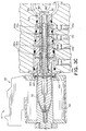
- Fig. 2 is a cross-sectional view of the control valve of Fig. 1;
- Figs. 3A-3C are cross-sectional views showing different operational positions of the control valve, some parts of which have been removed or modified for clarity of illustration;
- Fig. 4 is a cross-sectional view of another embodiment of a control valve of the present invention;
- Fig. 5 is a cross-sectional view of yet another embodiment of a control valve of the present invention;
- Figs. 6A and 6B are an end view and a cross-sectional view, respectively, of an alternate embodiment of the plunger; and
- Fig. 7 is a cross-sectional view of a further embodiment of the present invention.
-
- Referring now in detail and initially to Fig. 1, an actuator assembly is indicated generally at 10. The
assembly 10 comprises afluid power actuator 12, acontrol valve 14 for selectively providing fluid pressure to move theactuator 12, and afeedback mechanism 16 for providing feedback to thecontrol valve 14 regarding the position of theactuator 12. In the illustrated embodiment, thefluid power actuator 12 is a hydraulic actuator, but the same principles may be applied to other fluid actuators, e.g., pneumatic actuators. The position of theactuator 12 is controlled by the control valve which preferably is a solenoid-type valve that receives electrical control inputs from electrical control circuitry (not shown). Accordingly, thecontrol valve 14 has avalve portion 18 and asolenoid portion 20. - The
valve portion 18 of thecontrol valve 14 fits into amanifold 22 and may be held in place by any suitable means. The manifold has a pressure port 23 for connection to a high pressure fluid supply and a return or drain port 24 for connection to a low pressure fluid return or drain. In an exemplary embodiment, the length of the portion of the control valve that is inserted into the manifold is approximately 2.5 inches. Themanifold 22 also has connections forfluid lines manifold 22 and opposite sides of apiston 30 of theactuator 12. By connecting one of thefluid lines piston 30 is thereby moved (the fluid actuator is extended or retracted) to do useful work. - The
feedback mechanism 16 provides mechanical feedback to thecontrol valve 14 regarding the position of thepiston 30. The illustratedfeedback mechanism 16 includes arack 34 on arod 36 which is connected to thepiston 30. Apinion 38 meshes with therack 34 and thus translation of therod 36 is converted to rotational motion of thepinion 38. Thepinion 38 is connected to aneccentric cam 40 which rotates along with the pinion. Theeccentric cam 40 is in contact with thecontrol valve 14, so that rotation of theeccentric cam 40 causes displacement of a controlvalve contact surface 42 which is in contact therewith. - As explained in greater detail below, the
control valve 14 receives an input signal which shifts internal parts of the control valve so as to provide high pressure fluid through one of thefluid lines fluid lines piston 30 moves other internal parts of thecontrol valve 14 via thefeedback mechanism 16. After thepiston 30 has moved a given amount, the given amount being a function of the input signal magnitude, the internal parts of thecontrol valve 14 align so as to block further flow of fluid to theactuator 12, thus stopping further movement of the piston within the actuator. - Details of the
control valve 14 are shown in Fig. 2. Thesolenoid portion 20 includes aninput section 46 which receives an input such as an electrical signal. The input from theinput section 46 is then used in energizing acoil 50 which is at least partially within ahousing 52. Preferably the current used to energize thecoil 50 is a function of the strength of the input signal, and may be proportional to the input signal. For example, the input signal may be a variable current which is used to energize thecoil 50. - A
tube 56 is located within thehousing 52, surrounded by thecoil 50. Thetube 56 is held in a fixed position within thehousing 52 using atube flange 58 at one end of the tube which is pulled against anadapter 60 which is part of thehousing 52. This pulling is accomplished by means of anut 62 which mates with an externally-threadedopposite end 64 of thetube 56, thenut 62 being tightened againstend plate 66 of thehousing 52. - A
plunger 70 is slideable within thetube 56. Theplunger 70 has a conically-shaped end 72 which corresponds in shape to a conicalinterior surface 74 of thetube 56. At the conically-shaped end 72 astop 76 is coupled to theplunger 70, thestop 76 fitting into a narrow plunger bore 78. Thestop 76 has a stop recess 80 at its distal end for receiving aspring 82. Thespring 82 pushes thestop 76 into and against theplunger 70, and urges theplunger 70 rightward as shown in Fig. 2. The spring force may be adjusted using anadjustment mechanism 84, in which an externally-threadedadjuster 86 is positioned within anut 88 to increase or decrease the compression of thespring 82. - An O-
ring 90 provides sealing between theadjustment mechanism 84 and the interior of thetube 56. The O-ring is of a conventional design, and is made of conventional materials compatible with the fluid used and able to withstand the environment to which the control valve is to be exposed. For example, the O-ring material may and should be selected to be able to withstand temperature extremes to which the control valve will be subjected. - The
plunger 70 is preferably made of a ferromagnetic material such as steel. Generally, the other parts of thecontrol valve 14 are made out of steel, although it will be appreciated that other rigid metallic or non-metallic materials which are suitable for use may alternatively be employed. - Current in the
coil 50 induces a magnetic field which pulls theplunger 70 against the force of the spring 12 (leftward in Fig. 2). As is preferred, the magnetic field, and thus the magnetic force on theplunger 70, is linearly proportional to the current in thecoil 50. The spring force in thespring 72 is (to a first approximation) a linear function of the amount of compression. Therefore, beyond a certain minimum current in thecoil 50 which is required to initiate movement of theplunger 70, displacement of theplunger 70 increases linearly with increasing current in the solenoid. Those skilled in the art will appreciate that a non-linear response may be provided, if desired, by modifying the solenoid coil, plunger, and/or spring. - The
stop 76 prevents theplunger 70 from coming into contact with theinterior surface 74 of thetube 56. Such contact can lead to latching, a magnetic coupling of thetube 56 and theplunger 70. Further, thestop 76 has a stop bore 92 therethrough which allows free flow between the narrow plunger bore 78 and agap 94 between the conically-shapedend 72 and the conicalinterior surface 74. This equalizes pressure on both sides of theplunger 70 and prevents pressure changes in thegap 94 due to movement of theplunger 70; unequal pressures or pressure changes might affect the operating characteristics of the valve. - At its end 103 opposite the
stop 76, theplunger 70 has aplunger bore 102. Fitted in thebore 102 is anarrow end 98 of a primary ormain valve member 100, the main valve member being a part of thevalve portion 18. Thenarrow end 98 is connected to theplunger 70 by aroll pin 104. - As is preferred, the
main valve member 100 is in the form of a main spool. Themain spool 100 is internally slideable in a feedback valve sleeve orspool 106 which functions as a feedback valve member or follower of the illustratedcontrol valve 14. Thefeedback valve spool 106 is internally slideable in acage 110 that is fixedly connected to theadapter 60. The connection between thecage 110 and the adapter may include, for example, a threaded connection. An O-ring 112 provides sealing between thecage 110 and theadapter 60. - It is noted here that the
control valve 14 preferably is provided in the form of a cartridge that may be installed as a unit in the manifold 22 or other housing. Also, although not preferred, thesolenoid portion 20 may be replaced by other input mechanisms suitable for moving themain valve member 100 of thevalve portion 18 in response to a command prompt. - The
cage 110 provides the connection between thecontrol valve cartridge 14 and the manifold 22. Thecage 110 has series of holes 114a-114d corresponding to the locations of the passages 115a-115d in themanifold 22. The passages 115a-115d are respectively connected to the ports/fluid lines cage 110 as appropriate. Each of the series of holes 114 has one or more holes circumferentially spaced around thecage 110. Ahole 116 is used to provide pressure equalization on theplunger 70, as will be explained further below. - The
cage 110 has annular sealing ribs orprotrusions 118 between adjacent pairs of the holes 114a-114d. Each of the sealingribs 118 has an O-ring seal to prevent fluid from passing directly from one passage in the manifold 22 to another. Additional sealingribs 120 are provided in thecage 110 to prevent leakage of fluid outside of the manifold 22. The sealingribs manifold 22. This "stepped" cage and manifold are used to avoid the risk that the O-rings of the sealingribs manifold 22. - The
cage 110 has a circumferential groove along its interior surface for holding a retainingring 124 therein.Washers 126 are located on either side of the retainingring 124. The retainingring 124 and thewashers 126 provide a fixed stop that limits motion of theplunger 70. In addition, the retainingring 124 and thewashers 126 fix the location of one end of aspring 130, the other end of which presses on an end surface 132 of thefeedback spool 106. - The
feedback spool 106 has a series ofopenings 134a-134d and associated annular grooves which communicate with respective of the holes 114a-114d in thecage 110. The openings 134 are preferably somewhat longer than the holes 114 in order to maintain a fluid path between respective openings 134 and holes 114 as thefeedback spool 106 axially moves relative to thecage 110. The openings 134 may be, for example, a series of circumferentially-spaced holes about thefeedback spool 106 at axial locations corresponding to the holes 114. - An external sliding
surface 136 of thefeedback spool 106 fits closely against its counterpartinternal surface 138 of thecage 110 to prevent flow between thefeedback spool 106 and thecage 110. A close fit between thesurfaces feedback spool 106 or themain spool 100 which slides in the feedback spool. - The
feedback spool 106 has a closed cam follower end 140 which protrudes from the remainder of thecontrol valve 14. Thecontact surface 42 of theclosed end 140 is designed to contact thefeedback mechanism 16 such as the eccentric cam 40 (Fig. 1). The contact surface preferably is flat but it will be appreciated that the contact surface may have a curved or other non-flat shape if desired. - The
feedback spool 106 has attached thereto, at an annular groove, a retainingring 144. The retainingring 144 has an outside diameter greater than the inside diameter of thecage 110. This limits the travel of thefeedback spool 106 and thereby limits the amount by which theclosed end 140 protrudes from the remainder of thecontrol valve 14. - Still referring to Fig. 2, the
main spool 100 is hollow, having a narrow (small diameter) spool bore 148 in itsnarrow spool end 98 and a wide spool bore 150 in itswide spool end 154. Thebores main spool 100, as well as providing a passageway for fluid to flow between either end of themain spool 100 andspool holes 158 in themain spool 100. - The
holes 158 communicate with a passage 115a in the manifold 22 which is maintained at relatively constant pressure, such as at a system drain (return) pressure, via theopenings 134a in thefeedback spool 106 and the cage holes 114a in thecage 110. Thus thegap 94 between the conically-shapedend 72 and the conicalinterior surface 74 is maintained at that same pressure, since thegap 94 and the spool holes 158 are linked via the stop bore 92, the plunger bores 78 and 102, and the spool bores 148 and 150. The opposite end 103 of theplunger 70 is also maintained at the same pressure, since avolume 164 is communication with the opposite end 103 of theplunger 70 via central apertures in the retainingring 124 and thewashers 126, and thevolume 164 is also in communication with the passage 115a via theholes 116 in thecage 110. Thus both sides of theplunger 70 are maintained at the same pressure, so that movement of the plunger does not cause pressure changes on one or both sides thereof that might affect the operating characteristics of thevalve 14, and further to pressure balance the plunger. - It will be appreciated that the valve may alternatively be configured for using any of the passages in the manifold as the source of the pressure for equalizing pressure on both sides of the plunger, and that the pressure source for the equalization need not provide constant pressure.
- The
main spool 100 has recessed regions (annular grooves) 166a and 166b and cover portions (annular lands) 170a and 170b. The recessedregions main spool 100 and thecage 110, can provide a flow pathway or passageway linking adjacent of theopenings 134a-134d in thefeedback spool 106. The recessedregions main spool 100, but may for example be grooves or channels in a region which is otherwise not recessed. - The
cover portions respective openings feedback spool 106. Thus when themain spool 100 and thefeedback spool 106 are positioned such that thecover portions openings actuator 12, and the position of theactuator 12 is maintained. This no-flow condition is referred to as a "null" condition of thevalve 14. Such a null condition is the default condition when no input signal is applied to the control valve. A null condition also occurs when thecover portions openings feedback spool 106 by thefeedback mechanism 16 when the desired position of thepiston 30 is achieved, as explained in greater detail below. - It will be appreciated that alternatively the control valve may provide flow when no current or other input is provided, rather than being in a null condition.
- Preferably, the
cover portions respective openings cover portions respective openings control valve 14 to an input signal. More overlap means more motion of themain spool 100 is required to initiate flow. - Figs. 3A-3C illustrate operation of the fluid
control valve cartridge 14. In Fig. 3A thecontrol valve 14 is shown with no current applied tosolenoid portion 20, and with theactuator 12 fully retracted. Thevalve 14 is in a null position, withcover portions respective openings control valve 14. The actuator being fully retracted corresponds to theeccentric cam 40 oriented so thatsurface 42 offeedback spool 106 protrudes a maximum amount from the remainder of thevalve 14, with retainingring 144 against its stop oncage 110. - Fig. 36 shows the configuration of the
control valve 14 when an input current has been applied and theactuator 12 is extending. The magnetic field produced by the current through thecoil 50 causes plunger 70 to move leftward, further compressingspring 72. Themain spool 100 likewise moves to the left. This causes thecover portions openings valve 14 for fluid to flow to and from theactuator 12. - Fluid from
high pressure passage 115c in the manifold 22 flows throughhole 114c in thecage 110, throughopenings 134c in thefeedback spool 106, along recessedregion 166b of themain spool 100, throughopenings 134b and holes 114b topassage 115b which is linked to port of the actuator for extending the actuator. This path is indicated by arrows 174 in Fig. 3B. - Fluid from the other port of the actuator enters
passage 115d of the manifold, passes throughholes 114d andopenings 134d intobore 150 inopen end 154 of themain spool 100, along thebore 150 and throughspool holes 158,openings 134a, and holes 114a into drain line (low pressure) passage 115a. This path is indicated byarrows 176. - In response to the movement of the actuator the
eccentric cam 40, part of thefeedback mechanism 16, rotates counterclockwise about anaxis 180. This rotation of theeccentric cam 40 pushes thefeedback spool 106 leftward, thereby causing thecover portions openings feedback spool 106 by thefeedback mechanism 16 causes thevalve 14 to again reach a null condition, as shown in Fig. 3C. - In Fig. 3C it is seen that the
feedback spool 106 has moved leftward, with the retainingring 144 off its stop on thecage 110. Thecover portions openings - As the
eccentric cam 40 rotates, friction forces between thecam 40 and thecontact surface 42 of thefeedback spool 106 will exert a lateral force on thefeedback spool 106. In addition rotation of theeccentric cam 40 causes acontact point 182 between thecam 40 and thecontact surface 42 to move away from the centerline of thefeedback spool 106, which also leads to a lateral force on thefeedback spool 106. - Since the
feedback spool 106 is between themain spool 100 and thecage 110, these lateral forces do not tend to trap the main spool or cause it to bind, as might happen if the main spool was between thecage 110 and the feedback spool. However, it will be appreciated that the feedback spool might alternatively be slideable within the main spool, rather than vice versa, if the risk of binding or added wear was considered acceptable. - It will be appreciated that the
actuator 12 may be retracted in whole or in part by reversing the steps outlined above. Making reference to the null extended condition of thevalve 14 shown in Fig. 3C, reducing or removing the input current would cause the magnetic field produced by thecoil 50 to be reduced or eliminated, which would cause thespring 82 to reposition theplunger 70 and themain spool 100 rightward, with themain spool 100 sliding within thefeedback spool 106. - Movement of the
main spool 100 causes thecover portions openings passages 115a and 115b connected together via a flow passageway which includes the recessedregion 166a, and thepassages region 166b. - As the actuator retracts the
eccentric cam 40 rotates clockwise due to the action of thefeedback mechanism 16. This rotation of theeccentric cam 40 allows thefeedback spool 106 to move rightward under the action of thespring 130. This rightward movement of thefeedback spool 106 causes thecover portions openings actuator 12 has reached its desired position and thevalve 14 is again in a null configuration, with no further flow to or from the actuator. - In an exemplary application, the above-described control valve may be used as part of a system for adjusting vanes of a turbocharger via a hydraulic actuator. Turbocharger temperatures can reach 1200°F, and an electronic feedback system for such an actuator would be unable to withstand the thermal environment created by close proximity to the turbocharger.
- It will be appreciated that the embodiments described heretofore are merely exemplary, and that numerous variations that would occur to one skilled in the art are embraced by the invention. For example, numerous parts are described above as involving narrower and wider portions and/or bores, but it will be appreciated that relative widths of the portions and/or the bores may be reversed or otherwise altered.
- Further, it will be appreciated that many variations of the configuration of the ports in the manifold are possible, although it is preferable that the pressure/drain passages alternate with the passages for the hydraulic lines to the actuator.
- While the embodiments described above have been generally related to a control valve for a hydraulic actuator, a control valve embodiying the present invention may also be usable with a pneumatic system for delivering a pressurized gas in order to do work.
- The invention may be used with a wide variety of work-performing devices in place of the actuator described above, as long as the work-performing device is able to provide movement that can be used for the feedback mechanism.
- The feedback mechanism may include a wide variety of mechanical couplings and/or linkages, for instance belts, pulleys, levers, many varieties of gears, etc. The feedback mechanism may have a linear or nonlinear feedback between movement of the actuator or other device and movement of the feedback follower. The feedback mechanism may provide feedback which moves the cam follower substantially the same distance that the actuator moves.
- A mechanical input device may be substituted for the solenoid portion, if desired, with the design altered as necessary.
- It will be understood that a variety of known resilient biasing devices may be used in place of the coil springs shown in the illustrated embodiments.
- What follows below are descriptions of some alternate embodiment cartridge control valves of the present invention, description of some similar features being omitted below for the sake of brevity.
- Fig. 4 shows a
control valve 214 which has asolenoid portion 215 with ahousing 218 which has a foldedportion 220 for holding a washer 222 in place at one end. Thesolenoid portion 215 also has atube 226 which is crimped onto apole piece 228, with an O-ring 230 sealing the connection between thetube 226 and thepole piece 228. This collection of parts substitutes for thetube 56 of thecontrol valve 14. -
Plunger 240 has a T-shapedslot 242 for receiving a T-shapedprotrusion 244 on one end of a main spool 250. Theplunger 240 has acentral bore 254 therethrough, thebore 254 being in communication with theslot 242. Apin 258 is located in thebore 254. Aspring 260 between thepin 258 and theprotrusion 244 provides biasing for the location of theplunger 240 and the main spool 250. - Referring to Fig. 5, an alternate embodiment
cartridge control valve 414 has acam follower 420 which slides within a main spool orsleeve 422. Aspring 430 between thecam follower 420 and the main spool orsleeve 422 provides a force which biases thecam follower 420 to protrude from the remainder of thecontrol valve 414. - Figs. 6A and 6B show an
alternate embodiment plunger 470 which hasgrooves 472 in an axial direction along its external surface. Thegrooves 472 allow the pressures on both sides of theplunger 470 to be maintained equal without the necessity of boring a hole or otherwise providing a flow passage through the plunger. - Referring to Fig. 7, a
feedback control system 610 is shown in which a fluid actuator 612 has anintegral feedback member 614 directly in contact with acontact surface 618 of acontrol valve 620, thecontrol valve 620 being a valve of the type described above. The actuator 612 and thecontrol valve 620 may both be housed in a manifold 624, with fluid connections between the actuator 612 and thecontrol valve 620 beingpassages manifold 624. The manifold has avent 630 which is in communication with avolume 632 in which thefeedback member 614 and thecontrol valve 620 meet. - An input signal to the
control valve 620 causes thepassages passages feedback member 614, which in turn moves thecontact surface 618 which is part of a feedback follower or spool. In a manner similar to that described above in connection with Figs. 3A-3C, thecontrol valve 620 reaches a null state when the desired actuator position is reached. - It will be appreciated that the feedback member may alternatively be a separate part that is attached or otherwise connected to the fluid actuator. It will further be appreciated that the actuator and the control valve may be housed in different manifolds, or that fluid lines may used in connecting the actuator and the control valve, if desired.
- Although the invention has been shown and described with respect to a certain preferred embodiment or embodiments, equivalent alterations and modifications will occur to others skilled in the art upon the reading and understanding of this specification and the annexed drawings. In particular regard to the various functions performed by the above described elements (components, assemblies, devices, compositions, etc.), the terms (including a reference to a "means") used to describe such elements are intended to correspond, unless otherwise indicated, to any element which performs the specified function of the described element (i.e., that is functionally equivalent), even though not structurally equivalent to the disclosed structure which performs the function in the herein illustrated exemplary embodiment or embodiments of the invention. In addition, while a particular feature of the invention may have been described above with respect to only one or more of several illustrated embodiments, such feature may be combined with one or more other features of the other embodiments, as may be desired and advantageous for any given or particular application.
Claims (13)
- A single-stage fluid flow cartridge control valve, comprising:a cage having openings therethrough;a first valve member internally slideable within the cage;a second valve member internally slideable within the first valve member; andan input mechanism coupled to one of the valve members for moving the one of the valve members;
wherein movement of the one of the valve members selectively opens fluid flow pathways between pairs of the openings, and movement of the other of the valve members selectively closes the fluid flow pathways. - The flow control valve of claim 1, wherein the first valve member is the other of the valve members, and the second valve member is the one of the valve members.
- The flow control valve of claim 2, wherein the second valve member is a main spool having a bore forming part of the fluid flow pathways.
- The flow control valve of claim 2 or 3, wherein the first valve member is a cam follower.
- The flow control valve of claim 4, further comprising a spring which biases position of the cam follower.
- The flow control valve of any of the preceding claims, wherein the input mechanism is a solenoid which includes a coil and a plunger within the coil which moves in response to a magnetic field induced by current flowing through the coil.
- The flow control valve of claim 6, further comprising a spring operatively coupled to the plunger for biasing position of the plunger.
- The flow control valve of any of the preceding claims, in combination with an actuator operatively coupled to the valve, and a feedback mechanism coupled to the actuator and coupled to the other of the valve members.
- The flow control valve of claim 8, wherein the feedback mechanism is in contact with a contact surface of the other of the valve members.
- The flow control valve of any of the preceding claims, wherein the cage is a stepped cage.
- A fluid flow control valve, comprising:a cage having openings therethrough;a first valve member internally slideable within the cage;a second valve member internally slideable within the first valve member, the second valve member having a bore therein and holes therethrough in communication with the bore; andan input mechanism coupled to one of the valve members for moving the one of the valve members;
wherein movement of the one of the valve members selectively opens fluid flow pathways between pairs of the openings and movement of the other of the valve members selectively closes the fluid flow pathways, and wherein the holes and the bore are part of a fluid flow pathway between non-adjacent openings. - An actuator assembly comprising an actuator for moving an external member, a control valve which controllably provides fluid to effect movement of the actuator, and a mechanical feedback device which provides actuator position feedback to the control valve.
- A method of positioning a hydraulic actuator in response to an input signal, comprising the steps of:opening flow pathways in a control valve by moving a main spool of the control valve a distance which is a function of the input signal;sending pressurized fluid to one side of the actuator, and draining fluid from the other side of the actuator, through the pathways; andclosing the pathways after the actuator has reached a desired position by moving a feedback follower which is mechanically coupled to the actuator.
Applications Claiming Priority (2)
| Application Number | Priority Date | Filing Date | Title |
|---|---|---|---|
| US13520499P | 1999-05-21 | 1999-05-21 | |
| US135204P | 1999-05-21 |
Publications (1)
| Publication Number | Publication Date |
|---|---|
| EP1054161A1 true EP1054161A1 (en) | 2000-11-22 |
Family
ID=22467008
Family Applications (1)
| Application Number | Title | Priority Date | Filing Date |
|---|---|---|---|
| EP20000304293 Ceased EP1054161A1 (en) | 1999-05-21 | 2000-05-22 | Control valve with mechanical feedback and method for controlling fluid flow |
Country Status (2)
| Country | Link |
|---|---|
| US (1) | US6481463B1 (en) |
| EP (1) | EP1054161A1 (en) |
Cited By (2)
| Publication number | Priority date | Publication date | Assignee | Title |
|---|---|---|---|---|
| WO2004044436A1 (en) * | 2002-11-07 | 2004-05-27 | Honeywell International, Inc. | Electro-hydraulic actuator with mechanical servo position feedback |
| US8029664B2 (en) | 2008-06-26 | 2011-10-04 | Hamilton Sundstrand Corporation | Wash filter with wash velocity control cone |
Families Citing this family (14)
| Publication number | Priority date | Publication date | Assignee | Title |
|---|---|---|---|---|
| US6883320B2 (en) * | 2003-07-08 | 2005-04-26 | G. W. Lisk Company, Inc. | Control system regulating air flow to engine intake |
| US8398004B2 (en) * | 2009-09-17 | 2013-03-19 | Parker-Hannifin Corporation | Hydraulic drive system for sand and salt spreaders |
| CN105593648B (en) | 2013-07-12 | 2019-11-05 | 约翰·C·卡拉马诺斯 | fluid control measuring device |
| US10175669B2 (en) | 2013-07-12 | 2019-01-08 | Best Technologies, Inc. | Fluid control measuring and controlling device |
| US10030882B2 (en) | 2013-07-12 | 2018-07-24 | Best Technologies, Inc. | Low flow fluid controller apparatus and system |
| US10088821B2 (en) | 2013-07-12 | 2018-10-02 | Best Technologies, Inc. | Self balancing air fixture |
| US11815923B2 (en) | 2013-07-12 | 2023-11-14 | Best Technologies, Inc. | Fluid flow device with discrete point calibration flow rate-based remote calibration system and method |
| US11429121B2 (en) | 2013-07-12 | 2022-08-30 | Best Technologies, Inc. | Fluid flow device with sparse data surface-fit-based remote calibration system and method |
| US9915368B2 (en) | 2015-11-06 | 2018-03-13 | Caterpillar Inc. | Electrohydraulic valve having dual-action right-angle pilot actuator |
| US9803661B2 (en) | 2015-11-06 | 2017-10-31 | Caterpillar Inc. | Valve having right-angle proportional and directional pilot actuators |
| US9897228B2 (en) | 2015-11-06 | 2018-02-20 | Caterpillar Inc. | Valve having opposing right-angle actuators |
| DE102018216831A1 (en) * | 2018-10-01 | 2020-04-02 | Robert Bosch Gmbh | Control device for pump pressure and volume flow with concentric control spools |
| CN109999724A (en) * | 2019-04-22 | 2019-07-12 | 苏州高迈新能源有限公司 | Flow control system and experimental provision |
| US11536393B2 (en) * | 2021-04-12 | 2022-12-27 | Fisher Controls International Llc | Travel feedback system |
Citations (4)
| Publication number | Priority date | Publication date | Assignee | Title |
|---|---|---|---|---|
| US2969808A (en) * | 1958-05-22 | 1961-01-31 | Cincinnati Milling Machine Co | Two-stage valve |
| DE2332125A1 (en) * | 1973-06-25 | 1975-01-23 | Kelor Ltd | Pneumatic servo motor, using return springs - with piston-operated valve units moving in opposite directions |
| US4177713A (en) * | 1975-05-12 | 1979-12-11 | The Garrett Corporation | Electrohydraulic proportional actuator apparatus |
| WO1997013074A2 (en) * | 1995-09-30 | 1997-04-10 | Eckehart Schulze | Electrohydraulic control valve arrangement |
Family Cites Families (8)
| Publication number | Priority date | Publication date | Assignee | Title |
|---|---|---|---|---|
| US2526709A (en) * | 1945-11-29 | 1950-10-24 | Sperry Corp | Fluid operated motor valve |
| US2771907A (en) * | 1949-01-29 | 1956-11-27 | Joy Mfg Co | Pilot controlled piston type reversing valve |
| US3875849A (en) * | 1972-09-11 | 1975-04-08 | Applied Power Inc | Electro-hydraulic proportional servo actuator |
| US4011891A (en) * | 1975-08-06 | 1977-03-15 | Applied Power Inc. | Proportional flow control valve |
| US4375942A (en) * | 1981-04-21 | 1983-03-08 | Dynes/Rivett Inc. | Tilting cam, rotating barrel pump |
| US4526201A (en) * | 1982-11-04 | 1985-07-02 | Spectra-Physics, Inc. | Four-way valve with internal pilot |
| US5836335A (en) * | 1991-08-19 | 1998-11-17 | Fluid Power Industries, Inc. | Proportional pressure control valve |
| US5848612A (en) * | 1997-11-25 | 1998-12-15 | Sargent Controls & Aerospace/Dover Diversified Inc. | Servovalve employing a rotatable feedback linkage |
-
2000
- 2000-05-19 US US09/574,544 patent/US6481463B1/en not_active Expired - Lifetime
- 2000-05-22 EP EP20000304293 patent/EP1054161A1/en not_active Ceased
Patent Citations (4)
| Publication number | Priority date | Publication date | Assignee | Title |
|---|---|---|---|---|
| US2969808A (en) * | 1958-05-22 | 1961-01-31 | Cincinnati Milling Machine Co | Two-stage valve |
| DE2332125A1 (en) * | 1973-06-25 | 1975-01-23 | Kelor Ltd | Pneumatic servo motor, using return springs - with piston-operated valve units moving in opposite directions |
| US4177713A (en) * | 1975-05-12 | 1979-12-11 | The Garrett Corporation | Electrohydraulic proportional actuator apparatus |
| WO1997013074A2 (en) * | 1995-09-30 | 1997-04-10 | Eckehart Schulze | Electrohydraulic control valve arrangement |
Cited By (4)
| Publication number | Priority date | Publication date | Assignee | Title |
|---|---|---|---|---|
| WO2004044436A1 (en) * | 2002-11-07 | 2004-05-27 | Honeywell International, Inc. | Electro-hydraulic actuator with mechanical servo position feedback |
| US6955113B2 (en) | 2002-11-07 | 2005-10-18 | Honeywell International Inc. | Electro-hydraulic actuator with mechanical servo position feedback |
| US8029664B2 (en) | 2008-06-26 | 2011-10-04 | Hamilton Sundstrand Corporation | Wash filter with wash velocity control cone |
| US8313656B2 (en) | 2008-06-26 | 2012-11-20 | Hamilton Sundstrand Corporation | Wash filter with wash velocity control cone |
Also Published As
| Publication number | Publication date |
|---|---|
| US6481463B1 (en) | 2002-11-19 |
Similar Documents
| Publication | Publication Date | Title |
|---|---|---|
| US6481463B1 (en) | Control valve with mechanical feedback and method for controlling fluid flow | |
| US7341236B2 (en) | Pilot operated valve with a pressure balanced poppet | |
| US8256739B2 (en) | Poppet valve operated by an electrohydraulic poppet pilot valve | |
| EP1050703B1 (en) | Pilot operated control valves | |
| US6966329B2 (en) | Proportional pilot-operated flow control valve | |
| US5878647A (en) | Pilot solenoid control valve and hydraulic control system using same | |
| US7984890B2 (en) | Pilot operated valve with fast closing poppet | |
| US5921279A (en) | Solenoid operated dual spool control valve | |
| US4491153A (en) | Pressure reducing valve | |
| US20070199601A1 (en) | Directional or flow control valve | |
| US6073652A (en) | Pilot solenoid control valve with integral pressure sensing transducer | |
| US20140026985A1 (en) | Electro-proportional pilot operated poppet valve with pressure compensation | |
| US6843266B2 (en) | Regulator with erosion resistant seal assemblies | |
| EP0941408B1 (en) | Actuator with failfixed zero drift | |
| JPH11264403A (en) | Integrated electro-hydraulic actuator | |
| CN110337555B (en) | Solenoid proportional valve | |
| CN222910941U (en) | Valve | |
| JP6592300B2 (en) | Solenoid valve with check valve with bypass passage | |
| CN101387311A (en) | Pilot Operated Valve with Pressure Balanced Poppet | |
| WO2015131915A1 (en) | Valve assembly | |
| WO2003002897A1 (en) | Spring valve implemented flow control valves | |
| US20020023683A1 (en) | Regulator with segmented body | |
| EP1067293A2 (en) | Electro-hydraulic actuator and method for controlling actuator position | |
| EP1054164A2 (en) | Actuator | |
| JP3626634B2 (en) | Valve device |
Legal Events
| Date | Code | Title | Description |
|---|---|---|---|
| PUAI | Public reference made under article 153(3) epc to a published international application that has entered the european phase |
Free format text: ORIGINAL CODE: 0009012 |
|
| AK | Designated contracting states |
Kind code of ref document: A1 Designated state(s): AT BE CH CY DE DK ES FI FR GB GR IE IT LI LU MC NL PT SE |
|
| AX | Request for extension of the european patent |
Free format text: AL;LT;LV;MK;RO;SI |
|
| 17P | Request for examination filed |
Effective date: 20010518 |
|
| AKX | Designation fees paid |
Free format text: AT BE CH CY DE DK ES FI FR GB GR IE IT LI LU MC NL PT SE |
|
| 17Q | First examination report despatched |
Effective date: 20030813 |
|
| 17Q | First examination report despatched |
Effective date: 20030813 |
|
| STAA | Information on the status of an ep patent application or granted ep patent |
Free format text: STATUS: THE APPLICATION HAS BEEN REFUSED |
|
| 18R | Application refused |
Effective date: 20071230 |