EP1054153A2 - Closed loop spark control - Google Patents
Closed loop spark control Download PDFInfo
- Publication number
- EP1054153A2 EP1054153A2 EP00303107A EP00303107A EP1054153A2 EP 1054153 A2 EP1054153 A2 EP 1054153A2 EP 00303107 A EP00303107 A EP 00303107A EP 00303107 A EP00303107 A EP 00303107A EP 1054153 A2 EP1054153 A2 EP 1054153A2
- Authority
- EP
- European Patent Office
- Prior art keywords
- spark timing
- borderline
- signal
- spark
- staircase
- Prior art date
- Legal status (The legal status is an assumption and is not a legal conclusion. Google has not performed a legal analysis and makes no representation as to the accuracy of the status listed.)
- Withdrawn
Links
- 238000002485 combustion reaction Methods 0.000 claims abstract description 29
- 238000000034 method Methods 0.000 claims abstract description 23
- 238000012360 testing method Methods 0.000 claims description 8
- 230000000979 retarding effect Effects 0.000 claims description 5
- 238000005259 measurement Methods 0.000 abstract description 2
- 238000001514 detection method Methods 0.000 description 3
- 238000012062 charged aerosol detection Methods 0.000 description 2
- 238000001360 collision-induced dissociation Methods 0.000 description 2
- 238000011960 computer-aided design Methods 0.000 description 2
- 230000000694 effects Effects 0.000 description 2
- 241000607479 Yersinia pestis Species 0.000 description 1
- 238000004364 calculation method Methods 0.000 description 1
- 230000006835 compression Effects 0.000 description 1
- 238000007906 compression Methods 0.000 description 1
- 238000011217 control strategy Methods 0.000 description 1
- 238000013480 data collection Methods 0.000 description 1
- 238000010586 diagram Methods 0.000 description 1
- 239000000446 fuel Substances 0.000 description 1
- 230000006870 function Effects 0.000 description 1
- 238000004519 manufacturing process Methods 0.000 description 1
- 230000005055 memory storage Effects 0.000 description 1
- TVMXDCGIABBOFY-UHFFFAOYSA-N octane Chemical compound CCCCCCCC TVMXDCGIABBOFY-UHFFFAOYSA-N 0.000 description 1
- 239000000523 sample Substances 0.000 description 1
- 238000005070 sampling Methods 0.000 description 1
- 230000001052 transient effect Effects 0.000 description 1
Images


Classifications
-
- F—MECHANICAL ENGINEERING; LIGHTING; HEATING; WEAPONS; BLASTING
- F02—COMBUSTION ENGINES; HOT-GAS OR COMBUSTION-PRODUCT ENGINE PLANTS
- F02P—IGNITION, OTHER THAN COMPRESSION IGNITION, FOR INTERNAL-COMBUSTION ENGINES; TESTING OF IGNITION TIMING IN COMPRESSION-IGNITION ENGINES
- F02P5/00—Advancing or retarding ignition; Control therefor
- F02P5/04—Advancing or retarding ignition; Control therefor automatically, as a function of the working conditions of the engine or vehicle or of the atmospheric conditions
- F02P5/145—Advancing or retarding ignition; Control therefor automatically, as a function of the working conditions of the engine or vehicle or of the atmospheric conditions using electrical means
- F02P5/15—Digital data processing
- F02P5/152—Digital data processing dependent on pinking
- F02P5/1522—Digital data processing dependent on pinking with particular means concerning an individual cylinder
-
- Y—GENERAL TAGGING OF NEW TECHNOLOGICAL DEVELOPMENTS; GENERAL TAGGING OF CROSS-SECTIONAL TECHNOLOGIES SPANNING OVER SEVERAL SECTIONS OF THE IPC; TECHNICAL SUBJECTS COVERED BY FORMER USPC CROSS-REFERENCE ART COLLECTIONS [XRACs] AND DIGESTS
- Y02—TECHNOLOGIES OR APPLICATIONS FOR MITIGATION OR ADAPTATION AGAINST CLIMATE CHANGE
- Y02T—CLIMATE CHANGE MITIGATION TECHNOLOGIES RELATED TO TRANSPORTATION
- Y02T10/00—Road transport of goods or passengers
- Y02T10/10—Internal combustion engine [ICE] based vehicles
- Y02T10/40—Engine management systems
Definitions
- This invention relates to engine control systems in general and more particularly to a closed loop spark control system and algorithm operating around borderline knock spark timing and using the characteristics of a sensor related to combustion quality to determine the borderline knock spark timing.
- Spark timing in current production engines may be under open loop or closed loop control. If open loop, the spark timing is determined by calibrated look-up tables and calculated algorithms based on overall engine operating parameters and control inputs. If this method is used, the spark timing must be conservative (retarded) enough in order that the engine will not knock under worst-case conditions of compression ratio, fuel octane, combustion chamber deposits, and humidity. Since worst-case conditions are rare, retarded spark timing most or possibly all of the time will artificially reduce engine torque/efficiency.
- spark timing under closed loop control with a knock detection system.
- spark advance the same open loop spark tables are used to determine spark advance, and if knock is detected spark is retarded from that spark advance. Spark is then advanced if no further knocking events are detected until the original reference is reached. If more knocking events are detected, then spark is retarded further.
- the spark timing look-up tables contain upper and lower limits for different overall engine operating parameters, and feedback from the knock detector is used to find the optimal spark advance within those limits.
- the desired setpoint is the limit of knock audibility or the threshold of knock-induced piston damage or maximum engine torque, whichever comes first.
- the control strategy is arranged so that the knock detection system classifies each combustion event as knocking or non-knocking. If a combustion event is classified as non-knocking, the spark timing is advanced or maintained for the next engine cycle. However, if a combustion event is classified as knocking, the spark timing is retarded for the next engine cycle.
- knock detection system classifies each combustion event as knocking or non-knocking. If a combustion event is classified as non-knocking, the spark timing is advanced or maintained for the next engine cycle. However, if a combustion event is classified as knocking, the spark timing is retarded for the next engine cycle.
- Some systems maintain running averages and statistical measures of the individual cycle results for self-calibration purposes, and it is common to treat the knocking and non-knocking cycles differently in these statistical calculations.
- a method for determining borderline knock spark timing in an internal combustion engine comprising the steps of: setting spark advance at a value equal to a predetermined borderline spark timing angle minus a fixed number of crankshaft angle degrees; staircase advancing the spark timing angle by an incremental number of crankshaft angle degrees; measuring the signal amplitude of a combustion-related event at each staircase step; calculating the slope between the measured signal amplitude at each staircase step with the prior staircase step signal amplitude; and then identifying the staircase step angular value as the borderline knock spark timing wherein the calculated slope becomes greater than a predetermined value of slope.
- a spark timing system for determining and storing borderline knock spark timing for generating the maximum torque in an internal combustion engine: a look-up table responding to engine speed, engine load and engine cylinder number for generating a borderline knock spark timing signal; storage means having predetermined spark retarding signal responsive to said borderline knock spark timing signal generated by said look-up table for generating a new testing spark timing signal retarded from said borderline knock spark timing signal; means responsive to said new testing spark timing signal for generating a staircase timing signal extending from said new testing spark timing crank angle degree to a predetermined spark timing advanced crank angle degree; ignition timing means responsive to said staircase timing signal for generating an ignition event at each staircase step; a sensor responding to combustion quality events in said cylinder and for generating an electrical signal having a signal amplitude; means for calculating the slope value between said signal amplitudes at adjacent steps; identifying means responding to all said calculated slope values for generating a timing signal representing the crank angle degrees when a calculated slope value is greater than a predetermined slope value
- a common feature of the existing prior art systems is that the knocking/non-knocking classification does not make use of a valuable piece of information, namely the value of spark timing in effect when each cycle was measured. It is therefore a principal advantage of the system to control spark timing directly by the powertrain control module, wherein the value of spark timing in effect when each cycle is measured is readily available on a cycle resolved basis.
- the method embodying the invention sets the spark timing at a value equal to a predetermined borderline spark timing angle minus a fixed number of crankshaft angle degrees. Spark timing is advanced in a staircase manner by an incremental number of crankshaft angle degrees in each step. The signal amplitude of a combustion-related event at each staircase step is measured. The slope is calculated between the measured signal amplitude at each staircase step with the prior staircase step signal amplitude. Finally the staircase step angular value is identified as the borderline knock spark timing wherein the calculated slope becomes greater than a predetermined value of slope.
- An embodiment of the present invention discloses a closed-loop spark control system and algorithm that uses a knock sensor, or other similar sensor, to determine borderline knock spark advance. Spark advance is varied within upper and lower limits in a predefined manner and one or more characteristics of the knock detector signal are recorded as a function of spark advance. Examination of this spark timing dependence reveals the location of borderline knock. In the preferred embodiment the maximum amplitude of a detected signal as a result of a combustion event at a given spark angle is the knock sensor parameter used for spark control, but there may be other, equally appropriate characteristics that could be used. Once borderline knock is determined, spark timing is fixed at or near the borderline knock until engine conditions such as speed and load change.
- the flow chart of Fig. 1 represents the steps of an algorithm necessary to determine the borderline knock spark advance for a given cylinder at a steady speed and load.
- the first step 10 it is determined if the knock system is active. If it is not 12, the program exits. If it is active 14, then the decision output is YES and the flow chart continues to the second step 16.
- a knock sensor 18 (Fig. 4).
- a sensor 18 may be one of a variety of sensors which respond to a quality combustion event.
- a cylinder pressure sensor is one such sensor as are various accelerometers, an in-cylinder ionisation probe or any other sensor that is capable of detecting an engine knock characteristic.
- Other combustion intensity sensors may measure engine block vibration including exhaust temperature sensors.
- the second step 18 it is determined if the engine is at a fixed speed and load. If YES 20, then the flow chart continues and if NO 22, then the system will exit to the normal spark control or transient knock detection 24.
- a timer will be used to determine if enough time has elapsed since the last update. If enough time has elapsed, YES 30, so that the next update does not fall too close to the last data collection, the flow chart advances to the fourth step 32.
- the spark advance is set to a value equal to borderline knock spark timing minus some fixed amount of crank angle degrees, CAD.
- Fig. 3 illustrates a graphic representation of this step of retarding the spark from a present spark timing of fifteen crank angle degrees (15 CAD) a predetermined number of crank angle degrees.
- cylinder "A" is retarded to twelve and one-half crank angle degrees.
- the knock sensor 18 measures a signal amplitude of a combustion-related event at this new spark timing. This amplitude is stored.
- the spark timing is advanced by a staircase signal 53 by a predetermined number of crank angle degrees.
- each step of the staircase signal is one-half CAD and the sensor measures the signal amplitude of the combustion-related event at this new spark timing. The amplitude of the signal is compared with safe amplitude in the sixth step 36.
- a new borderline spark timing value is selected.
- the process takes the borderline spark timing from the value used in the sixth step 36 and retards that value by amount equal to a designed "safe spark” value in the step 42 of Fig 2. This is now a new borderline knock spark timing value and the process then exits 44 and returns to the first step 10 in Fig. 1.
- Fig 1 If the amplitude is less than the safe amplitude 46, the process of Fig 1 continues until the spark timing has advanced beyond where the engine designer believes that borderline knock spark timing occurs. This is illustrated in steps seven to twelve, 48-58 in Fig. 1.
- the result of the tenth step 54 is illustrated as seventeen CAD that is one CAD beyond a designed value of borderline knock, "BLD".
- the slope between each of these stored amplitudes is calculated in the eleventh step 56 and compared to a predetermined slope. When the first slope is found to be greater than the predetermined slope, the number of CAD at the beginning of the slope is determined to be the borderline knock spark timing for the tested cylinder at the speed and load values. This is illustrated in the twelfth step 58.
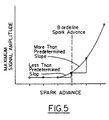
- Fig. 5 illustrates in graphic form, the concept of slopes of each step of the staircase signal. As the steps advance toward the borderline knock, the amplitude becomes greater.
- the slope value of the step is defined as being from the beginning of the step until the height of the amplitude at the end of the step.
- the ordinate of Fig 5 is the maximum signal amplitude and the abscissa is the spark advance in CAD.
- spark timing is retarded from the borderline knock spark timing signal.
- the borderline knock spark timing is defined as the spark advance at the beginning of the step.
- the algorithm in the sixth step 36, checks the measured amplitude with a "safe" amplitude as determined by the engine designer.
- the flow chart moves to the seventh step 48 and repeats the steps of measuring and saving for a predetermined number of successive ignition or combustion events before advancing the spark timing.
- the saved data in the form of the signal amplitudes is processed to determine borderline knock spark timing.
- borderline knock spark timing is determined, the spark advance for that cylinder at that speed and load is stored in a look-up table and is used for the spark advance under the conditions set or found in the second step 16.
- the algorithm repeats the fifth step 36 through the twelfth step 58 with the cylinder number changed.
- the process of retarding the spark advance and measuring the signal amplitude and saving the measurements for the desired number of samples is begun. This continues until the new cylinder spark advance is greater than borderline knock spark timing plus a predetermined number of CADs is reached. At that time the signal amplitude slopes are determined and the borderline knock spark timing is determined for that cylinder and stored in the look-up table.
- FIG. 4 there is illustrated a spark timing control system for determining and storing spark timing adjacent to borderline knock for generating the maximum torque/efficiency in an internal combustion engine.
- An engine speed sensor 60 measures engine speed and generates an engine speed signal.
- An engine load sensor 62 measures engine load and generates an engine load signal.
- the present engine cylinder 64 is identified and a signal is generated identifying the engine cylinder.
- a look-up table 66 responds to the engine speed, engine load and cylinder signals and outputs a signal to a spark-timing generator 68 for generating a spark timing signal.
- a memory storage 70 has a predetermined spark advance signal responsive to the spark timing signal generated by the look-up table 66 to generate a new testing spark timing signal advanced from the spark timing signal.
- a staircase timing signal generating means 72 is responsive to the new testing spark timing signal to generate a staircase timing signal 73.
- the staircase timing signal has steps equal to or less than one crank angle degree extending from the retarded spark timing crank angle degree to a predetermined spark timing advance crank angle degree. The size of the steps is under the control of the system designer.
- Ignition timing means located in the ignition system 74 responds to the staircase timing signal 73 to generate an ignition event at each step.
- a combusting quality sensor 18 responds to combustion quality events in the cylinder 76 and generates an electrical signal having one or more signal amplitudes.
- Another storage means 78 stores the value of the greatest signal amplitude for each step of the staircase timing signal.
- Arithmetic unit 80 responsive to the another storage means 78 to determine the slope between the greatest signal amplitude at adjacent steps.
- the arithmetic unit 80 responds to all of the slopes to generate a single slope signal representing a maximum slope and the crank angle degrees at the lowest retarded step having the maximum slope.
- a portion of the look-up table 66 responds to the engine speed, engine load and cylinder signals for storing the generated slope signal from the arithmetic unit 80 that represents the borderline knock spark timing for the cylinder at the tested speed and load.
- the ignition timing that responds to the staircase timing signal 73 includes a counter 82 for counting a predetermined number of ignition events at each staircase step before stepping to the next step of the staircase timing signal 73.
- the another storage means 78 for storing the value of the greatest signal amplitude for each step of the staircase timing signal 73 includes means for determining the value of greatest amplitude for the predetermined number of ignition events on each step and stores that value.
Landscapes
- Engineering & Computer Science (AREA)
- Signal Processing (AREA)
- Chemical & Material Sciences (AREA)
- Combustion & Propulsion (AREA)
- Mechanical Engineering (AREA)
- General Engineering & Computer Science (AREA)
- Electrical Control Of Ignition Timing (AREA)
Abstract
Description
- This invention relates to engine control systems in general and more particularly to a closed loop spark control system and algorithm operating around borderline knock spark timing and using the characteristics of a sensor related to combustion quality to determine the borderline knock spark timing.
- Spark timing in current production engines may be under open loop or closed loop control. If open loop, the spark timing is determined by calibrated look-up tables and calculated algorithms based on overall engine operating parameters and control inputs. If this method is used, the spark timing must be conservative (retarded) enough in order that the engine will not knock under worst-case conditions of compression ratio, fuel octane, combustion chamber deposits, and humidity. Since worst-case conditions are rare, retarded spark timing most or possibly all of the time will artificially reduce engine torque/efficiency.
- To regain this torque/efficiency and maintain protection under worst-case conditions, many programs put the spark timing under closed loop control with a knock detection system. In some cases the same open loop spark tables are used to determine spark advance, and if knock is detected spark is retarded from that spark advance. Spark is then advanced if no further knocking events are detected until the original reference is reached. If more knocking events are detected, then spark is retarded further.
- In other cases, the spark timing look-up tables contain upper and lower limits for different overall engine operating parameters, and feedback from the knock detector is used to find the optimal spark advance within those limits. The desired setpoint is the limit of knock audibility or the threshold of knock-induced piston damage or maximum engine torque, whichever comes first.
- In both closed-loop cases the control strategy is arranged so that the knock detection system classifies each combustion event as knocking or non-knocking. If a combustion event is classified as non-knocking, the spark timing is advanced or maintained for the next engine cycle. However, if a combustion event is classified as knocking, the spark timing is retarded for the next engine cycle. There are many implementations of such strategies which differ in the details of how far and how fast the spark is advanced or retarded as well as how the knocking/non-knocking classification is made. Some systems maintain running averages and statistical measures of the individual cycle results for self-calibration purposes, and it is common to treat the knocking and non-knocking cycles differently in these statistical calculations.
- US patent 4,527,524 issued to Guipaud on July 9, 1985, teaches the amount of spark retard used is based on the number of knock events detected and the rate used to advance spark after a knock event. Less spark retard is used with each successive knock event. Spark is advanced at an increasing rate if knock is not detected as the original spark advance is reached. This system relates strictly to spark advance/retard strategy with no mention of how an event is declared knocking or non-knocking. There is no attempt to correlate spark advance to actual borderline knock spark timing value.
- US patent 4,971,007 issued on November 20, 1990 to Gopp et al. and assigned to a common assignee, is concerned both with finding the knock threshold and finding "Minimum spark for Pest Torque", MBT. The knock threshold is detected by counting the number of engine cycles between successive knocking events. The system is not designed to optimise knock threshold accuracy.
- These and other prior art systems do not attempt to correlate knock to actual borderline spark advance values. In addition the prior art systems are not designed to optimise knock threshold accuracy.
- According to the invention there is provided a method for determining borderline knock spark timing in an internal combustion engine comprising the steps of: setting spark advance at a value equal to a predetermined borderline spark timing angle minus a fixed number of crankshaft angle degrees; staircase advancing the spark timing angle by an incremental number of crankshaft angle degrees; measuring the signal amplitude of a combustion-related event at each staircase step; calculating the slope between the measured signal amplitude at each staircase step with the prior staircase step signal amplitude; and then identifying the staircase step angular value as the borderline knock spark timing wherein the calculated slope becomes greater than a predetermined value of slope.
- Further according to the invention there is provided a spark timing system for determining and storing borderline knock spark timing for generating the maximum torque in an internal combustion engine: a look-up table responding to engine speed, engine load and engine cylinder number for generating a borderline knock spark timing signal; storage means having predetermined spark retarding signal responsive to said borderline knock spark timing signal generated by said look-up table for generating a new testing spark timing signal retarded from said borderline knock spark timing signal; means responsive to said new testing spark timing signal for generating a staircase timing signal extending from said new testing spark timing crank angle degree to a predetermined spark timing advanced crank angle degree; ignition timing means responsive to said staircase timing signal for generating an ignition event at each staircase step; a sensor responding to combustion quality events in said cylinder and for generating an electrical signal having a signal amplitude; means for calculating the slope value between said signal amplitudes at adjacent steps; identifying means responding to all said calculated slope values for generating a timing signal representing the crank angle degrees when a calculated slope value is greater than a predetermined slope value; and a look-up table for storing said generated timing signal representing the borderline knock spark timing for said cylinder at said speed and load.
- A common feature of the existing prior art systems is that the knocking/non-knocking classification does not make use of a valuable piece of information, namely the value of spark timing in effect when each cycle was measured. It is therefore a principal advantage of the system to control spark timing directly by the powertrain control module, wherein the value of spark timing in effect when each cycle is measured is readily available on a cycle resolved basis.
- It is another advantage of the system described and defined herein to use a knock sensor or some similar sensor, to determine borderline knock spark timing relative to the location of borderline knock.
- It is still another advantage of the system to define on either a cylinder by cylinder basis or on a global basis, the optimum spark timing to accomplish ignition without engine knock by optimising knock threshold accuracy.
- It is yet another advantage of this system to determine and use borderline knock spark timing to maximise ignition timing without engine knock.
- The method embodying the invention sets the spark timing at a value equal to a predetermined borderline spark timing angle minus a fixed number of crankshaft angle degrees. Spark timing is advanced in a staircase manner by an incremental number of crankshaft angle degrees in each step. The signal amplitude of a combustion-related event at each staircase step is measured. The slope is calculated between the measured signal amplitude at each staircase step with the prior staircase step signal amplitude. Finally the staircase step angular value is identified as the borderline knock spark timing wherein the calculated slope becomes greater than a predetermined value of slope.
- The invention will now be described, by way of example, with reference to the accompanying drawings, in which:
- Fig. 1 is a flow chart of the method of the invention;
- Fig. 2 is an additional flow chart depending from a result of one of the steps of Fig. 1;
- Fig. 3 is an illustration of the staircase ignition timing signal applied to a given cylinder;
- Fig. 4 is a block diagram of the system of Fig. 1; and
- Fig. 5 is an illustration of the borderline knock determination according to the method of the invention.
-
- An embodiment of the present invention discloses a closed-loop spark control system and algorithm that uses a knock sensor, or other similar sensor, to determine borderline knock spark advance. Spark advance is varied within upper and lower limits in a predefined manner and one or more characteristics of the knock detector signal are recorded as a function of spark advance. Examination of this spark timing dependence reveals the location of borderline knock. In the preferred embodiment the maximum amplitude of a detected signal as a result of a combustion event at a given spark angle is the knock sensor parameter used for spark control, but there may be other, equally appropriate characteristics that could be used. Once borderline knock is determined, spark timing is fixed at or near the borderline knock until engine conditions such as speed and load change.
- It has been found that the following are at least six characteristics of an engine operating at borderline knock.
- (a) First, borderline knock spark advance is the spark advance at which audible knock starts to occur.
- (b) Second, the audible intensity of borderline knock is of relatively low amplitude.
- (c) Third, the frequency of audible knock is low, about one knock event in one hundred combustion events or less.
- (d) Fourth, if the absolute spark advance is the same for all cylinders, usually only one or two cylinders are contributing to knock, the rest are below their knock limit; hence below their engine torque/efficiency.
- (e) Fifth, when the engine is at borderline knock spark timing, if a cylinder knocks during a given cycle, borderline knock frequency is such that the same cylinder is unlikely to knock on the next combustion cycle.
- (d) Sixth, knock intensity and frequency increase as spark timing is advanced past borderline knock.
-
- Referring to the Figs by the characters of reference the flow chart of Fig. 1 represents the steps of an algorithm necessary to determine the borderline knock spark advance for a given cylinder at a steady speed and load. In the first step, 10 it is determined if the knock system is active. If it is not 12, the program exits. If it is active 14, then the decision output is YES and the flow chart continues to the
second step 16. - In the system, the main sensor used is called, for ease of discussion, a knock sensor 18 (Fig. 4). However such a
sensor 18 may be one of a variety of sensors which respond to a quality combustion event. A cylinder pressure sensor is one such sensor as are various accelerometers, an in-cylinder ionisation probe or any other sensor that is capable of detecting an engine knock characteristic. Other combustion intensity sensors may measure engine block vibration including exhaust temperature sensors. - In the
second step 18, it is determined if the engine is at a fixed speed and load. IfYES 20, then the flow chart continues and if NO 22, then the system will exit to the normal spark control ortransient knock detection 24. - Moving on to the
third step 26, a timer will be used to determine if enough time has elapsed since the last update. If enough time has elapsed, YES 30, so that the next update does not fall too close to the last data collection, the flow chart advances to thefourth step 32. In the fourth step 32 a given cylinder is defined and the spark advance is set to a value equal to borderline knock spark timing minus some fixed amount of crank angle degrees, CAD. - Fig. 3 illustrates a graphic representation of this step of retarding the spark from a present spark timing of fifteen crank angle degrees (15 CAD) a predetermined number of crank angle degrees. In Fig. 3, cylinder "A" is retarded to twelve and one-half crank angle degrees.
- In the
fifth step 34, theknock sensor 18 measures a signal amplitude of a combustion-related event at this new spark timing. This amplitude is stored. Next the spark timing is advanced by a staircase signal 53 by a predetermined number of crank angle degrees. In this embodiment, each step of the staircase signal is one-half CAD and the sensor measures the signal amplitude of the combustion-related event at this new spark timing. The amplitude of the signal is compared with safe amplitude in thesixth step 36. - If the amplitude is larger 38 than the safe amplitude, the process exits to "Safe"
spark control 40, Fig. 2. In the process of Fig. 2, a new borderline spark timing value is selected. The process takes the borderline spark timing from the value used in thesixth step 36 and retards that value by amount equal to a designed "safe spark" value in thestep 42 of Fig 2. This is now a new borderline knock spark timing value and the process then exits 44 and returns to thefirst step 10 in Fig. 1. - If the amplitude is less than the
safe amplitude 46, the process of Fig 1 continues until the spark timing has advanced beyond where the engine designer believes that borderline knock spark timing occurs. This is illustrated in steps seven to twelve, 48-58 in Fig. 1. In Fig. 3, the result of thetenth step 54 is illustrated as seventeen CAD that is one CAD beyond a designed value of borderline knock, "BLD". The slope between each of these stored amplitudes is calculated in theeleventh step 56 and compared to a predetermined slope. When the first slope is found to be greater than the predetermined slope, the number of CAD at the beginning of the slope is determined to be the borderline knock spark timing for the tested cylinder at the speed and load values. This is illustrated in thetwelfth step 58. - Fig. 5 illustrates in graphic form, the concept of slopes of each step of the staircase signal. As the steps advance toward the borderline knock, the amplitude becomes greater. The slope value of the step is defined as being from the beginning of the step until the height of the amplitude at the end of the step. The ordinate of Fig 5 is the maximum signal amplitude and the abscissa is the spark advance in CAD. As illustrated, when the slope value of one step is less than a predetermined slope value, spark timing is retarded from the borderline knock spark timing signal. However, when the slope value, for the first time, is greater than a predetermined slope value, the borderline knock spark timing is defined as the spark advance at the beginning of the step.
- In order to have a better sampling, the algorithm, in the
sixth step 36, checks the measured amplitude with a "safe" amplitude as determined by the engine designer. - If the amplitude is less 46, the flow chart moves to the seventh step 48 and repeats the steps of measuring and saving for a predetermined number of successive ignition or combustion events before advancing the spark timing.
- There are many ways of saving the amplitudes during successive measuring, but one such method is to store the first amplitude and thereafter only store larger amplitudes. The desire is to have the largest signal amplitude for each staircase step of advancing the spark timing.
- Again, once the spark advance is greater than borderline knock spark timing plus a predetermined number of CADs, the saved data, in the form of the signal amplitudes is processed to determine borderline knock spark timing. Once borderline knock spark timing is determined, the spark advance for that cylinder at that speed and load is stored in a look-up table and is used for the spark advance under the conditions set or found in the
second step 16. - If the engine is a multiple cylinder engine, the algorithm repeats the
fifth step 36 through thetwelfth step 58 with the cylinder number changed. The process of retarding the spark advance and measuring the signal amplitude and saving the measurements for the desired number of samples is begun. This continues until the new cylinder spark advance is greater than borderline knock spark timing plus a predetermined number of CADs is reached. At that time the signal amplitude slopes are determined and the borderline knock spark timing is determined for that cylinder and stored in the look-up table. - Referring to Fig. 4 there is illustrated a spark timing control system for determining and storing spark timing adjacent to borderline knock for generating the maximum torque/efficiency in an internal combustion engine. An
engine speed sensor 60 measures engine speed and generates an engine speed signal. Anengine load sensor 62 measures engine load and generates an engine load signal. Thepresent engine cylinder 64 is identified and a signal is generated identifying the engine cylinder. - A look-up table 66 responds to the engine speed, engine load and cylinder signals and outputs a signal to a spark-
timing generator 68 for generating a spark timing signal. Amemory storage 70 has a predetermined spark advance signal responsive to the spark timing signal generated by the look-up table 66 to generate a new testing spark timing signal advanced from the spark timing signal. A staircase timing signal generating means 72 is responsive to the new testing spark timing signal to generate astaircase timing signal 73. The staircase timing signal has steps equal to or less than one crank angle degree extending from the retarded spark timing crank angle degree to a predetermined spark timing advance crank angle degree. The size of the steps is under the control of the system designer. - Ignition timing means located in the
ignition system 74 responds to thestaircase timing signal 73 to generate an ignition event at each step. A combustingquality sensor 18 responds to combustion quality events in thecylinder 76 and generates an electrical signal having one or more signal amplitudes. - Another storage means 78 stores the value of the greatest signal amplitude for each step of the staircase timing signal.
Arithmetic unit 80 responsive to the another storage means 78 to determine the slope between the greatest signal amplitude at adjacent steps. In addition thearithmetic unit 80 responds to all of the slopes to generate a single slope signal representing a maximum slope and the crank angle degrees at the lowest retarded step having the maximum slope. - A portion of the look-up table 66 responds to the engine speed, engine load and cylinder signals for storing the generated slope signal from the
arithmetic unit 80 that represents the borderline knock spark timing for the cylinder at the tested speed and load. - The ignition timing that responds to the
staircase timing signal 73 includes acounter 82 for counting a predetermined number of ignition events at each staircase step before stepping to the next step of thestaircase timing signal 73. - The another storage means 78 for storing the value of the greatest signal amplitude for each step of the
staircase timing signal 73 includes means for determining the value of greatest amplitude for the predetermined number of ignition events on each step and stores that value. - There has thus been described and illustrated a closed loop spark control method and system utilising a combustion event sensor to determine borderline knock spark timing in an internal combustion engine. To operate spark control at the borderline knock spark timing for each cylinder at a given speed and load operates to maintain the torque/efficiency of the engine.
Claims (10)
- A method for determining borderline knock spark timing in an internal combustion engine comprising the steps of:setting spark advance at a value equal to a predetermined borderline spark timing angle minus a fixed number of crankshaft angle degrees;staircase advancing the spark timing angle by an incremental number of crankshaft angle degrees;measuring the signal amplitude of a combustion-related event at each staircase step;calculating the slope between the measured signal amplitude at each staircase step with the prior staircase step signal amplitude; and thenidentifying the staircase step angular value as the borderline knock spark timing wherein the calculated slope becomes greater than a predetermined value of slope.
- A method of determining borderline knock spark timing according to claim 1, wherein said predetermined borderline spark timing angle is initially the angle that the engine designer predetermines.
- A method of determining borderline knock spark timing according to claim 1 additionally including the step of storing the identified staircase step angular value.
- A method of determining borderline knock spark timing according to claim 3, wherein said predetermine borderline spark timing angle is the angular value of the staircase step stored.
- A method for determining borderline knock in an internal combustion engine comprising the steps of:(a) looking up in a look-up table the stored borderline spark timing angle for present cylinder for the present speed of and load on the engine;(b) retarding the stored spark timing angle a predetermined number of crank angle degrees to form an initial spark timing angle;(c) staircase advancing the spark timing by predetermined degree increment steps from the initial spark timing angle to a predetermine spark timing angle;(d) measuring the signal amplitude of a combustion related sensor responding to an ignition event at each staircase step;(e) saving the measured signal amplitudes;(f) calculating the slope between adjacent stored signal amplitudes;(g) identifying the staircase step angular value as the borderline knock spark timing wherein the calculated slope becomes greater than a predetermined value of slope; and then(h) storing in a look-up table the identified staircase step angular value as the borderline knock spark timing for the present cylinder.
- A method according to claim 5 additionally including the step of:(i) incrementing the cylinder number and repeating the steps (a) through (h) until all cylinders have been measured at the present speed of and load on the engine.
- A method of claim 5 or 6 additionally including the following step prior to the step (f)(e1) repeating steps (d) and (e) a predetermined number of successive ignition events and saving the largest measured signal amplitude before advancing to step (f) for providing a predetermined number of samples at each staircase step spark timing degree.
- A method according to claim 5 or 6, wherein the step (e) saving the measured signal amplitude additionally includes the step of determining the greatest signal amplitude at each staircase step spark timing degree.
- A method according to claim 5 or 6 additionally including the step of determining a new speed of and load on the engine and repeating steps (b) to (h) for generating a look-up table of borderline knock spark advance timing for each cylinder at a new speed and load of the engine.
- A spark timing system for determining and storing borderline knock spark timing for generating the maximum torque in an internal combustion engine:a look-up table (66) responding to engine speed, engine load and engine cylinder number for generating a borderline knock spark timing signal;storage means (70) having predetermined spark retarding signal responsive to said borderline knock spark timing signal generated by said look-up table for generating a new testing spark timing signal retarded from said borderline knock spark timing signal;means (72) responsive to said new testing spark timing signal for generating a staircase timing signal (73) extending from said new testing spark timing crank angle degree to a predetermined spark timing advanced crank angle degree;ignition timing means (74) responsive to said staircase timing signal (73) for generating an ignition event at each staircase step;a sensor (18) responding to combustion quality events in said cylinder and for generating an electrical signal having a signal amplitude;means (80) for calculating the slope value between said signal amplitudes at adjacent steps;identifying means (80) responding to all said calculated slope values for generating a timing signal representing the crank angle degrees when a calculated slope value is greater than a predetermined slope value; anda look-up table (66) for storing said generated timing signal representing the borderline knock spark timing for said cylinder at said speed and load.
Applications Claiming Priority (2)
| Application Number | Priority Date | Filing Date | Title |
|---|---|---|---|
| US312904 | 1989-02-21 | ||
| US09/312,904 US6247448B1 (en) | 1999-05-17 | 1999-05-17 | Closed loop spark control method and system utilizing a combustion event sensor to determine borderline knock |
Publications (2)
| Publication Number | Publication Date |
|---|---|
| EP1054153A2 true EP1054153A2 (en) | 2000-11-22 |
| EP1054153A3 EP1054153A3 (en) | 2003-01-08 |
Family
ID=23213534
Family Applications (1)
| Application Number | Title | Priority Date | Filing Date |
|---|---|---|---|
| EP00303107A Withdrawn EP1054153A3 (en) | 1999-05-17 | 2000-04-13 | Closed loop spark control |
Country Status (2)
| Country | Link |
|---|---|
| US (1) | US6247448B1 (en) |
| EP (1) | EP1054153A3 (en) |
Families Citing this family (11)
| Publication number | Priority date | Publication date | Assignee | Title |
|---|---|---|---|---|
| DE10260012B4 (en) * | 2002-12-17 | 2014-03-06 | Iav Gmbh Ingenieurgesellschaft Auto Und Verkehr | Method for preventing knocking combustion in an Otto engine |
| JP4087265B2 (en) * | 2003-02-21 | 2008-05-21 | 本田技研工業株式会社 | Ignition timing control device for internal combustion engine |
| DE10330615B4 (en) * | 2003-07-07 | 2016-07-07 | Robert Bosch Gmbh | Device and method for knock control of an internal combustion engine |
| DE10360201A1 (en) * | 2003-12-20 | 2005-07-21 | Robert Bosch Gmbh | Method for calculating an ignition angle of an internal combustion engine |
| US7383816B2 (en) * | 2006-01-09 | 2008-06-10 | Dresser, Inc. | Virtual fuel quality sensor |
| US7475668B2 (en) * | 2006-01-26 | 2009-01-13 | Deere & Company | Spark ignition to compression ignition transition in an internal combustion engine |
| CA2609718C (en) * | 2007-11-27 | 2010-03-23 | Westport Power Inc. | Method and apparatus for determining a normal combustion characteristic for an internal combustion engine from an accelerometer signal |
| US8108128B2 (en) * | 2009-03-31 | 2012-01-31 | Dresser, Inc. | Controlling exhaust gas recirculation |
| US9242641B2 (en) | 2013-09-04 | 2016-01-26 | Ford Global Technologies, Llc | Dynamic allocation of drive torque |
| AT517272B1 (en) * | 2015-06-03 | 2017-03-15 | Ge Jenbacher Gmbh & Co Og | Method for operating an internal combustion engine |
| WO2019140182A1 (en) | 2018-01-12 | 2019-07-18 | Cummins Inc. | Systems and method for harmonizing knock in engine cylinders |
Family Cites Families (19)
| Publication number | Priority date | Publication date | Assignee | Title |
|---|---|---|---|---|
| DE3116593C3 (en) * | 1981-04-27 | 1990-10-04 | Daimler Benz Ag | METHOD FOR DETERMINING AND PROVIDING ENGINE OPERATION-OPTIMAL TIMING POINTS |
| FR2511435B1 (en) | 1981-08-11 | 1986-06-06 | Marchal Equip Auto | METHOD FOR MODIFYING THE IGNITION SHIFT ANGLE TO AVOID CLICKING IN AN INTERNAL COMBUSTION ENGINE AND CORRESPONDING DEVICE |
| JPS58165575A (en) | 1982-03-25 | 1983-09-30 | Nippon Denso Co Ltd | Ignitipon timing control method of internal-combustion engine |
| DE3419727A1 (en) * | 1984-05-26 | 1985-11-28 | Robert Bosch Gmbh, 7000 Stuttgart | METHOD FOR KNOCKING CONTROL OF INTERNAL COMBUSTION ENGINES |
| JPH0663497B2 (en) | 1985-04-18 | 1994-08-22 | 日本電装株式会社 | Knotting control device for internal combustion engine |
| GB8629346D0 (en) * | 1986-12-09 | 1987-01-21 | Lucas Ind Plc | Engine control |
| JPH07113356B2 (en) | 1987-06-01 | 1995-12-06 | 日産自動車株式会社 | Ignition timing control device for internal combustion engine |
| US4809660A (en) | 1988-02-19 | 1989-03-07 | General Motors Corporation | Engine spark timing control for torque management of a motor vehicle drivetrain |
| JP2782231B2 (en) * | 1989-05-18 | 1998-07-30 | 富士重工業株式会社 | Ignition timing learning control method |
| DE3920966A1 (en) * | 1989-06-27 | 1991-01-10 | Audi Ag | METHOD FOR THE OPERATION OF A FOREIGN VEHICLE INTERNAL COMBUSTION ENGINE AND FOREIGN VEHICLE INTERNAL COMBUSTION ENGINE OPERATED BY THIS METHOD |
| US4936276A (en) | 1989-08-07 | 1990-06-26 | Ford Motor Company | Learning system for ignition control |
| US4971007A (en) | 1989-09-25 | 1990-11-20 | Ford Motor Company | System and method for combined knock and torque timing control |
| DE4008170A1 (en) | 1990-03-15 | 1991-09-19 | Bosch Gmbh Robert | METHOD FOR ADAPTIVELY KNOCKING CONTROL OF AN INTERNAL COMBUSTION ENGINE |
| US5269178A (en) * | 1990-12-10 | 1993-12-14 | Sensortech, L.P. | Engine misfire, knock of roughness detection method and apparatus |
| DE4109432A1 (en) | 1991-03-22 | 1992-09-24 | Audi Ag | KNOCK CONTROL OF A FOREIGN IGNITION ENGINE |
| US5233962A (en) | 1992-04-30 | 1993-08-10 | Chrysler Corporation | Knock strategy including high octane spark advance |
| DE4300406A1 (en) | 1993-01-09 | 1994-07-14 | Bosch Gmbh Robert | Method for adaptive knock control of an internal combustion engine |
| US5535722A (en) | 1994-06-27 | 1996-07-16 | Ford Motor Company | Knock detection system and control method for an internal combustion engine |
| DE19532504A1 (en) | 1995-09-02 | 1997-03-06 | Bosch Gmbh Robert | Knock control method for an internal combustion engine |
-
1999
- 1999-05-17 US US09/312,904 patent/US6247448B1/en not_active Expired - Fee Related
-
2000
- 2000-04-13 EP EP00303107A patent/EP1054153A3/en not_active Withdrawn
Non-Patent Citations (1)
| Title |
|---|
| None |
Also Published As
| Publication number | Publication date |
|---|---|
| EP1054153A3 (en) | 2003-01-08 |
| US6247448B1 (en) | 2001-06-19 |
Similar Documents
| Publication | Publication Date | Title |
|---|---|---|
| US7043353B2 (en) | Knock determining apparatus and method for internal combustion engine | |
| US7392788B2 (en) | Device and method for controlling ignition timing of internal combustion engine | |
| US7588015B2 (en) | Device and method for controlling ignition timing of internal combustion engine | |
| US6748922B2 (en) | Knock control apparatus for internal combustion engine | |
| US7681552B2 (en) | Internal combustion engine knock determination device and knock determination method | |
| US7643932B2 (en) | Knocking state determination device | |
| US7673615B2 (en) | Internal combustion engine knocking judging device and knocking judging method | |
| US20030236611A1 (en) | Cylinder specific performance parameter computed for an internal combustion engine | |
| US20070215108A1 (en) | Device and method for controlling ignition timing of internal combustion engine | |
| US20090165746A1 (en) | Device and method for controlling ignition timing of internal combustion engine | |
| US6247448B1 (en) | Closed loop spark control method and system utilizing a combustion event sensor to determine borderline knock | |
| JPH0579440A (en) | Ignition timing control device | |
| US4711213A (en) | Knock control system for internal combustion engines | |
| US8020429B2 (en) | Device and method for determining knocking of internal combustion engine | |
| EP1971843B1 (en) | Device and method for determining knocking of internal combustion engine | |
| US8005607B2 (en) | Device and method for controlling ignition timing of internal combustion engine | |
| US7441543B2 (en) | Device and method for controlling ignition timing of internal combustion engine | |
| US6240900B1 (en) | Individual knock threshold | |
| EP0420445A2 (en) | A system and method for controlling ignition timing in combustion chamber of an internal combustion engine | |
| US4574758A (en) | Individual cylinder spark deration | |
| JPH0754748A (en) | Combustion control device for internal combustion engine | |
| JPS6113125A (en) | Knocking detector for internal-combustion engine | |
| JPH07113354B2 (en) | Ignition timing control device for internal combustion engine | |
| JPH0326778B2 (en) | ||
| JP2004340104A (en) | Method for correcting output signal of vibration detection sensor, and correction coefficient calculation device for output signal of vibration detection sensor |
Legal Events
| Date | Code | Title | Description |
|---|---|---|---|
| PUAI | Public reference made under article 153(3) epc to a published international application that has entered the european phase |
Free format text: ORIGINAL CODE: 0009012 |
|
| AK | Designated contracting states |
Kind code of ref document: A2 Designated state(s): AT BE CH CY DE DK ES FI FR GB GR IE IT LI LU MC NL PT SE |
|
| AX | Request for extension of the european patent |
Free format text: AL;LT;LV;MK;RO;SI |
|
| PUAL | Search report despatched |
Free format text: ORIGINAL CODE: 0009013 |
|
| AK | Designated contracting states |
Kind code of ref document: A3 Designated state(s): AT BE CH CY DE DK ES FI FR GB GR IE IT LI LU MC NL PT SE |
|
| AX | Request for extension of the european patent |
Free format text: AL;LT;LV;MK;RO;SI |
|
| RIC1 | Information provided on ipc code assigned before grant |
Free format text: 7F 02P 5/152 A, 7G 01L 23/22 B |
|
| 17P | Request for examination filed |
Effective date: 20030613 |
|
| AKX | Designation fees paid |
Designated state(s): DE GB SE |
|
| 17Q | First examination report despatched |
Effective date: 20030905 |
|
| GRAP | Despatch of communication of intention to grant a patent |
Free format text: ORIGINAL CODE: EPIDOSNIGR1 |
|
| STAA | Information on the status of an ep patent application or granted ep patent |
Free format text: STATUS: THE APPLICATION IS DEEMED TO BE WITHDRAWN |
|
| 18D | Application deemed to be withdrawn |
Effective date: 20041123 |