EP1053963A2 - A system and method for providing document accumulation sets to an inserter system - Google Patents
A system and method for providing document accumulation sets to an inserter system Download PDFInfo
- Publication number
- EP1053963A2 EP1053963A2 EP00110152A EP00110152A EP1053963A2 EP 1053963 A2 EP1053963 A2 EP 1053963A2 EP 00110152 A EP00110152 A EP 00110152A EP 00110152 A EP00110152 A EP 00110152A EP 1053963 A2 EP1053963 A2 EP 1053963A2
- Authority
- EP
- European Patent Office
- Prior art keywords
- sheets
- sheet
- supplying
- accumulation
- collation
- Prior art date
- Legal status (The legal status is an assumption and is not a legal conclusion. Google has not performed a legal analysis and makes no representation as to the accuracy of the status listed.)
- Granted
Links
Images











Classifications
-
- B—PERFORMING OPERATIONS; TRANSPORTING
- B65—CONVEYING; PACKING; STORING; HANDLING THIN OR FILAMENTARY MATERIAL
- B65H—HANDLING THIN OR FILAMENTARY MATERIAL, e.g. SHEETS, WEBS, CABLES
- B65H29/00—Delivering or advancing articles from machines; Advancing articles to or into piles
- B65H29/66—Advancing articles in overlapping streams
- B65H29/6609—Advancing articles in overlapping streams forming an overlapping stream
-
- B—PERFORMING OPERATIONS; TRANSPORTING
- B43—WRITING OR DRAWING IMPLEMENTS; BUREAU ACCESSORIES
- B43M—BUREAU ACCESSORIES NOT OTHERWISE PROVIDED FOR
- B43M3/00—Devices for inserting documents into envelopes
- B43M3/04—Devices for inserting documents into envelopes automatic
-
- B—PERFORMING OPERATIONS; TRANSPORTING
- B65—CONVEYING; PACKING; STORING; HANDLING THIN OR FILAMENTARY MATERIAL
- B65H—HANDLING THIN OR FILAMENTARY MATERIAL, e.g. SHEETS, WEBS, CABLES
- B65H29/00—Delivering or advancing articles from machines; Advancing articles to or into piles
- B65H29/58—Article switches or diverters
- B65H29/60—Article switches or diverters diverting the stream into alternative paths
-
- B—PERFORMING OPERATIONS; TRANSPORTING
- B65—CONVEYING; PACKING; STORING; HANDLING THIN OR FILAMENTARY MATERIAL
- B65H—HANDLING THIN OR FILAMENTARY MATERIAL, e.g. SHEETS, WEBS, CABLES
- B65H3/00—Separating articles from piles
- B65H3/08—Separating articles from piles using pneumatic force
- B65H3/10—Suction rollers
-
- B—PERFORMING OPERATIONS; TRANSPORTING
- B65—CONVEYING; PACKING; STORING; HANDLING THIN OR FILAMENTARY MATERIAL
- B65H—HANDLING THIN OR FILAMENTARY MATERIAL, e.g. SHEETS, WEBS, CABLES
- B65H33/00—Forming counted batches in delivery pile or stream of articles
- B65H33/12—Forming counted batches in delivery pile or stream of articles by creating gaps in the stream
-
- B—PERFORMING OPERATIONS; TRANSPORTING
- B65—CONVEYING; PACKING; STORING; HANDLING THIN OR FILAMENTARY MATERIAL
- B65H—HANDLING THIN OR FILAMENTARY MATERIAL, e.g. SHEETS, WEBS, CABLES
- B65H39/00—Associating, collating, or gathering articles or webs
- B65H39/10—Associating articles from a single source, to form, e.g. a writing-pad
-
- B—PERFORMING OPERATIONS; TRANSPORTING
- B65—CONVEYING; PACKING; STORING; HANDLING THIN OR FILAMENTARY MATERIAL
- B65H—HANDLING THIN OR FILAMENTARY MATERIAL, e.g. SHEETS, WEBS, CABLES
- B65H83/00—Combinations of piling and depiling operations, e.g. performed simultaneously, of interest apart from the single operation of piling or depiling as such
- B65H83/02—Combinations of piling and depiling operations, e.g. performed simultaneously, of interest apart from the single operation of piling or depiling as such performed on the same pile or stack
-
- B—PERFORMING OPERATIONS; TRANSPORTING
- B65—CONVEYING; PACKING; STORING; HANDLING THIN OR FILAMENTARY MATERIAL
- B65H—HANDLING THIN OR FILAMENTARY MATERIAL, e.g. SHEETS, WEBS, CABLES
- B65H2301/00—Handling processes for sheets or webs
- B65H2301/40—Type of handling process
- B65H2301/42—Piling, depiling, handling piles
- B65H2301/423—Depiling; Separating articles from a pile
- B65H2301/4232—Depiling; Separating articles from a pile of horizontal or inclined articles, i.e. wherein articles support fully or in part the mass of other articles in the piles
- B65H2301/42322—Depiling; Separating articles from a pile of horizontal or inclined articles, i.e. wherein articles support fully or in part the mass of other articles in the piles from bottom of the pile
-
- B—PERFORMING OPERATIONS; TRANSPORTING
- B65—CONVEYING; PACKING; STORING; HANDLING THIN OR FILAMENTARY MATERIAL
- B65H—HANDLING THIN OR FILAMENTARY MATERIAL, e.g. SHEETS, WEBS, CABLES
- B65H2301/00—Handling processes for sheets or webs
- B65H2301/40—Type of handling process
- B65H2301/43—Gathering; Associating; Assembling
- B65H2301/431—Features with regard to the collection, nature, sequence and/or the making thereof
- B65H2301/4311—Making personalised books or mail packets according to personal, geographic or demographic data
-
- B—PERFORMING OPERATIONS; TRANSPORTING
- B65—CONVEYING; PACKING; STORING; HANDLING THIN OR FILAMENTARY MATERIAL
- B65H—HANDLING THIN OR FILAMENTARY MATERIAL, e.g. SHEETS, WEBS, CABLES
- B65H2301/00—Handling processes for sheets or webs
- B65H2301/40—Type of handling process
- B65H2301/44—Moving, forwarding, guiding material
- B65H2301/445—Moving, forwarding, guiding material stream of articles separated from each other
- B65H2301/4452—Regulating space between separated articles
- B65H2301/44522—Varying space between separated articles
-
- B—PERFORMING OPERATIONS; TRANSPORTING
- B65—CONVEYING; PACKING; STORING; HANDLING THIN OR FILAMENTARY MATERIAL
- B65H—HANDLING THIN OR FILAMENTARY MATERIAL, e.g. SHEETS, WEBS, CABLES
- B65H2513/00—Dynamic entities; Timing aspects
- B65H2513/40—Movement
- B65H2513/42—Route, path
Definitions
- the present invention relates generally to multi-station document inserting systems, which assemble batches of documents for insertion into envelopes. More particularly, the present invention is directed towards the input system for providing documents at a high speed to such multi-station document inserting systems.
- inserter systems are used by organizations such as banks, insurance companies and utility companies for producing a large volume of specific mailings where the contents of each mail item are directed to a particular addressee.
- other organizations such as direct mailers, use inserts for producing a large volume of generic mailings where the contents of each mail item are substantially identical for each addressee. Examples of such inserter systems are the 8 series and 9 series inserter systems available from Pitney Bowes, Inc. of Stamford, Connecticut, USA.
- the typical inserter system resembles a manufacturing assembly line. Sheets and other raw materials (other sheets, enclosures, and envelopes) enter the inserter system as inputs. Then, a plurality of different modules or workstations in the inserter system work cooperatively to process the sheets until a finished mailpiece is produced. The exact configuration of each inserter system depends upon the needs of each particular customer or installation.
- the present invention provides a system and method for inputting documents in a high speed inserter system to achieve high page count collations. More particularly, the present invention provides for collecting, stacking and re-feeding individual documents after they are fed from a web supply and separated in a cutting station, preparatory to collation and accumulation of the individual documents.
- the input system includes a feeding module for supplying a paper web having the two web portions in side-by-side relationship.
- a merging module is located downstream in the path of travel from the feeding module and is operational to feed the two web portions in upper-lower relationship so as to reorient the paper web from the side-by-side relationship to an upper-lower relationship.
- a separating module is located downstream in the path of travel from the merging module and is operational to receive the paper web in the upper-lower relationship and separate the paper web into individual two-up sheets.
- a stacking module is located downstream in the path of travel from the separating module and is configured to receive the two-up sheets, stack the two-up sheets in a sheet pile and individually feed one-up sheets from the stack.
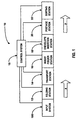
- FIG. 1 a schematic of a typical document inserting system, generally designated 10, which implements the present invention input system 100.
- FIG. 1 a schematic of a typical document inserting system, generally designated 10, which implements the present invention input system 100.
- numerous paper handling stations implemented in inserter system 10 are set forth to provide a thorough understanding of the operating environment of the present invention. However it will become apparent to one skilled in the art that the present invention may be practiced without the specific details in regards to each of these paper-handling stations.
- system 10 preferably includes an input system 100 that feeds paper sheets from a paper web to an accumulating station that accumulates the sheets of paper in collation packets.
- the control document Preferably, only a single sheet of a collation is coded (the control document), which coded information enables the control system 15 of inserter system 10 to control the processing of documents in the various stations of the mass mailing inserter system.
- the code can comprise a bar code, UPC code or the like.
- input system 100 feeds sheets in a paper path, as indicated by arrow "a,” along what is commonly termed the “main deck” of inserter system 10.
- the collations are folded in folding station 12 and the folded collations are then conveyed to a transport station 14, preferably operative to perform buffering operations for maintaining a proper timing scheme for the processing of documents in inserting system 10.
- inserter system 10 includes a control system 15 coupled to each modular component of inserter system 10, which control system 15 controls and harmonizes operation of the various modular components implemented in inserter system 10.
- control system 15 uses an Optical Character Reader (OCR) for reading the code from each coded document.
- OCR Optical Character Reader
- Such a control system is well known in the art and since it forms no part of the present invention, it is not described in detail in order not to obscure the present invention.
- OCR Optical Character Reader
- inserter system 10 implementing the present invention input system 118 is only to be understood as an example configuration of such an inserter system 10. It is of course to be understood that such an inserter system may have many other configurations in accordance with a specific user's needs.
- insert system 100 consists of a paper supply 102, a center-slitting device 106, a merging device 110, a web separating device 114, a stacking and re-feed device 118, a collating device 600 and an accumulating device 700.
- paper supply device 102 it is to be understood to encompass any known device for supplying side-by-side sheets from a paper web 104 to input system 118 (i.e., enabling a two-up format). Paper supply device 102 may feed the side-by-side web 104 from a web roll, which is well known in the art.
- a web separating device 114 is coupled to merging device 110 and is operative to preferably cut the "two-up" A/B web 112 into separated “two-up” (A/B) individual sheets A1/B1, A2/B2, A3/B3, etc.
- web separating device 114 includes either a rotary or guillotine type cutting blade, which cuts the two sheets A and B atop one another 116 every cutter cycle.
- the "two-up" (A/B) sheets 116 are fed from the separating device 114 with a predetermined gap G1 between each succession of "two-up" (A/B) collations 116 conveying downstream from the separating device 114. It is to be appreciated that in order to maintain a high cycle speed for inserter system 10, the aforesaid "two-up" (A/B) web 112 is continually transported into separating device 114 at a constant velocity.
- a stacking and re-feed device 118 is coupled in proximity and downstream to separating device 114 and is operative to separate the "two-up" (A/B) sheet collations 116 into individual sheets (A) and (B).
- Stacking and re-feed device 118 is needed since the "two-up" (A/B) web 112 is merged before being cut into individual sheets and it is necessary to separate the two-up sheets 116 into individual sheets (A) and (B) prior to further downstream processing in inserter system 10.
- the two-up sheets 116 (A and B) are separated from one another by stacking the aforesaid "two-up" (A/B) sheet collations 116 atop of one another in a stacking pile 120.
- stacking and re-feed device 118 enables inserter system 10 to maintain a high cycle speed. That is, in order for inserter system 10 to maintain a high cycle speed (e.g., approximately 18,000 mailpieces per hour) it is essential for the input 100 of inserter system 10 to have a considerably greater cycle speed (e.g., approximately 72,000 sheets per hour) due to resulting time requirements needed for subsequent downstream processing (e.g., collating, accumulating, folding, etc).
- stacking and re-feed device 118 enables sheets to be fed in the aforesaid two-up format 116 from a web roll at an approximately constant speed (e.g., 36,000 cuts per hour) which is also advantageous in that it is difficult to control to the rotational speed of a large web roll (especially at high speeds) for feeding sheets therefrom due to the large inertia forces present upon the web roll.
- the individual sheets 122, (A, B) are then individually fed from stack 120 at a second speed (e.g., over 250 inches per second), which second speed is greater than the input speed (e.g., approximately 117 inches per second).
- Coupled to the output of the stacking and re-feed device 118 is a collating device 600 for shingulating 129 the individually sheets 122 being fed from the stacking/refeed device 118 wherein the individual sheets 122 are fed in seriatim into the collating device 600 and are output therefrom preferably in an shingled formed wherein the individual fed sheets are at least partial overlapped with respect to one another, as shown at 129.
- the collating device 600 and its method of operation will be described further below.
- Coupled downstream of the shingulator device 600 is preferably an accumulator 700 for accumulating the shingled collations 129 fed from the collating device 600.
- the accumulator 700 is operational to collect one or more shingled collations 129 from the collating device 600 into an accumulation 131, which accumulation is preferably edge aligned (i.e., it forms a sheet stack wherein all the sheets of the collected accumulation have their respective edged alighted with one another).
- the collected sheet accumulation 131 is then fed from the accumulation device 700 to a downstream device (i.e., folder 12) for further processing.
- Each collation packet 128 may then be folded, stitched or subsequently combined with other output from document feedings devices located downstream thereof and ultimately inserted into an envelope.
- the collating device 600 described further below is the interoperability of the collating device 600 with the accumulation device 700.
- an advantage of the present invention mass mailing input system 100 is that it: 1) center slits a web before cuffing the web 108 into individual sheets 116; 2) feeds individual sheets 116 at a high speed in a two-up format to a stacking pile 120; feeds individual sheets 122 (A, B) in seriatim in a one-up format from the stacking pile 120 and 4) forms and feeds a controlled shingled sheet collation to an accumulator for enabling high speed sheet accumulations for subsequent processing in the high speed inserter system 10.
- this system arrangement is particularly advantageous in high-speed inserter systems where it is imperative to provide input sheets at high cycle speeds.
- the present invention input system 100 is advantageous in that it eliminates the need for a merging device downstream of the cutting device that results in an additional operation and time.
- the stacking of individual sheets in stacking and re-feed device 118 acts as a buffer between the accumulating devices 600 and 700 and the paper supply 102 and provides quick response times to a feed and gap request from the control system 15 while enabling the paper supply 102 to provide a constant feed of documents.
- FIG. 3 there is shown an input system designated generally by reference numeral 200 that is substantial similar to the above described input system 100, wherein like reference numerals identify like objects.
- stacking and re-feed device 218 of input system 200 is also configured as a "right-angle-turner.” That is, stacking and re-feed device 218 changes the direction of travel for sheets 216 feeding from separating device 114 by 90° relative to sheets feeding from stacking and re-feed device 218.
- the sheet feeder 118 shown in Fig. 4 includes a base frame having opposing side portions 302 and 304.
- a planar deck surface 306 is positioned and supported intermediate the base side portions 302 and 304.
- On the deck surface 306 are positioned two sheet guide rails 308, 310 that extend parallel to each other and are preferably displaceable transversely relative to each other by known means.
- An open slot 312 is formed on the deck 306 in which a pneumatic cylinder assembly 314 is mounted for rotation within and below a stripper plate 316 extending generally parallel with the cylinder assembly 314.
- the stripper blade 316 allows only one sheet to be fed at a time by creating a feed gap relative to the outer circumference of the feed drum 402, which feed gap is approximately equal to the thickness of a sheet to be fed from a sheet stack.
- the lower geometry of the stripper blade 316 is triangular wherein the lower triangular vertex 317 of the stripper blade 316 is approximately located at the center portion of the sheets disposed on the deck 306 as well as the center of the rotating feed drum 402.
- the center portion of the feed drum 402 is provided with a recessed portion 471 preferably in a triangular configuration dimensioned to accommodate the lower triangular vertex 317 of the stripper blade 316.
- the stripper blade 316 is positioned such that its lower triangular vertex 317 resides slightly above the recessed portion 471 of the feed drum 402 and is preferably separated therefrom at a distance substantially equal to the thickness of a sheet to be fed from a sheet stack residing on the feed deck 306 of the sheet feeder 118.
- the metal band 410 is preferably located in the lower vertex of the recessed portion 471 formed in the outer circumference of the feed drum 402.
- the mounting block 322 extends from upper and lower mounting shafts 324 and 326, wherein the lower shaft 326 extends through the mounting block 322 and has it opposing ends affixed respectively in pivoting arm members 328 and 330 (Fig. 4).
- Each pivoting arm member 328 and 330 has a respective end mounted to each side portion 302 and 304 of feeder 118 about a pivoting shaft 342.
- the other end of each pivoting arm member 328 and 330 has a respective swing arm 344, 346 pivotally connected thereto, wherein the pivot point of each swing arm 344, 346 is about the respective ends of upper shaft 324, which shaft 324 also extends through the mounting bock 322.
- a handle shaft 348 extends between the upper ends of the swing arms 344 and 346, wherein a handle member 350 is mounted on an intermediate portion of the handle shaft 348.
- the mounting block 322 is caused to pivot upward and away from the deck 306 as is shown in Fig. 8a.
- the stripper blade 316 moves along a radial path (as indicated by arrow "z") so as not to intersect with the sheet stack 600 disposed on the deck 306 of the sheet feeder 118. This is particularly advantageous because when the mounting block 322 is caused to be moved to its open position (Fig. 8a), the sheet stack disposed on the feed deck need not be interrupted.
- the spring shaft 357 extends through a grooved cutout 361 formed in a side portion 304 of the sheet feeder 118 wherein the other end of the spring shaft 357 extends from one of the pivoting arm members 328.
- the upwardly biasing force of the spring bar 359 causes the swing arms 328 to move upward, which in turn causes the mounting block 322 to pivot upward and away from the deck 306 as is shown in Fig. 8a due to the biasing force of the spring bar 359.
- the mounting block 322 pivots upward and away from the deck 306, and in particular the vacuum drum assembly 314 so as to provide access to the outer surface portion of the outer drum 338 for maintenance and jam access clearance purposes.
- this is effected by having the operator pivot the handle portion 350, about shaft 324, towards the deck 306 (in the direction of arrow "b" in Fig. 8a), which in turn causes the pivoting arm members 328 and 330 to pivot upward about respective shafts 342, which in turn causes corresponding upward pivoting movement of the mounting block 322 away from the deck 306 of the sheet feeder 118.
- sheet feeder 118 is provided with a positive drive nip assembly 451 located downstream of the takeaway nips 338 and preferably in-line with the center axis of the takeaway deck 307 (which corresponds to the center of the feed drum 402).
- the drive nip assembly 451 includes an idler roller 453 extending from the bottom portion of the mounting block 322 which provides a normal force against a continuously running drive belt 455 extending from a cutout provided in the takeaway deck 307.
- the drive belt 455 wraps around a first pulley 457 rotatably mounted below the takeaway deck 307 and a second pulley 459 mounted within the sheet feeder 118.
- the feed drum 402 it is preferably provided with a plurality of radial aligned suction openings 416 arranged in rows.
- the outer surface of the feed drum 402 is preferably coated with a material suitable for gripping sheets of paper such as Mearthane.
- the outer surface of the feed drum 402 is mounted in manner so as to be spaced from the lower vertex 317 of the stripper plate 316 by a thickness corresponding to the individual thickness of the sheets.
- the feed drum 402 is continuously rotating in a clockwise direction relative to the stripper blade 316.
- the feed drum 402 rotates at a speed sufficient to feed at least twenty (20) sheets a second from a sheet stack disposed on the deck 306 of feeder 118.
- the vacuum drum vane 418 is fixedly mounted relative to the feed drum 402 and is provided with an elongate cutout 420 formed along its longitudinal axis.
- the drum vane 418 is fixedly mounted such that its elongate cutout 420 faces the suction openings 416 provided on the feed drum 402 preferably at a region below the lower vertex 317 of the stripper blade 316 (Fig. 7) so as to draw air downward (as indicated by arrow "c" in Figs. 11 and 12) through the suction openings 416 when a vacuum is applied to the elongate cutout 420 as discussed further below.
- valve drum 430 Slideably received within the fixed drum vane 418 is a hollowed valve drum 430, which is provided with an elongate cutout portion 432 along its outer surface. Valve drum 430 also has an open end 434.
- the valve drum 430 is mounted for rotation within the fixed drum vane 418, which controlled rotation is caused by its connection to an electric motor 414 mounted on a side portion 304 of the sheet feeder 118.
- Electric motor 414 is connected to the control system 15 of the inserter system 10, which control system 15 controls activation of the electric motor 414 in accordance with a "mail run job" as programmed in the control system 15 as will be further discussed below.
- the lowermost sheet of the stack 601 is caused to adhere onto the rotating feed drum 402, convey underneath the lower vertex 317 of the stripper plate 316, into the takeaway nips 438 and then positive drive nip assembly 451, and past the sensor 360, so as to be individual feed from the sheet feeder 118 and preferably into a coupled downstream device, such as an accumulator and/or folder 12.
- a coupled downstream device such as an accumulator and/or folder 12.
- the valve drum 430 is caused to be rotated to its default position (Figs. 9 and 10)
- the feeding of sheets from the stack 601 is immediately ceased until once again the valve drum 430 is caused to be rotated to its actuated position (Figs. 11 and 12).
- the interaction between the sensor switch 360 with the control system 15 that enables the control of the sheet feeder 118. That is, when motor 414 is caused to be energized so as to rotate the valve drum 430 to its actuated position to facilitate the feeding of sheets, as mentioned above. Since the "mail run job" of the control system 15 knows the sheet collation number of every mailpiece to be processed by the inserter system 10, it is thus enabled to control the sheet feeder 118 to feed precisely the number of individual sheets for each collation corresponding to each mailpiece to be processed.
- the motor 414 is then caused to be energized, via control system 15, so as to rotate the valve drum to its actuated position (Fig. 11) for an amount of time to cause the feeding of two sheets from the sheet feeder 118, after which the motor 414 is actuated again, via control system 15, so as to rotate the valve drum 430 to its default position (Figs. 9 and 10) preventing the feeding of sheets.
- the sensor switch 360 detects when sheets are fed from the sheet feeder 118, which detection is transmitted to the control system 15 to facilitate its control of the sheet feeder 118.
- control system 15 causes to valve drum 430 to be again maintained in its actuated position for an amount of time to enable the feeding of four sheets, after which the above process is repeated with respect to each succeeding sheet collation number for each succeeding mailpiece to be processed in the inserter system 10.
- a predefined space (as indicated by arrow "x") is caused to be present between the trailing edge 500 of the last sheet 502 of a proceeding collation 504 and the lead edge 506 of the first sheet 508 of a succeeding collation 510. It is also noted that there is a predefined space (as indicated by arrow "y") between the trailing and leading edges of the sheets comprising each collation. It is to be appreciated that after the sheets are fed from the sheet feeder 118, they are then preferably conveyed the collating device 600 as will be described below.
- the spacing between the trailing edge 500 of the last sheet 502 of a proceeding collation 504 and the lead edge 506 of the first sheet 508 of a succeeding collation 510 is significant in that the shingulating device 600 facilitates the operation of providing it with sufficient time to enable the formation and feeding of a shingled document collation made up of a predetermined number of sheets, as will be described further below.
- a sheet feeder 118 having a high-speed pneumatic vacuum assembly for feeding sheets from a stack disposed on a feed deck has been described.
- the collating device 600 coupled to the output of the stacking/refeed device 118.
- overlapping of a sheet on top of another can be partial as shown (e.g., like shingles on a roof-top) or rather can be stacked up atop one another such that the edge of each sheet aligns evenly with the respective edges of the other sheets in the stack.
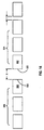
- Fig. 16 illustrates the principle of shingled sheet accumulation, according to collating device 600.
- the first three paths are denoted by P1, P2 and P3, with the path length of path P1 being shorter than P2, P2 being shorter than P3, and so on.
- a controlling means for opening and closing the path so that only one sheet in a stack in an impending accumulation is allowed to travel through the path. For example, in accumulating three sheets, the first sheet entering the entry point 612 will be caused to travel path P3 by keeping C1 and C2 in the closing position while C3 is in the opening position, as shown in Fig. 16.
- the next entering sheet will be caused to travel path P2 by keeping C1 in the closing position and C2 in the opening position. It is followed that C1 is kept in the opening position to allow the last sheet to travel along path P1.
- the path length difference between two adjacent paths shown in Fig. 16 is given by 2Y. If the length of the sheets is L, then the path length difference 2Y should be smaller than L so that the sheets are only partially overlapped with each other. But 2Y can also be equal to the sheet length L so as to allow the sheets in the impending accumulation to exit the accumulator concurrently. Moreover, it is also plausible that 2Y is greater than the sheet length L.
- the number of provided path in an accumulator is fixed, but the number of sheets in each stack can be varied.
- the accumulator includes a sensing device 613 to determine the number of sheets in an impending accumulation. The sensing device can be located behind or in front of the entry point 612.
- the collating device 600 also includes power driven rollers 618 and 638, belts 622 and 634, a number of other rollers 624, 626 and 632 to guide the sheets through the collating device 600. It should be noted that the gaps between the turn-bars 620 and the belts 622 and 624 are greatly exaggerated to show the traveling paths.
- Figs. 18a and 18b show the preferred mechanism for controlling the flipper 630 associated with each path.
- the opening and closing of flipper 630 is caused by the action of a push rod 642 which is linked to the flipper by a lever 640.
- flipper 630 is in a closed position, blocking a sheet from passing through the path associated with the flipper.
- push rod 642 is shown to be pushed upward to cause flipper 630 to move inward (its open position), allowing a sheet to pass through the path.
- the movement of push rod 642 is preferably caused by a pneumatic solenoid 644, an electrical solenoid, an electric rotary actuator or another actuator type mechanism.
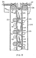
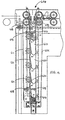
- Fig. 19 illustrates a cross sectional view of collating device 600, according to a preferred embodiment.
- a group of five turn-bars 620 being positioned one atop another to define five different paths, P1 to P5.
- the longest path, or P5 is defined by the lowest turn-bar and a terminating bar 646.
- Each of the top four turn-bars has a flipper 630 to open or close the path associated with the turn-bar.
- Shingulating device 600 also preferably includes a number of optical sensors, each to a turn-bar to sense the passage of the sheets. Only two optical sensors are shown in Fig. 19, denoted by reference numeral 648.
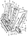
- Fig. 20 illustrates another view of collating device 600, according to a preferred embodiment.
- the collating device 600 has two pivotable wings 650 and 652 for installing guiding rollers and belts.
- the wings 650 and 652 can be opened and separated from the turn-bars 620.
- wing 650 is closed, a plurality of rollers 624 will push the belt 622 against each of the turn-bars 620 to create a paper path substantially conforming to the surface of the turn-bar 620 as shown.
- a flipper 630 is caused to move inward to open a path, a sheet encountering an opened path will be guided through the path under the respective turn-bar 620.
- wing 652 As wing 652 is in the open position, the mechanism that controls the flippers 630 can be seen. As shown in Fig. 20, a number of solenoids 644, push rods 642 and levers 640 are used to control the movement of flippers 630.
- reference numeral 654 denotes a plurality of connectors to the optical sensors 648 shown in Fig. 19.
- Reference numeral 656 denotes a plurality of holding shafts which are part of each wing 650 and 652 construction.
- Fig. 21 illustrates another view of the preferred embodiment, showing the pneumatic manifold connecting solenoids 644 to a pneumatic controller unit 660. Also shown in Fig. 21 are a motor 662, a pulley system 664 and driving belts 666, 668 to drive rollers 618 and 638. With rollers 618 and 638 being driven by the same motor, sheets enter and exit the shingulating device 600 at the same speed. However, it is preferred that roller 638 runs slightly faster than roller 618 to increase the operational efficiency. Moreover, solenoids 644 can be replaced by electric rotary actuators to control the flippers 630.
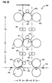
- Fig. 22 illustrates an alternative embodiment of the collating device.
- the collating device 601 in Fig. 22 is constructed as a vertical "tower" to achieve a small footprint.
- a plurality of rollers 670 and 672 are used to guide a plurality of cut sheets, serially and separately entering an entry point 612, to move through different paths P1, P2, P3, ... and to exit at an exiting point 614.
- the opening and closing of the paths are controlled by flippers F1, F2, F3, ... If flipper F1 is in an opening position, a sheet entering the entry point will travel along path P1 to the exiting point.
- the path length difference between two adjacent paths is determined by the spacings Y1, Y2 between rollers, and the radius R of rollers 670 as shown. It is understood that while it is shown in Fig. 22 that all rollers 670 are of the same size, it is not necessarily so.
Landscapes
- Engineering & Computer Science (AREA)
- Mechanical Engineering (AREA)
- Collation Of Sheets And Webs (AREA)
- Forming Counted Batches (AREA)
Abstract
Description
Claims (20)
- A method for supplying document accumulation sets to an inserter system comprising the steps of:supplying sheets to a sheet stacking device;stacking the sheets in a stacking pile;feeding from the stacking pile individual sheets;collating a predetermined number of the individual cut sheets into a collation set;accumulating at least one collation set to form an accumulation set; andfeeding the accumulation set to the inserter system.
- A method for supplying document accumulation sets to an inserter system as recited in claim 1, wherein the step of supplying sheets includes the step of supplying sheets separated from a continuos web.
- A method for supplying document accumulation sets to an inserter system as recited in claim 1 or 2, wherein the step of feeding from the stacking pile includes the step of controlling the rate at which individual sheets are fed from the stacking pile whereby sheets which are to form a said collation set are separated a first predetermined distance from one another and a last sheet of said collation set is separated a second predetermined distance from a succeeding sheet belonging to a succeeding collation set.
- A method for supplying document accumulation sets to an inserter system as recited in any one of the claims 1 to 3, wherein the step of feeding from the stacking pile includes the step of supplying bottommost sheets from the stacking pile.
- A method for supplying document accumulation sets to an inserter system as recited in any one of the claims 1 to 4, wherein the step of collating a predetermined number of the individual cut sheets includes the step of providing a shingled collation set wherein the sheets belonging to a collation set are at least partial overlapping with respect to each succeeding sheet in the collation set.
- A method for supplying document accumulation sets to an inserter system as recited in any one of the claims 1 to 5, wherein the step of accumulating at least one collation set includes the step of providing an accumulation set wherein the respective edges of the sheets belonging to an accumulation set are aligned with respect to one another.
- A method for supplying document accumulation sets to an inserter system as recited in any one of the claims 1 to 6, wherein the step of feeding the accumulation set includes the step of feeding the accumulation set to a document folding device.
- A method for supplying document accumulation sets to an inserter system comprising the steps of:supplying sheets to a sheet stacking device;stacking the sheets in a stacking pile;feeding from the stacking pile individual sheets;providing a plurality of paths connecting an entry point to and an exiting path, each path having a different path length;controlling the paths so as to allow each individual sheet fed from the stacking pile which is to belong to a collation set to travel a different path such that a sheet succeeding a preceding sheet of the collation set entering the entry point travels a different length path than the preceding sheet such that a collation set of a predetermined number of sheets is fed from the exiting point;accumulating at least one collation set to form an accumulation set; andfeeding the accumulation set to the inserter system.
- A method for supplying document accumulation sets to an inserter system as recited in claim 8 wherein the supplying step includes the steps of:supplying a paper web having at least two portions in side-by-side relationship; merging the at least two portions of the web from side-by-side relationship to a substantially upper-lower relationship; andseparating the upper-lower relationship paper web into individual sheets disposed atop one another.
- A method for supplying document accumulation sets to an inserter system as recited in claim 9 wherein the feeding step includes the steps of feeding from the stacking pile individual sheets wherein the individual sheets are fed in groups consisting of one or more sheets whereby each sheet in a group is in seriatim with one another and is separated from one another by a first predetermined distance.
- A method for supplying document accumulation sets to an inserter system as recited in claim 10 wherein the controlling the paths step includes the step of collating a predetermined number of the individual sheets for providing a shingled collation set wherein the sheets belonging to a collation set are at least partial overlapping with respect to each succeeding sheet in the collation set.
- A method for supplying document accumulation sets to an inserter system as recited in claim 11 wherein the step of accumulating at least one collation set includes the step of providing an accumulation set wherein the respective edges of the cut sheets belonging to an accumulation set are aligned with respect to one another.
- A system for supplying document accumulation sets to an inserter system comprising:a sheet supplying device operative to supply sheets;a sheet stacking device operative to receive the sheets from the sheet supplying device and stack the sheets into a sheet pile and subsequently feed individual sheets from the sheet pile;a collating device operative to receive the individual sheets from the sheet stacking device and collate a predetermined number of sheets into a collation set and subsequently feed the collation set from the sheet stacking device;an accumulating device operative to receive at least one collation set from the collating device to provide an accumulation set consisting of the at least one collation set and feed the accumulation set to an inserter system.
- A system for supplying document accumulation sets to an inserter system as recited in claim 13 wherein the collating device further includes providing a plurality of paths connecting an entry point to and an exiting path wherein each path has a different path length and the paths are controlled so as to allow each individual sheet fed from the stacking pile which is to belong to a collation set to travel a different path such that a sheet succeeding a preceding sheet of the collation set entering the entry point travels a different length path than the preceding sheet such that a collation set of a predetermined number of sheets is fed from the exiting point.
- A system for supplying document accumulation sets to an inserter system as recited in claim 14 wherein each of the paths of the collating device are configured to provide at the exiting point a shingled collation set wherein the sheets belonging to a collation set are at least partial overlapping with respect to each succeeding sheet in the collation set.
- A system for supplying document accumulation sets to an inserter system as recited in claim 15 wherein the accumulating device is configured to provide an accumulation set wherein each sheet of each collation set included in the accumulation set is edged aligned with respect to one another.
- A system for supplying document accumulation sets to an inserter system as recited in claim 13 wherein the sheet supplying device includes:a feeding module for supplying a paper web having the two web portions in a side-by-side relationship;a merging module located downstream in the path of travel from the feeding module for feeding the two web portions in upper-lower relationship so as to reorient the paper web from side-by-side to upper-lower relationship; anda separating module located downstream in the path of travel from the merging module for receiving the paper web in the upper-lower relationship and separating the paper web into individual sheets in an upper-lower relationship.
- A system for supplying document accumulation sets to an inserter system as recited in claim 17 wherein the sheet stacking device further includes an upstream side and downstream side and is configured to receive from the upstream side the individual separated sheets in an upper-lower relationship, stack the individual sheets and individually feed one-up sheets from the stack through the downstream side, the stacking module including:a pneumatic assembly mounted in proximity to a sheet feeding end of the stacking module operative to feed individual sheets from the stack, the pneumatic assembly including:an outer rotatably mounted feed drum having an outer and inner circumference and a plurality of suction openings extending between the inner and outer circumferences;an inner vane cylinder having an outer and inner circumference with a vane cutout portion extending between its outer and inner circumference wherein the inner vane cylinder is received within the inner circumference of the feed drum such that the vane cutout portion is in communication with the suction openings of the feed drum; anda rotating inner valve cylinder having an outer and inner circumference with a valve cutout portion extending between its outer and inner circumference rotatably received within the inner vane drum, whereby when the valve cylinder is rotated such that its valve cutout portion is in communication with the vane cutout portion, and a vacuum is applied to the inner circumference of the valve cylinder, air is caused to be suctioned downward through the suction openings of the feed drum so as to cause a sheet on the bottom of the paper stack to adhere against the rotating feed drum and convey away from the sheet stack.
- A system for supplying document accumulation sets to an inserter system as recited in claim 18 wherein the sheet stacking device further includes a sensor located intermediate the feed drum and the sheet feeding end of the sheet stacking device for detecting passage of fed sheets from the sheet stack.
- An inserter system comprising a system for supplying document accumulation sets according to any one of the preceding claims 13 to 19.
Applications Claiming Priority (2)
| Application Number | Priority Date | Filing Date | Title |
|---|---|---|---|
| US09/310,218 US6305680B1 (en) | 1999-05-12 | 1999-05-12 | System and method for providing document accumulation sets to an inserter system |
| US310218 | 1999-05-12 |
Publications (3)
| Publication Number | Publication Date |
|---|---|
| EP1053963A2 true EP1053963A2 (en) | 2000-11-22 |
| EP1053963A3 EP1053963A3 (en) | 2002-04-10 |
| EP1053963B1 EP1053963B1 (en) | 2004-09-22 |
Family
ID=23201490
Family Applications (1)
| Application Number | Title | Priority Date | Filing Date |
|---|---|---|---|
| EP00110152A Expired - Lifetime EP1053963B1 (en) | 1999-05-12 | 2000-05-12 | A system and method for providing document accumulation sets to an inserter system |
Country Status (4)
| Country | Link |
|---|---|
| US (1) | US6305680B1 (en) |
| EP (1) | EP1053963B1 (en) |
| CA (1) | CA2307822C (en) |
| DE (1) | DE60013955T2 (en) |
Cited By (3)
| Publication number | Priority date | Publication date | Assignee | Title |
|---|---|---|---|---|
| EP1227053A3 (en) * | 2001-01-29 | 2004-02-18 | MBO MASCHINENBAU OPPENWEILER BINDER GMBH & CO. | Method and device for forming a correctly sorted pile of folded sheets |
| EP1528020A3 (en) * | 2003-10-30 | 2008-04-02 | Horizon International Inc. | Sheet supplying device |
| US20100251673A1 (en) * | 2009-04-06 | 2010-10-07 | Kern Global Llc | Apparatus and method to control material converting and envelope stuffing |
Families Citing this family (12)
| Publication number | Priority date | Publication date | Assignee | Title |
|---|---|---|---|---|
| US6592114B2 (en) * | 2001-02-06 | 2003-07-15 | Kenneth A. Stevens | Streak free apparatus for processing and stacking printed forms |
| US6615105B2 (en) * | 2001-10-18 | 2003-09-02 | Pitney Bowes Inc. | System and method for adjusting sheet input to an inserter system |
| US6612571B2 (en) | 2001-12-06 | 2003-09-02 | Xerox Corporation | Sheet conveying device having multiple outputs |
| US7344062B2 (en) * | 2002-12-06 | 2008-03-18 | First Data Corporation | Systems for preparing presentation instruments for distribution |
| US6817518B2 (en) * | 2002-12-06 | 2004-11-16 | First Data Corporation | Systems for preparing presentation instruments for distribution |
| US20040156064A1 (en) * | 2003-02-07 | 2004-08-12 | Kevin Owen | Printing methods and apparatus |
| US20050097866A1 (en) * | 2003-11-12 | 2005-05-12 | Solar Communications, Inc. | System and method for producing personalized imaged material |
| US20050099657A1 (en) * | 2003-11-12 | 2005-05-12 | Solar Communications, Inc. | System and method for producing personalized imaged material |
| US20060024106A1 (en) * | 2004-07-27 | 2006-02-02 | Mattern James M | High speed serial printing using meters |
| US20100042252A1 (en) * | 2008-08-13 | 2010-02-18 | Xerox Corporation | Disk type apparatus and corresponding methods |
| US8123223B1 (en) | 2010-10-04 | 2012-02-28 | Andersen & Associates | Document printer and inserter |
| JP7882473B2 (en) * | 2022-03-25 | 2026-06-30 | デュプロ精工株式会社 | Paper sorting device |
Family Cites Families (27)
| Publication number | Priority date | Publication date | Assignee | Title |
|---|---|---|---|---|
| US3983679A (en) * | 1975-05-30 | 1976-10-05 | Bell & Howell Company | Apparatus and method of processing mail |
| US4190241A (en) | 1978-05-01 | 1980-02-26 | Kimberly-Clark Corporation | Apparatus for converting paper rolls into stacks of individual folded paper sheets |
| DE2902068C2 (en) | 1979-01-19 | 1980-12-11 | G.A.O. Gesellschaft Fuer Automation Und Organisation Mbh, 8000 Muenchen | Separation device for flat conveyed goods |
| CH639623A5 (en) | 1979-06-23 | 1983-11-30 | Winkler Duennebier Kg Masch | DEVICE FOR TRANSPORTING AREA PARTS, ESPECIALLY PAPER SHEETS, CARDS, MAIL OR SHIPPING PAPERS. |
| JPS5670886A (en) * | 1979-11-14 | 1981-06-13 | Nippon Electric Co | Sorter |
| US4355795A (en) | 1980-03-04 | 1982-10-26 | Bobst Champlain, Inc. | Sheet handling device |
| US4585113A (en) | 1983-10-05 | 1986-04-29 | R. A. Jones & Co. Inc. | Apparatus for transferring articles |
| DE3447331A1 (en) | 1984-12-24 | 1986-06-26 | Mathias Bäuerle GmbH, 7742 ST. Georgen | PNEUMATIC BOW FEEDER |
| GB8505759D0 (en) | 1985-03-06 | 1985-04-11 | De La Rue Syst | Assembling sheets into stack |
| DE3614623C1 (en) | 1986-04-30 | 1987-10-22 | Baeuerle Gmbh Mathias | Bow feed table with blow nozzles |
| US4905044A (en) | 1986-11-19 | 1990-02-27 | Minolta Camera Kabushiki Kaisha | Document conveying apparatus |
| DE3723259C2 (en) * | 1987-07-14 | 1995-04-13 | Licentia Gmbh | Stacking device for letters |
| US4989853A (en) | 1988-11-28 | 1991-02-05 | Xerox Corporation | Apparatus for offsetting sheets |
| US4989852A (en) * | 1989-02-23 | 1991-02-05 | Gunther International, Ltd. | Electronic publishing system |
| US5087805A (en) * | 1990-07-06 | 1992-02-11 | Webcraft Technologies, Inc. | Printed and encoded mass distributable response piece and method of making the same |
| US4939888A (en) * | 1990-07-06 | 1990-07-10 | Webcraft Technologies, Inc. | Method for producing a mass distributable printed packet |
| US5088717A (en) | 1989-08-12 | 1992-02-18 | Konica Corporation | Paper feeding apparatus having a three cylinder vacuum member |
| US5072922A (en) | 1991-02-25 | 1991-12-17 | Paulson Harold E | Vacuum drum for printing press feeder |
| US5156384A (en) * | 1991-11-04 | 1992-10-20 | Webcraft Technologies, Inc. | Collect tab stacking method with transverse cutting stage forming inserts and indexing inserts |
| NL9200294A (en) * | 1992-02-18 | 1993-09-16 | Hadewe Bv | METHOD FOR COMPOSITION OF A POSTAGE AND SYSTEM AND ALIGNMENT STATION FOR CARRYING OUT THAT METHOD |
| JPH05286619A (en) * | 1992-04-07 | 1993-11-02 | Ricoh Co Ltd | Sheet discharge device of image forming device |
| US5258817A (en) | 1992-07-01 | 1993-11-02 | Xerox Corporation | Document handling system having a shunt path |
| SE9400862L (en) * | 1994-03-15 | 1995-06-26 | Straalfors Ab | Method and apparatus for handling sheets provided with information in a laser printer |
| US5642878A (en) | 1995-05-04 | 1997-07-01 | F. L. Smithe Machine Company, Inc. | Method and apparatus for separating sheets fed from the bottom of a stack |
| US5689795A (en) * | 1996-09-24 | 1997-11-18 | Xerox Corporation | Sheet transfer apparatus with adaptive speed-up delay |
| US5947461A (en) * | 1997-08-25 | 1999-09-07 | Pitney Bowes Inc. | Apparatus and method for collating documents cut from a continuous web |
| US6095513A (en) * | 1998-12-16 | 2000-08-01 | Pitney Bowes Inc. | Hi-speed sheet feeder |
-
1999
- 1999-05-12 US US09/310,218 patent/US6305680B1/en not_active Expired - Fee Related
-
2000
- 2000-05-09 CA CA002307822A patent/CA2307822C/en not_active Expired - Fee Related
- 2000-05-12 EP EP00110152A patent/EP1053963B1/en not_active Expired - Lifetime
- 2000-05-12 DE DE60013955T patent/DE60013955T2/en not_active Expired - Lifetime
Cited By (8)
| Publication number | Priority date | Publication date | Assignee | Title |
|---|---|---|---|---|
| EP1227053A3 (en) * | 2001-01-29 | 2004-02-18 | MBO MASCHINENBAU OPPENWEILER BINDER GMBH & CO. | Method and device for forming a correctly sorted pile of folded sheets |
| EP1528020A3 (en) * | 2003-10-30 | 2008-04-02 | Horizon International Inc. | Sheet supplying device |
| US20100251673A1 (en) * | 2009-04-06 | 2010-10-07 | Kern Global Llc | Apparatus and method to control material converting and envelope stuffing |
| WO2010118020A1 (en) * | 2009-04-06 | 2010-10-14 | Kern Global Llc | Apparatus and method to control material converting and envelope stuffing |
| EP2416970A1 (en) * | 2009-04-06 | 2012-02-15 | Kern Global Llc | Apparatus and method to control material converting and envelope stuffing |
| JP2012522672A (en) * | 2009-04-06 | 2012-09-27 | カーン・グローバル・エルエルシー | Apparatus and method for controlling material processing and envelope packing |
| AU2010234569B2 (en) * | 2009-04-06 | 2015-11-26 | Kern Global Llc | Apparatus and method to control material converting and envelope stuffing |
| US9221295B2 (en) * | 2009-04-06 | 2015-12-29 | Kern Global Llc | Apparatus and method to control material converting and envelope stuffing |
Also Published As
| Publication number | Publication date |
|---|---|
| US6305680B1 (en) | 2001-10-23 |
| DE60013955T2 (en) | 2005-10-06 |
| DE60013955D1 (en) | 2004-10-28 |
| CA2307822C (en) | 2007-03-27 |
| CA2307822A1 (en) | 2000-11-12 |
| EP1053963B1 (en) | 2004-09-22 |
| EP1053963A3 (en) | 2002-04-10 |
Similar Documents
| Publication | Publication Date | Title |
|---|---|---|
| CA2292066C (en) | High speed pneumatic document input system | |
| US6615105B2 (en) | System and method for adjusting sheet input to an inserter system | |
| EP1053963B1 (en) | A system and method for providing document accumulation sets to an inserter system | |
| US6161828A (en) | Sheet collation device and method | |
| US6364305B1 (en) | System and method for providing sheets to an inserter system | |
| CA2246011C (en) | High speed document input system | |
| CA2468210C (en) | System and method for providing sheets to an inserter system using a rotary cutter | |
| EP1108563B1 (en) | Method for supplying envelopes to an inserter system | |
| CA2329599C (en) | System and method for document input control | |
| EP1016604B1 (en) | High-speed sheet feeder | |
| CA2292061C (en) | Hi-speed pneumatic sheet feeder | |
| US7427059B2 (en) | Paper handling system materials exit path arrangement | |
| US6164640A (en) | Apparatus for directionally reorienting sheets | |
| EP1795473B1 (en) | High throughput right angle turn module | |
| EP1067077B1 (en) | Method and device for sheet collation | |
| EP1577242A1 (en) | System and method for providing sheets to an inserter system using a high speed cutter and right angle turn | |
| US6102390A (en) | Separator stone adjustment assembly | |
| CA2472870C (en) | Apparatus and method for accumulating sheets | |
| US20060220296A1 (en) | Paper handling system material feed path arrangement | |
| CA2558631A1 (en) | Apparatus and method for accumulating sheets |
Legal Events
| Date | Code | Title | Description |
|---|---|---|---|
| PUAI | Public reference made under article 153(3) epc to a published international application that has entered the european phase |
Free format text: ORIGINAL CODE: 0009012 |
|
| AK | Designated contracting states |
Kind code of ref document: A2 Designated state(s): AT BE CH CY DE DK ES FI FR GB GR IE IT LI LU MC NL PT SE Kind code of ref document: A2 Designated state(s): DE FR GB |
|
| AX | Request for extension of the european patent |
Free format text: AL;LT;LV;MK;RO;SI |
|
| PUAL | Search report despatched |
Free format text: ORIGINAL CODE: 0009013 |
|
| AK | Designated contracting states |
Kind code of ref document: A3 Designated state(s): AT BE CH CY DE DK ES FI FR GB GR IE IT LI LU MC NL PT SE |
|
| AX | Request for extension of the european patent |
Free format text: AL;LT;LV;MK;RO;SI |
|
| 17P | Request for examination filed |
Effective date: 20021002 |
|
| AKX | Designation fees paid |
Free format text: DE FR GB |
|
| 17Q | First examination report despatched |
Effective date: 20030410 |
|
| GRAP | Despatch of communication of intention to grant a patent |
Free format text: ORIGINAL CODE: EPIDOSNIGR1 |
|
| GRAS | Grant fee paid |
Free format text: ORIGINAL CODE: EPIDOSNIGR3 |
|
| GRAA | (expected) grant |
Free format text: ORIGINAL CODE: 0009210 |
|
| AK | Designated contracting states |
Kind code of ref document: B1 Designated state(s): DE FR GB |
|
| REG | Reference to a national code |
Ref country code: GB Ref legal event code: FG4D |
|
| REG | Reference to a national code |
Ref country code: IE Ref legal event code: FG4D |
|
| REF | Corresponds to: |
Ref document number: 60013955 Country of ref document: DE Date of ref document: 20041028 Kind code of ref document: P |
|
| ET | Fr: translation filed | ||
| PLBE | No opposition filed within time limit |
Free format text: ORIGINAL CODE: 0009261 |
|
| STAA | Information on the status of an ep patent application or granted ep patent |
Free format text: STATUS: NO OPPOSITION FILED WITHIN TIME LIMIT |
|
| 26N | No opposition filed |
Effective date: 20050623 |
|
| PGFP | Annual fee paid to national office [announced via postgrant information from national office to epo] |
Ref country code: FR Payment date: 20090518 Year of fee payment: 10 |
|
| REG | Reference to a national code |
Ref country code: FR Ref legal event code: ST Effective date: 20110131 |
|
| PG25 | Lapsed in a contracting state [announced via postgrant information from national office to epo] |
Ref country code: FR Free format text: LAPSE BECAUSE OF NON-PAYMENT OF DUE FEES Effective date: 20100531 |
|
| PGFP | Annual fee paid to national office [announced via postgrant information from national office to epo] |
Ref country code: GB Payment date: 20140527 Year of fee payment: 15 |
|
| PGFP | Annual fee paid to national office [announced via postgrant information from national office to epo] |
Ref country code: DE Payment date: 20140529 Year of fee payment: 15 |
|
| REG | Reference to a national code |
Ref country code: DE Ref legal event code: R119 Ref document number: 60013955 Country of ref document: DE |
|
| GBPC | Gb: european patent ceased through non-payment of renewal fee |
Effective date: 20150512 |
|
| PG25 | Lapsed in a contracting state [announced via postgrant information from national office to epo] |
Ref country code: GB Free format text: LAPSE BECAUSE OF NON-PAYMENT OF DUE FEES Effective date: 20150512 Ref country code: DE Free format text: LAPSE BECAUSE OF NON-PAYMENT OF DUE FEES Effective date: 20151201 |