EP1053894A1 - System for monitoring the air pressure of vehicle tyres - Google Patents
System for monitoring the air pressure of vehicle tyres Download PDFInfo
- Publication number
- EP1053894A1 EP1053894A1 EP00401380A EP00401380A EP1053894A1 EP 1053894 A1 EP1053894 A1 EP 1053894A1 EP 00401380 A EP00401380 A EP 00401380A EP 00401380 A EP00401380 A EP 00401380A EP 1053894 A1 EP1053894 A1 EP 1053894A1
- Authority
- EP
- European Patent Office
- Prior art keywords
- processor
- pressure
- transmitter
- temperature
- capacitor
- Prior art date
- Legal status (The legal status is an assumption and is not a legal conclusion. Google has not performed a legal analysis and makes no representation as to the accuracy of the status listed.)
- Granted
Links
- 238000012544 monitoring process Methods 0.000 title 1
- 239000003990 capacitor Substances 0.000 claims description 12
- 230000005540 biological transmission Effects 0.000 claims description 11
- 230000004913 activation Effects 0.000 claims description 8
- WHXSMMKQMYFTQS-UHFFFAOYSA-N Lithium Chemical compound [Li] WHXSMMKQMYFTQS-UHFFFAOYSA-N 0.000 description 2
- 238000009530 blood pressure measurement Methods 0.000 description 2
- 229910052744 lithium Inorganic materials 0.000 description 2
- 235000014676 Phragmites communis Nutrition 0.000 description 1
- 238000010586 diagram Methods 0.000 description 1
- 230000002045 lasting effect Effects 0.000 description 1
- 238000005259 measurement Methods 0.000 description 1
- 230000000750 progressive effect Effects 0.000 description 1
- 230000033764 rhythmic process Effects 0.000 description 1
Images

Classifications
-
- B—PERFORMING OPERATIONS; TRANSPORTING
- B60—VEHICLES IN GENERAL
- B60C—VEHICLE TYRES; TYRE INFLATION; TYRE CHANGING; CONNECTING VALVES TO INFLATABLE ELASTIC BODIES IN GENERAL; DEVICES OR ARRANGEMENTS RELATED TO TYRES
- B60C23/00—Devices for measuring, signalling, controlling, or distributing tyre pressure or temperature, specially adapted for mounting on vehicles; Arrangement of tyre inflating devices on vehicles, e.g. of pumps or of tanks; Tyre cooling arrangements
- B60C23/20—Devices for measuring or signalling tyre temperature only
Definitions
- the system must emit a determined number Ne, generally five, of identical bursts and a number Nr of these bursts must have been received for that it is considered that the information of the moment has been issued and received.
- the bursts can be broadcast, to fix ideas, every hour, if the vehicle is stopped, every six minutes, if the vehicle is moving.
- the system is activated at regular intervals, for example every two seconds for the transmission of bursts.
- the bursts, each of duration t b are spaced apart, generally still 12 ms.
- trains of five bursts are emitted, with a duration of 88 ms during an activation period of 2s.
- the processor is arranged to, below a temperature threshold, spread the transmission of bursts from a train over several activation intervals, advantageously, one burst per activation interval.
- a capacitor 11 is mounted in parallel on the battery supply 10 to ensure in particular the supply of the transmitter 3 during transmission periods and to recharge outside of these issue periods.
- Pressure sensor 1 measurements are issued every six minutes when the wheel turns and, if not, every hour.
- An inertia sensor not shown, such as a Reed bulb, controls the processor 2.
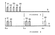
- processor 2 emits two bursts 31, 32 on a first period, two bursts 33, 34 on the following period and a last burst 35 on the third period, memorizing each time these elements to manage the following.
- these bursts have the expected spacing of 12 ms.
Abstract
Description
Un système de contrôle de la pression d'un pneumatique de roue de véhicule comprend au moins, inséré dans la jante de la roue, un capteur de pression, un émetteur et une pile et un condensateur d'alimentation de l'émetteur.A tire tire pressure control system vehicle comprises at least, inserted in the rim of the wheel, a sensor pressure, a transmitter and a battery and a supply capacitor the transmitter.
Le système doit émettre régulièrement vers le calculateur central du véhicule des rafales (bursts) de bits d'informations relatives à la pression du pneumatique, naturellement, mais également, par exemple, à la température, la tension de la pile d'alimentation, l'identification de la roue.The system must transmit regularly to the central computer of the conveys bursts of pressure information bits of the tire, of course, but also, for example, at the temperature, battery voltage, identification of the wheel.
Le système doit émettre un nombre Ne déterminé, généralement cinq, de rafales identiques et un nombre Nr de ces rafales doit avoir été reçu pour qu'il soit considéré que les informations du moment ont bien été émises et reçues. L'émission des rafales peut s'effectuer, pour fixer les idées, toutes les heures, si le véhicule est à l'arrêt, toutes les six minutes, si le véhicule roule.The system must emit a determined number Ne, generally five, of identical bursts and a number Nr of these bursts must have been received for that it is considered that the information of the moment has been issued and received. The bursts can be broadcast, to fix ideas, every hour, if the vehicle is stopped, every six minutes, if the vehicle is moving.
Par ailleurs, le système est activé à intervalles réguliers, par exemple toutes les deux secondes pour l'émission des rafales. Enfin, les rafales, chacun d'une durée tb, généralement de 8 ms, sont espacés, généralement encore de 12 ms. Ainsi, il est émis des trains de cinq rafales, d'une durée de 88 ms pendant une période d'activation de 2s.Furthermore, the system is activated at regular intervals, for example every two seconds for the transmission of bursts. Finally, the bursts, each of duration t b , generally 8 ms, are spaced apart, generally still 12 ms. Thus, trains of five bursts are emitted, with a duration of 88 ms during an activation period of 2s.
Si l'on veut que le système résiste à des températures très basses, de l'ordre de -40°C, il faut utiliser des piles d'alimentation d'un coût élevé, de l'ordre de 2 Euros.If you want the system to withstand very low temperatures, in the range of -40 ° C, it is necessary to use high-cost power batteries, around 2 Euros.
La demanderesse a cherché à s'affranchir de cette contrainte en utilisant des piles bon marché, d'un coût inférieur à 1 Euro, mais qui, par conséquent, ne sont pas faites pour des températures aussi basses, comme par exemple des piles au lithium recyclables. The plaintiff sought to overcome this constraint by using inexpensive batteries, costing less than 1 Euro, but which, for therefore, are not made for such low temperatures, as for example recyclable lithium batteries.
A cet effet, l'invention concerne un système de contrôle de la pression d'un pneumatique d'une roue de véhicule comprenant
- un capteur de pression,
- un émetteur d'émission de données de pression
- une pile d'alimentation,
- un capteur de température et
- un processeur,
- a pressure sensor,
- a pressure data transmitter
- a battery,
- a temperature sensor and
- a processor,
De préférence, un condensateur est monté en parallèle sur la pile d'alimentation pour assurer l'alimentation de l'émetteur pendant les périodes d'émission et pour se recharger hors de ces périodes d'émission.Preferably, a capacitor is mounted in parallel on the battery to supply the transmitter with power during emission periods and to recharge outside of these emission periods.
De préférence encore, les données de pression étant émises par trains de rafales identiques et le système étant activé à intervalles réguliers, le processeur est agencé pour, en deça d'un seuil de température, étaler l'émission des rafales d'un train sur plusieurs intervalles d'activation, avantageusement, une rafale par intervalle d'activation.More preferably still, the pressure data being emitted by trains of identical gusts and the system being activated at regular intervals, the processor is arranged to, below a temperature threshold, spread the transmission of bursts from a train over several activation intervals, advantageously, one burst per activation interval.
Aux basses températures, la résistance de la pile augmente considérablement et l'étalement de l'émission des rafales laisse entre deux rafales plus de temps à la pile pour recharger le condensateur.At low temperatures, the resistance of the battery increases considerably and the spread of the burst emission leaves between two longer bursts to the battery to recharge the capacitor.
Dans la forme de réalisation préférée du système de l'invention, la pile, le condensateur, les capteurs, le processeur et l'émetteur sont montés en parallèle.In the preferred embodiment of the system of the invention, the battery, the capacitor, the sensors, the processor and the transmitter are mounted in parallel.
L'invention sera mieux comprise à l'aide de la description suivante d'une forme de réalisation préférée du système de contrôle de la pression d'un pneumatique de l'invention, en référence au dessin annexé, sur lequel :
- la figure 1 est une représentation schématique du système de contrôle de pression de l'invention, logé dans un pneumatique d'un véhicule automobile dont le calculateur de bord exploite les mesures de pression,
- la figure 2 est un schéma par blocs du système de la figure 1, et
- les figures 3 et 4 illustrent, en fonction de temps t, l'émission de rafales de signaux de télémesure de pression.
- FIG. 1 is a diagrammatic representation of the pressure control system of the invention, housed in a tire of a motor vehicle whose on-board computer uses the pressure measurements,
- FIG. 2 is a block diagram of the system of FIG. 1, and
- Figures 3 and 4 illustrate, as a function of time t, the emission of bursts of pressure telemetry signals.
Le système de contrôle de pression, portant la référence 9 sur la figure 1,
est monté à l'intérieur d'un pneumatique 8 de roue de véhicule, ici une
automobile, et précisément fixé à la valve. Un calculateur de bord 19 du
véhicule reçoit des télémesures de pression émises par le système 9 et les
exploite pour avertir le conducteur de toute anomalie.The pressure control system, bearing the
Comme le montre la figure 2, le système 9 comporte un capteur de
pression 1 commandant un émetteur sans fil 3, ici radio, à travers un
processeur 2 de gestion des émissions de l'émetteur 3 vers le calculateur
de bord 19. Un capteur de température 4 est relié en sortie au processeur
2 pour la gestion des émissions de l'émetteur 3. Une pile 10, ici au
lithium, alimente l'ensemble des circuits 1, 2, 3, 4, qui sont montés en
parallèle, entre une liaison d'alimentation positive et la masse.As shown in Figure 2, the
Dans cet exemple, un condensateur 11 est monté en parallèle sur la pile
d'alimentation 10 pour assurer en particulier l'alimentation de l'émetteur
3 pendant les périodes d'émission et pour se recharger hors de ces
périodes d'émission.In this example, a
Le processeur 2 comporte un circuit de base de temps 20 qui en rythme le
fonctionnement et en particulier commande un circuit 21 de mise en veille
et de réveil des autres circuits du processeur 2, tels qu'un bloc de calcul
(ALU) 22.The
Les figures 3 et 4 illustrent le fonctionnement du système 9.Figures 3 and 4 illustrate the operation of
Les mesures du capteur de pression 1 sont émises toutes les six minutes
lorsque la roue tourne et, sinon, toutes les heures. Un capteur à inertie,
non représenté, tel qu'une ampoule Reed, commande à cet effet le
processeur 2. Pressure sensor 1 measurements are issued every six minutes
when the wheel turns and, if not, every hour. An inertia sensor,
not shown, such as a Reed bulb, controls the
Celui-ci fonctionne avec un cycle élémentaire durant ici 2 secondes, c'est-à-dire
qu'il est en veille, à faible consommation, la plupart du temps et est
réveillé et activé à intervalles réguliers toutes les 2 secondes, par un
temporisateur du circuit 21, pour effectuer une tâche éventuelle dans le
bloc de calcul 22. Le bloc de calcul 22 garde en mémoire les instants des
dernières émissions radio qu'il a commandées, pour déterminer, d'après
l'heure courante, s'il doit effectuer une nouvelle émission, d'un nouveau
train ou d'une nouvelle rafale dans un train.This works with an elementary cycle lasting here 2 seconds, that is to say
that it is in standby, low consumption, most of the time and is
awakened and activated at regular intervals every 2 seconds, by a
timer of
Une mesure de pression du capteur 1 est numérisée et mémorisée dans le
processeur 2 et émise par radio par un train de cinq rafales identiques de
données de pression, pour garantir sa transmission. Chaque rafale dure ici
8 ms. En fonctionnement classique (figure 3), au-dessus d'un seuil bas, ici
-20°C, les rafales 21, 22, 23, 24, 25 sont espacées de 12 ms et toutes
émises en début d'une même période d'activation de 2 secondes.A pressure measurement from sensor 1 is digitized and stored in the
Au-dessus de -20°C, la pile 10 présente une résistance interne limitée à
quelques ohms, qui permet d'alimenter suffisamment l'émetteur 3. Le
condensateur réservoir 11, de quelques centaines de µFarad et de
quelques ohms de résistance série, contribue à stabiliser la tension
d'alimentation mais n'a alors qu'un rôle annexe puisque la pile 10 est
aussi à faible résistance.Above -20 ° C., the
Par contre, si la température tombe en-dessous du seuil de -20°C, la
résistance de la pile 10 s'accroít très nettement, pour atteindre une
centaine d'ohms à -40°C. Le condensateur 11 conserve par contre
sensiblement ses caractéristiques à cette température.However, if the temperature falls below the -20 ° C threshold, the
resistance of the
En deça du seuil de -20°C, la résistance série de la pile 10 est trop élevée
pour fournir, sous la tension prévue, le courant de l'émetteur 3 lorsqu'il
est actif. Afin de cependant permettre le fonctionnement de celui-ci, le
processeur 2 commande l'émission des données de pression en fonction
de la température, c'est-à-dire qu'il étale dans le temps les émissions.
Plus précisément, en deça du seuil de -20°C, il étale l'émission des
rafales d'un train sur plusieurs des intervalles d'activation de 2 secondes. Below the threshold of -20 ° C, the series resistance of
Dans cet exemple, cet étalement est progressif en fonction de la baisse de la température.In this example, this spreading is progressive as a function of the fall in temperature.
Dans le cas de la figure 4, pour lequel le capteur de température 4 indique
-30°C, le processeur 2 émet deux rafales 31, 32 sur une première
période, deux rafales 33, 34 sur la période suivante et une dernière rafale
35 sur la troisième période, en mémorisant à chaque fois ces éléments
pour gérer les suivants.In the case of FIG. 4, for which the
Dans cet exemple, en cas de pluralité de rafales 31, 32 par période, ces
rafales ont l'espacement prévu de 12 ms.In this example, in the event of a plurality of
Si la température descend à -40°C par exemple, le processeur 2 ralentit
encore le rythme moyen d'émission des rafales 31-35 en commandant
l'émission d'une seule rafale par intervalle d'activation. En deça du seuil
de -20°C, le condensateur 11 a un rôle principal dans la fourniture de
l'énergie d'alimentation électrique dans de bonnes conditions de stabilité
de tension, en particulier à l'émetteur 3 qui présente une consommation
élevée lorsqu'il émet. Cette fourniture s'effectue en effet sous basse
impédance (résistance). Le condensateur 11 se décharge partiellement
lorsque l'émetteur 3 émet les données mais l'émission du train
d'impulsions 31-35 est suffisamment étalée pour que le condensateur 11
soit suffisamment rechargé par la pile 10 lorsque l'émetteur 3 est à
nouveau activé. Il peut d'ailleurs être prévu que les périodes dans
lesquelles est émise une rafale soient séparées par des périodes inactives.
L'ensemble pile 10 - condensateur-intégrateur 11, ainsi sollicité peu
souvent, peut fournir une puissance instantanée élevée et équivaut à une
pile de prix élevé qui conserverait une faible résistance à très basse
température.If the temperature drops to -40 ° C for example,
Claims (5)
l'émission des données de pression est commandée par le processeur (2) en fonction de la température, en-deça d'un seuil de température prédéterminé.Tire pressure control system for a vehicle wheel comprising
the transmission of the pressure data is controlled by the processor (2) as a function of the temperature, below a predetermined temperature threshold.
Applications Claiming Priority (2)
| Application Number | Priority Date | Filing Date | Title |
|---|---|---|---|
| FR9906396 | 1999-05-20 | ||
| FR9906396A FR2793879B1 (en) | 1999-05-20 | 1999-05-20 | TIRE PRESSURE MONITORING SYSTEM |
Publications (2)
| Publication Number | Publication Date |
|---|---|
| EP1053894A1 true EP1053894A1 (en) | 2000-11-22 |
| EP1053894B1 EP1053894B1 (en) | 2005-06-15 |
Family
ID=9545796
Family Applications (1)
| Application Number | Title | Priority Date | Filing Date |
|---|---|---|---|
| EP00401380A Expired - Lifetime EP1053894B1 (en) | 1999-05-20 | 2000-05-19 | System for monitoring the air pressure of vehicle tyres |
Country Status (6)
| Country | Link |
|---|---|
| US (1) | US6218937B1 (en) |
| EP (1) | EP1053894B1 (en) |
| JP (1) | JP4472836B2 (en) |
| DE (1) | DE60020774T2 (en) |
| ES (1) | ES2243217T3 (en) |
| FR (1) | FR2793879B1 (en) |
Cited By (2)
| Publication number | Priority date | Publication date | Assignee | Title |
|---|---|---|---|---|
| CN102712227A (en) * | 2010-01-15 | 2012-10-03 | 约翰逊控制技术公司 | Method for exchanging signals between a tire pressure sensor and a central processing unit in a motor vehicle |
| CN105034716A (en) * | 2015-07-09 | 2015-11-11 | 特拓(青岛)轮胎技术有限公司 | Tyre internal temperature and pressure detection device and detection method |
Families Citing this family (17)
| Publication number | Priority date | Publication date | Assignee | Title |
|---|---|---|---|---|
| US7161476B2 (en) | 2000-07-26 | 2007-01-09 | Bridgestone Firestone North American Tire, Llc | Electronic tire management system |
| US8266465B2 (en) | 2000-07-26 | 2012-09-11 | Bridgestone Americas Tire Operation, LLC | System for conserving battery life in a battery operated device |
| US20030058118A1 (en) * | 2001-05-15 | 2003-03-27 | Wilson Kitchener C. | Vehicle and vehicle tire monitoring system, apparatus and method |
| KR20020073326A (en) * | 2002-09-06 | 2002-09-23 | 이영태 | Device for monitoring pressure of tire in vehicles |
| FR2844748B1 (en) * | 2002-09-25 | 2004-11-26 | Johnson Contr Automotive Elect | TIRE PRESSURE MONITORING SYSTEM FOR A MOTOR VEHICLE |
| JP2004258992A (en) * | 2003-02-26 | 2004-09-16 | Pacific Ind Co Ltd | Tire condition monitoring device and transmitter thereof |
| JP2004312509A (en) * | 2003-04-09 | 2004-11-04 | Matsushita Electric Ind Co Ltd | Wireless communication apparatus |
| DE10323631A1 (en) * | 2003-05-20 | 2004-12-16 | Beru Ag | Device for monitoring and wireless signaling of a pressure or a change in pressure in pneumatic tires on vehicles |
| FR2863205B1 (en) * | 2003-12-08 | 2006-02-17 | Michelin Soc Tech | PNEUMATIC INFLATION METHOD, DEVICE AND MACHINE FOR IMPLEMENTING THE METHOD |
| DE102004001658B4 (en) * | 2004-01-12 | 2006-05-04 | Infineon Technologies Ag | Wireless tire pressure sensor and method of operating a wireless tire pressure sensor |
| JP4386773B2 (en) * | 2004-03-22 | 2009-12-16 | 横浜ゴム株式会社 | Tire side mounted electronic device |
| DE502004009736D1 (en) * | 2004-04-01 | 2009-08-20 | Conti Temic Microelectronic | METHOD AND DEVICE FOR TRANSMISSION BETWEEN A CONTROL DEVICE AND A WHEEL MODULE |
| JP2006015884A (en) * | 2004-07-02 | 2006-01-19 | Yokohama Rubber Co Ltd:The | Tire information transmitting device, tire information acquiring system and tire wheel assembly |
| US7817023B2 (en) * | 2004-12-15 | 2010-10-19 | The Yokohama Rubber Co., Ltd. | Wheel information acquiring system |
| GB2446213B (en) * | 2007-01-31 | 2012-02-22 | Bf1Systems Ltd | A wheel sensor |
| US8115613B2 (en) * | 2008-07-18 | 2012-02-14 | Ford Global Technologies | Tire pressure monitoring system auto learn algorithm |
| US8878663B2 (en) | 2013-01-29 | 2014-11-04 | Ford Global Technologies, Llc | Automatic sensor detection |
Citations (3)
| Publication number | Priority date | Publication date | Assignee | Title |
|---|---|---|---|---|
| EP0016991A2 (en) * | 1979-03-12 | 1980-10-15 | Siemens Aktiengesellschaft | Tyre pressure monitoring device |
| US4942510A (en) * | 1989-12-04 | 1990-07-17 | Motorola, Inc. | Power and signal transfer interface circuit |
| US5231872A (en) * | 1991-02-21 | 1993-08-03 | Ttc/Truck Tech Corp. | Tire monitoring apparatus and method |
Family Cites Families (6)
| Publication number | Priority date | Publication date | Assignee | Title |
|---|---|---|---|---|
| DE3539489A1 (en) * | 1985-11-07 | 1987-05-14 | Uniroyal Englebert Gmbh | METHOD FOR DETERMINING A VARIABLE AIR PRESSURE VALUE OF A VEHICLE TIRE AND DISPLAYING A PRESSURE VALUE |
| ATE235385T1 (en) * | 1995-09-01 | 2003-04-15 | Fast Air Sl | METHOD AND SYSTEM FOR MEASURING AND ADJUSTING TIRE PRESSURE |
| US5708411A (en) * | 1995-09-25 | 1998-01-13 | D H Products, Llc | Tire monitoring system, device and method |
| US5837891A (en) * | 1996-11-18 | 1998-11-17 | Bridge; David | Tire air pressure measuring device |
| US5900808A (en) * | 1997-02-21 | 1999-05-04 | Lebo; Michael E. | Low pressure warning system |
| US6034596A (en) * | 1998-09-15 | 2000-03-07 | Smith; Julian | Motor vehicle tire pressure and temperature sensing system |
-
1999
- 1999-05-20 FR FR9906396A patent/FR2793879B1/en not_active Expired - Fee Related
-
2000
- 2000-05-19 JP JP2000147543A patent/JP4472836B2/en not_active Expired - Fee Related
- 2000-05-19 EP EP00401380A patent/EP1053894B1/en not_active Expired - Lifetime
- 2000-05-19 DE DE60020774T patent/DE60020774T2/en not_active Expired - Lifetime
- 2000-05-19 ES ES00401380T patent/ES2243217T3/en not_active Expired - Lifetime
- 2000-05-19 US US09/573,943 patent/US6218937B1/en not_active Expired - Fee Related
Patent Citations (3)
| Publication number | Priority date | Publication date | Assignee | Title |
|---|---|---|---|---|
| EP0016991A2 (en) * | 1979-03-12 | 1980-10-15 | Siemens Aktiengesellschaft | Tyre pressure monitoring device |
| US4942510A (en) * | 1989-12-04 | 1990-07-17 | Motorola, Inc. | Power and signal transfer interface circuit |
| US5231872A (en) * | 1991-02-21 | 1993-08-03 | Ttc/Truck Tech Corp. | Tire monitoring apparatus and method |
Cited By (4)
| Publication number | Priority date | Publication date | Assignee | Title |
|---|---|---|---|---|
| CN102712227A (en) * | 2010-01-15 | 2012-10-03 | 约翰逊控制技术公司 | Method for exchanging signals between a tire pressure sensor and a central processing unit in a motor vehicle |
| CN102712227B (en) * | 2010-01-15 | 2015-08-12 | 约翰逊控制技术公司 | The method of signal is exchanged between tire pressure sensing in a motor vehicle and central process unit |
| CN105034716A (en) * | 2015-07-09 | 2015-11-11 | 特拓(青岛)轮胎技术有限公司 | Tyre internal temperature and pressure detection device and detection method |
| CN105034716B (en) * | 2015-07-09 | 2017-05-24 | 特拓(青岛)轮胎技术有限公司 | Tyre internal temperature and pressure detection device and detection method |
Also Published As
| Publication number | Publication date |
|---|---|
| US6218937B1 (en) | 2001-04-17 |
| JP2001014581A (en) | 2001-01-19 |
| DE60020774T2 (en) | 2006-05-11 |
| EP1053894B1 (en) | 2005-06-15 |
| FR2793879A1 (en) | 2000-11-24 |
| JP4472836B2 (en) | 2010-06-02 |
| ES2243217T3 (en) | 2005-12-01 |
| FR2793879B1 (en) | 2001-06-22 |
| DE60020774D1 (en) | 2005-07-21 |
Similar Documents
| Publication | Publication Date | Title |
|---|---|---|
| EP1053894B1 (en) | System for monitoring the air pressure of vehicle tyres | |
| EP1692024B1 (en) | Tyre-inflation method and machine for carrying out said method | |
| US7546477B2 (en) | Wake interval adjustment based on charge level | |
| US20040044452A1 (en) | Vehicle monitoring system | |
| EP2846394B1 (en) | Smart battery provided with a circuit for managing the supply voltage | |
| EP1055531B1 (en) | Secure system for tire pressure monitoring | |
| EP1118965A1 (en) | Controlling apparatus of a road vehicle and onboard electronic system comprising such a device | |
| FR3084310A1 (en) | OPTIMIZATION OF WIRELESS COMMUNICATIONS OF A TIRE PRESSURE MONITORING SYSTEM FOR A MOTOR VEHICLE | |
| WO2019149696A1 (en) | Operating method for a wirelessly communicating electronic device, and wirelessly communicating electronic device implementing said method | |
| FR3107007A1 (en) | Method for controlling an electronic valve for motor vehicle tires and associated device | |
| FR2873473A1 (en) | METHOD AND DEVICE FOR MANAGING THE ENERGY CONSUMPTION OF A PROXIMITY SENSOR OF A DEVICE FOR CONTROLLING ACCESS TO A MOTOR VEHICLE HABITACLE | |
| WO2019150017A1 (en) | Method for communication between a plurality of wheel units with one another and with a remote monitoring and/or control device | |
| EP1478525B1 (en) | Pressure sensor assembly with clock module and measuring and monitoring microprocessor | |
| FR3078287A1 (en) | METHOD FOR ADAPTING THE ACQUISITION STRATEGY OF THE ACCELERATION MEASURES OF THE WHEELS OF A VEHICLE | |
| WO2007116174A1 (en) | Method and device for managing the power supply for an electrochromic glass roof panel for a motor vehicle | |
| US20060255770A1 (en) | Method for controlling the life of a battery and corresponding device | |
| WO2011085991A1 (en) | Method for exchanging signals between a tire pressure sensor and a central processing unit in a motor vehicle | |
| FR3028214A1 (en) | METHOD FOR AUTOMATICALLY SUSTING THE SENSORS OF A TIRE PRESSURE CONTROL SYSTEM | |
| FR3052930B1 (en) | RECHARGEABLE ELECTRONIC UNIT FOR MOTOR VEHICLE | |
| EP4086103A1 (en) | Car of a vehicle, in particular a railway vehicle, comprising a system for monitoring the vehicle and associated monitoring method | |
| KR20210036656A (en) | Discharge warning cutoff system for vehicle battery | |
| EP3747105A1 (en) | Operating method for a wirelessly communicating electronic device, and wirelessly communicating electronic device implementing said method | |
| FR2899989A1 (en) | CONTROL DEVICE AND METHOD FOR AUTOMOBILE ELECTROCHROME GLASS ROOF | |
| JP2002324687A (en) | Lamp lighting/non-lighting information collecting method and lamp operation information collecting device | |
| FR2859322A1 (en) | Motor vehicle temporary battery pack includes connection to cigar light socket to sustain memory whilst main battery is replaced |
Legal Events
| Date | Code | Title | Description |
|---|---|---|---|
| PUAI | Public reference made under article 153(3) epc to a published international application that has entered the european phase |
Free format text: ORIGINAL CODE: 0009012 |
|
| AK | Designated contracting states |
Kind code of ref document: A1 Designated state(s): DE ES GB IT |
|
| AX | Request for extension of the european patent |
Free format text: AL;LT;LV;MK;RO;SI |
|
| 17P | Request for examination filed |
Effective date: 20010518 |
|
| AKX | Designation fees paid |
Free format text: DE ES GB IT |
|
| RAP1 | Party data changed (applicant data changed or rights of an application transferred) |
Owner name: JOHNSON CONTROLS AUTOMOTIVE ELECTRONICS |
|
| GRAP | Despatch of communication of intention to grant a patent |
Free format text: ORIGINAL CODE: EPIDOSNIGR1 |
|
| GRAS | Grant fee paid |
Free format text: ORIGINAL CODE: EPIDOSNIGR3 |
|
| GRAA | (expected) grant |
Free format text: ORIGINAL CODE: 0009210 |
|
| AK | Designated contracting states |
Kind code of ref document: B1 Designated state(s): DE ES GB IT |
|
| REG | Reference to a national code |
Ref country code: GB Ref legal event code: FG4D Free format text: NOT ENGLISH |
|
| REF | Corresponds to: |
Ref document number: 60020774 Country of ref document: DE Date of ref document: 20050721 Kind code of ref document: P |
|
| GBT | Gb: translation of ep patent filed (gb section 77(6)(a)/1977) |
Effective date: 20050922 |
|
| REG | Reference to a national code |
Ref country code: ES Ref legal event code: FG2A Ref document number: 2243217 Country of ref document: ES Kind code of ref document: T3 |
|
| PLBE | No opposition filed within time limit |
Free format text: ORIGINAL CODE: 0009261 |
|
| STAA | Information on the status of an ep patent application or granted ep patent |
Free format text: STATUS: NO OPPOSITION FILED WITHIN TIME LIMIT |
|
| 26N | No opposition filed |
Effective date: 20060316 |
|
| PGFP | Annual fee paid to national office [announced via postgrant information from national office to epo] |
Ref country code: ES Payment date: 20160512 Year of fee payment: 17 Ref country code: GB Payment date: 20160520 Year of fee payment: 17 Ref country code: DE Payment date: 20160520 Year of fee payment: 17 |
|
| PGFP | Annual fee paid to national office [announced via postgrant information from national office to epo] |
Ref country code: IT Payment date: 20160525 Year of fee payment: 17 |
|
| REG | Reference to a national code |
Ref country code: DE Ref legal event code: R119 Ref document number: 60020774 Country of ref document: DE |
|
| GBPC | Gb: european patent ceased through non-payment of renewal fee |
Effective date: 20170519 |
|
| PG25 | Lapsed in a contracting state [announced via postgrant information from national office to epo] |
Ref country code: GB Free format text: LAPSE BECAUSE OF NON-PAYMENT OF DUE FEES Effective date: 20170519 Ref country code: DE Free format text: LAPSE BECAUSE OF NON-PAYMENT OF DUE FEES Effective date: 20171201 |
|
| PG25 | Lapsed in a contracting state [announced via postgrant information from national office to epo] |
Ref country code: IT Free format text: LAPSE BECAUSE OF NON-PAYMENT OF DUE FEES Effective date: 20170519 |
|
| REG | Reference to a national code |
Ref country code: ES Ref legal event code: FD2A Effective date: 20180629 |
|
| PG25 | Lapsed in a contracting state [announced via postgrant information from national office to epo] |
Ref country code: ES Free format text: LAPSE BECAUSE OF NON-PAYMENT OF DUE FEES Effective date: 20170520 |