EP1053873A1 - Liquid container, liquid supply system, and method for manufacturing such liquid container - Google Patents
Liquid container, liquid supply system, and method for manufacturing such liquid container Download PDFInfo
- Publication number
- EP1053873A1 EP1053873A1 EP00108845A EP00108845A EP1053873A1 EP 1053873 A1 EP1053873 A1 EP 1053873A1 EP 00108845 A EP00108845 A EP 00108845A EP 00108845 A EP00108845 A EP 00108845A EP 1053873 A1 EP1053873 A1 EP 1053873A1
- Authority
- EP
- European Patent Office
- Prior art keywords
- liquid
- ink
- wall
- containing portion
- container
- Prior art date
- Legal status (The legal status is an assumption and is not a legal conclusion. Google has not performed a legal analysis and makes no representation as to the accuracy of the status listed.)
- Granted
Links
- 239000007788 liquid Substances 0.000 title claims abstract description 244
- 238000004519 manufacturing process Methods 0.000 title claims description 21
- 238000000034 method Methods 0.000 title claims description 16
- 239000000463 material Substances 0.000 claims abstract description 44
- 230000008859 change Effects 0.000 claims abstract description 42
- 229920005989 resin Polymers 0.000 claims description 64
- 239000011347 resin Substances 0.000 claims description 64
- 230000007613 environmental effect Effects 0.000 claims description 42
- 229920006127 amorphous resin Polymers 0.000 claims description 15
- 230000009477 glass transition Effects 0.000 claims description 15
- 230000001939 inductive effect Effects 0.000 claims description 7
- 229920000098 polyolefin Polymers 0.000 claims description 5
- VGGSQFUCUMXWEO-UHFFFAOYSA-N Ethene Chemical compound C=C VGGSQFUCUMXWEO-UHFFFAOYSA-N 0.000 claims description 3
- 239000005977 Ethylene Substances 0.000 claims description 3
- QQONPFPTGQHPMA-UHFFFAOYSA-N propylene Natural products CC=C QQONPFPTGQHPMA-UHFFFAOYSA-N 0.000 claims description 2
- 125000004805 propylene group Chemical group [H]C([H])([H])C([H])([*:1])C([H])([H])[*:2] 0.000 claims description 2
- 230000000087 stabilizing effect Effects 0.000 abstract description 3
- UFRKOOWSQGXVKV-UHFFFAOYSA-N ethene;ethenol Chemical compound C=C.OC=C UFRKOOWSQGXVKV-UHFFFAOYSA-N 0.000 description 14
- 229920000219 Ethylene vinyl alcohol Polymers 0.000 description 13
- 239000004743 Polypropylene Substances 0.000 description 13
- 239000004715 ethylene vinyl alcohol Substances 0.000 description 13
- 230000006870 function Effects 0.000 description 13
- 238000004891 communication Methods 0.000 description 10
- 229920001903 high density polyethylene Polymers 0.000 description 10
- 239000004700 high-density polyethylene Substances 0.000 description 10
- 238000003466 welding Methods 0.000 description 10
- 239000000872 buffer Substances 0.000 description 9
- 230000000694 effects Effects 0.000 description 9
- 238000000071 blow moulding Methods 0.000 description 7
- 230000001965 increasing effect Effects 0.000 description 7
- 239000007789 gas Substances 0.000 description 6
- 239000005020 polyethylene terephthalate Substances 0.000 description 6
- 229920000139 polyethylene terephthalate Polymers 0.000 description 6
- 230000000717 retained effect Effects 0.000 description 6
- 239000004793 Polystyrene Substances 0.000 description 5
- 238000010521 absorption reaction Methods 0.000 description 5
- 230000000052 comparative effect Effects 0.000 description 5
- 229920006038 crystalline resin Polymers 0.000 description 5
- 230000006698 induction Effects 0.000 description 5
- 238000010030 laminating Methods 0.000 description 5
- 230000004888 barrier function Effects 0.000 description 4
- 238000007664 blowing Methods 0.000 description 4
- 238000000465 moulding Methods 0.000 description 4
- 238000007639 printing Methods 0.000 description 4
- 230000009467 reduction Effects 0.000 description 4
- 230000033001 locomotion Effects 0.000 description 3
- -1 polyethylene terephthalate Polymers 0.000 description 3
- 230000008569 process Effects 0.000 description 3
- 230000001105 regulatory effect Effects 0.000 description 3
- 230000003068 static effect Effects 0.000 description 3
- 239000004698 Polyethylene Substances 0.000 description 2
- 230000002745 absorbent Effects 0.000 description 2
- 239000002250 absorbent Substances 0.000 description 2
- 101150059062 apln gene Proteins 0.000 description 2
- 230000008901 benefit Effects 0.000 description 2
- 230000006835 compression Effects 0.000 description 2
- 238000007906 compression Methods 0.000 description 2
- 238000009826 distribution Methods 0.000 description 2
- 239000005038 ethylene vinyl acetate Substances 0.000 description 2
- 229920005669 high impact polystyrene Polymers 0.000 description 2
- 239000004797 high-impact polystyrene Substances 0.000 description 2
- 230000000977 initiatory effect Effects 0.000 description 2
- 238000002347 injection Methods 0.000 description 2
- 239000007924 injection Substances 0.000 description 2
- 230000007246 mechanism Effects 0.000 description 2
- 239000002184 metal Substances 0.000 description 2
- 239000008188 pellet Substances 0.000 description 2
- 229920001200 poly(ethylene-vinyl acetate) Polymers 0.000 description 2
- 230000001737 promoting effect Effects 0.000 description 2
- 238000004064 recycling Methods 0.000 description 2
- 230000035939 shock Effects 0.000 description 2
- 230000002123 temporal effect Effects 0.000 description 2
- WSQZNZLOZXSBHA-UHFFFAOYSA-N 3,8-dioxabicyclo[8.2.2]tetradeca-1(12),10,13-triene-2,9-dione Chemical compound O=C1OCCCCOC(=O)C2=CC=C1C=C2 WSQZNZLOZXSBHA-UHFFFAOYSA-N 0.000 description 1
- 239000004727 Noryl Substances 0.000 description 1
- 229920001207 Noryl Polymers 0.000 description 1
- 230000009471 action Effects 0.000 description 1
- 239000000654 additive Substances 0.000 description 1
- 230000000996 additive effect Effects 0.000 description 1
- QVGXLLKOCUKJST-UHFFFAOYSA-N atomic oxygen Chemical compound [O] QVGXLLKOCUKJST-UHFFFAOYSA-N 0.000 description 1
- 230000015572 biosynthetic process Effects 0.000 description 1
- 238000005537 brownian motion Methods 0.000 description 1
- DQXBYHZEEUGOBF-UHFFFAOYSA-N but-3-enoic acid;ethene Chemical compound C=C.OC(=O)CC=C DQXBYHZEEUGOBF-UHFFFAOYSA-N 0.000 description 1
- 150000001875 compounds Chemical class 0.000 description 1
- 230000001143 conditioned effect Effects 0.000 description 1
- 229920001577 copolymer Polymers 0.000 description 1
- 230000008878 coupling Effects 0.000 description 1
- 238000010168 coupling process Methods 0.000 description 1
- 238000005859 coupling reaction Methods 0.000 description 1
- 230000003111 delayed effect Effects 0.000 description 1
- 238000001514 detection method Methods 0.000 description 1
- 230000005489 elastic deformation Effects 0.000 description 1
- 230000002708 enhancing effect Effects 0.000 description 1
- 239000000835 fiber Substances 0.000 description 1
- 239000002657 fibrous material Substances 0.000 description 1
- 239000011521 glass Substances 0.000 description 1
- 238000009434 installation Methods 0.000 description 1
- 230000001788 irregular Effects 0.000 description 1
- 230000005499 meniscus Effects 0.000 description 1
- 239000000203 mixture Substances 0.000 description 1
- 239000001301 oxygen Substances 0.000 description 1
- 229910052760 oxygen Inorganic materials 0.000 description 1
- 229920003023 plastic Polymers 0.000 description 1
- 239000004033 plastic Substances 0.000 description 1
- 229920002492 poly(sulfone) Polymers 0.000 description 1
- 239000002952 polymeric resin Substances 0.000 description 1
- 229920001155 polypropylene Polymers 0.000 description 1
- 229920002223 polystyrene Polymers 0.000 description 1
- 238000003825 pressing Methods 0.000 description 1
- 230000002265 prevention Effects 0.000 description 1
- 230000003449 preventive effect Effects 0.000 description 1
- 238000011084 recovery Methods 0.000 description 1
- 238000007789 sealing Methods 0.000 description 1
- 239000007779 soft material Substances 0.000 description 1
- 239000000243 solution Substances 0.000 description 1
- 239000000126 substance Substances 0.000 description 1
- 229920003002 synthetic resin Polymers 0.000 description 1
Images



Classifications
-
- B—PERFORMING OPERATIONS; TRANSPORTING
- B41—PRINTING; LINING MACHINES; TYPEWRITERS; STAMPS
- B41J—TYPEWRITERS; SELECTIVE PRINTING MECHANISMS, i.e. MECHANISMS PRINTING OTHERWISE THAN FROM A FORME; CORRECTION OF TYPOGRAPHICAL ERRORS
- B41J2/00—Typewriters or selective printing mechanisms characterised by the printing or marking process for which they are designed
- B41J2/005—Typewriters or selective printing mechanisms characterised by the printing or marking process for which they are designed characterised by bringing liquid or particles selectively into contact with a printing material
- B41J2/01—Ink jet
- B41J2/17—Ink jet characterised by ink handling
- B41J2/175—Ink supply systems ; Circuit parts therefor
- B41J2/17503—Ink cartridges
- B41J2/17559—Cartridge manufacturing
-
- B—PERFORMING OPERATIONS; TRANSPORTING
- B41—PRINTING; LINING MACHINES; TYPEWRITERS; STAMPS
- B41J—TYPEWRITERS; SELECTIVE PRINTING MECHANISMS, i.e. MECHANISMS PRINTING OTHERWISE THAN FROM A FORME; CORRECTION OF TYPOGRAPHICAL ERRORS
- B41J2/00—Typewriters or selective printing mechanisms characterised by the printing or marking process for which they are designed
- B41J2/005—Typewriters or selective printing mechanisms characterised by the printing or marking process for which they are designed characterised by bringing liquid or particles selectively into contact with a printing material
- B41J2/01—Ink jet
- B41J2/17—Ink jet characterised by ink handling
- B41J2/175—Ink supply systems ; Circuit parts therefor
- B41J2/17503—Ink cartridges
- B41J2/17513—Inner structure
-
- B—PERFORMING OPERATIONS; TRANSPORTING
- B41—PRINTING; LINING MACHINES; TYPEWRITERS; STAMPS
- B41J—TYPEWRITERS; SELECTIVE PRINTING MECHANISMS, i.e. MECHANISMS PRINTING OTHERWISE THAN FROM A FORME; CORRECTION OF TYPOGRAPHICAL ERRORS
- B41J2/00—Typewriters or selective printing mechanisms characterised by the printing or marking process for which they are designed
- B41J2/005—Typewriters or selective printing mechanisms characterised by the printing or marking process for which they are designed characterised by bringing liquid or particles selectively into contact with a printing material
- B41J2/01—Ink jet
- B41J2/17—Ink jet characterised by ink handling
- B41J2/175—Ink supply systems ; Circuit parts therefor
- B41J2/17503—Ink cartridges
- B41J2/17513—Inner structure
- B41J2002/17516—Inner structure comprising a collapsible ink holder, e.g. a flexible bag
Definitions
- the inner walls of the aforesaid ink tank are formed sufficiently thicker than the outer walls so that the outer walls present almost no deformation even when the inner walls are deformed by the outflow of ink contained therein.
- the air intake is provided for the outer walls to induce the air into the gap between the outer walls and the inner walls.
- the welding portions are provided to support the inner walls by the welding portions to enable them to engage with the outer walls.
- a printer is often used under the environment having a specific temperature, although the use environment of a printer in general differs greatly depending on the regions where it is used.
- the present invention is designed with a view to solving the problems discussed above. It is an object of the invention to provide a liquid container capable of implementing the stable supply of liquid by stabilizing the characteristic of negative pressure irrespective of the temperature changes of use environments, and also, to provide a liquid supply system and a method for manufacturing such liquid container as well.
- the liquid container of the present invention can stabilize the characteristic of negative pressure irrespective of the temperature changes of the use environment, it becomes possible to reduce more the buffer space to be arranged in the container of the negative pressure generating member by structuring the liquid supply system using this liquid container.
- the method of the present invention for manufacturing the liquid container which is provided with the inner wall that forms the liquid containing portion to contain liquid therein, the outer wall that forms the container that contains the liquid containing portion therein, and the liquid supply portion for supplying liquid from the liquid containing portion to the outside, comprises the steps of preparing a mold corresponding to the outer contour of the liquid container, a substantially cylindrical first parison having a diameter smaller than that of the mold for use of the outer wall, and a second parison for use of the inner wall; and forming the outer wall and the inner walls of the liquid container by injecting the air inside to expand the first and second parisons to follow the mold so as to make the area formed by the inner wall and the area formed by the outer wall separable and substantially analogous.
- the step of preparing the second parison for use of the inner wall comprises the step of preparing a multiply layered structure containing an oxygenproof permeable layer, a resistive layer against the environmental temperature change, and a liquid resistance layer.
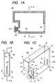
- Figs. 1A to 1C are views which schematically illustrate an ink tank in accordance with one embodiment of the present invention.
- Fig. 1A is a cross-sectional view.
- Fig. 1B is a side view.
- Fig. 1C is a perspective view.
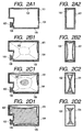
- Figs. 2A1 to 2D2 are views which schematically illustrate changes in the sequence from A to D when the ink, which is contained in the ink tank shown in Figs. 1A to 1C, is led out from the ink supply unit of the ink tank.
- Figs. 2A1, 2B1, 2C1 and 2D1 are cross-sectional views taken along line B-B in Fig. 18.
- Figs. 2A2, 2B2, 2C2 and 2D2 are cross-sectional views taken along line A-A in Fig. 1A.
- the ink tank 100 of the present embodiment shown in Figs. 1A to 1C contains ink in the area (hereinafter referred to as an ink containing portion) surrounded by the inner walls 102 which are separable from the outer walls 101 which form the enclosing walls.
- the outer walls 101 are arranged to structure the container of the ink containing portion to house the ink containing portion. Also, the outer walls 101 are sufficiently thicker than that of the inner walls 102. There is almost no deformation of the outer walls even if the inner walls 102 are deformed when ink flows out. Also, an air inlet 105 is provided for the outer walls.
- the welding portions (pinch offs) 104 are provided for the inner walls. The inner walls are supported by the welding portions so as to engage with the outer walls.
- the thickness of the inner wall area which present the maximum area is thinner on the portions that form the corners than the central area of each face of the substantially polygonal column. This thickness is gradually made smaller from the central portion of each face toward each of the corners, respectively.
- the ink containing side is formed to be convex. In other words, this direction is the same as the one in which deformation is made, hence producing an effect in promoting the deformation of the ink containing portion.
- the corners of the inner walls are formed by three faces. Consequently, the strength of the corners of the inner walls is relatively greater as a whole than that of the central region. Also, in terms of the extended planes thereof, the thickness is smaller than that of the central region, which makes it easer to allow the movement of the planes as described later. It is desirable to make the thickness substantially equal for each of the portions that form the corners of the inner walls.
- the ink supply unit 103 is connected with the ink lead-out tube of ink jet recording means (not shown) through the ink lead-out admission member 106 which is provided with the ink leakage preventive function to prevent it from occurring even when slight vibrations or external pressure is exerted on the ink tank (this is called the "initial state" hereinafter).
- the ink supply unit 103 is structured so that the inner walls and the outer walls are not easily separated by the provision of the ink lead-out admission member 106 and the like.
- the ink supply unit is almost cylindrical, and the ⁇ 1 and ⁇ 2, at which the curved face of the cylinder intersects the flat surface as described later, are provided with the characteristic that these intersections are not easily collapsed by the deformation of the inner walls caused by the lead-out of ink following the ink discharges from the usual ink jet recording means.
- the ink supply unit of the ink tank is almost cylindrical.
- it is not necessarily limited to the cylindrical shape. It may be a polygonal column.
- the size of the ink supply unit is sufficiently smaller than that of the ink containing portion to make it possible to maintain equally such characteristic that it cannot be collapsed easily by the deformation of the inner walls that follows the lead-out of ink. Therefore, it is still possible to maintain the initial state in the ink supply unit where the inner walls and the outer walls are not allowed to be deformed even when ink is completely consumed.
- the outer walls 101 of the ink tank and the inner walls 102 of the ink tank are represented in the schematic Figs. 1A to 1C and Figs. 2A1 to 2D2 as if to maintain the positional relations between them with a gap.
- the inner walls and the outer walls may be structured to be in contact or arranged with a slight gap to separate them if only these walls are in a state of being separable. Therefore, whether in either cases or in the initial state, the ink tank is formed so that the corners ⁇ 2 and ⁇ 2 of the inner walls 102 are positioned at least corresponding to the corners ⁇ 1 and ⁇ 1 of the outer walls 101 following the shape of the inner face of the outer walls 101 (Figs. 2A1 and 2A2).
- the corners of an ink tank formed by a substantially polygonal member are meant to include at least three faces or more preferably, the intersecting portion of the three faces or the portion corresponding to the extended face of such intersecting portion.
- the reference mark ⁇ given to the corners indicates the corners formed by the faces having the ink supply unit, and the reference mark ⁇ indicates the other corners.
- the adscript 1 indicates the outer walls.
- the adscript 2 indicates the inner walls.
- the ink supply unit is formed to be substantially cylindrical.
- the reference mark ⁇ indicates the intersecting portion of the curbed face of the cylinder and the essentially flat surface. In this intersecting portion, the outer walls and the inner walls are positioned correspondingly.
- the inner walls 102 begin to be deformed from the central portion of the face having the maximum area in the direction in which the volume of the ink containing portion is reduced.
- the outer walls function to suppress the deformation of the corners of the inner walls.
- the ink containing portion functions in the direction in which negative pressure is stabilized by the active force exerted by the deformation following the ink consumption, together with the active force whereby to restore the shape to the initial state.
- Figs. 2D1 and 2D2 illustrate this state.
- the contacted sections of the ink containing portion have expanded almost the entire regions of the ink containing portion. Then, some of the corners ⁇ 2 of the inner walls are completely apart from the corresponding corners ⁇ 1 of the outer walls. On the other hand, the corners ⁇ 2 of the inner walls are in a position to be separable from the corresponding corners ⁇ 1 of the outer walls even in the last state, thus becoming to function as the deformation regulating portions to the last.
- the negative pressure which is generated in the ink tank, is also caused to change. This is because the ink tank of the present invention generates negative pressure when the inner walls are deformed following the lead-out of ink.
- the negative pressure is generated mainly by the changes in the restoring force of the deformation of the faces having the maximum areas, which tends to return to the original state following the lead-out of ink.
- the functional bonding resin formed by polyolefine is added to the APL of the intermediate layer in a pellet form at the weight ratio of 7 : 3. With this addition of the functional bonding resin to the APL, the outermost layer and innermost layer can be formed integrally with the intermediate layer so as not to allow them to become separable.
- the structure in such a manner that the outermost layer and the intermediate layer is exchanged, that is, the outermost layer is formed by the APL, and at the same time, the intermediate layer is formed by the EVOH, while the functional bonding resin is added to the EVOH instead of adding it to the APL.
- the functional bonding resin is added to the EVOH, its gas barrier capability is lowered. Therefore, as described at the outset, it is preferable to arrange the structure so that the intermediate layer is formed by the APL, and that the functional bonding resin is added to the APL.
- the APL of the intermediate layer is formed by ring type olefine copolymer, the functional bonding resin is formed by polyolefine, and the outer walls is formed by PP. Therefore, the ink tank of the structural example A has an excellent recycling property.
- the inventor hereof have prepared the comparative example with the outer walls formed by HIPS in a thickness of 1,000 ⁇ m, and also, with the inner walls formed by use of PP in a thickness of 250 ⁇ m.
- Table 3 shows the results of the comparisons between each of the structural examples described above, and the comparative example as to the gas-barrier capability, the moisture absorption of the inner walls, and the changes in the characteristic of negative pressure against the temperature changes, respectively.
- o ⁇ denotes that characteristic is sufficiently satisfactory and stable; ⁇ , characteristic is satisfactory and stable for practical use; ⁇ , characteristic is slightly unsatisfactory and stability is slightly inferior; and X, characteristic is not sufficiently satisfactory and state thereof changes with time, respectively.
- the ink tank provided by the present invention adopts the double-wall structure formed by molding resin material. Then, the outer walls are made thicker to provide strength, while soft material is used for the inner walls to make it thinner still. Hence, it is made possible to follow the voluminal changes of ink contained in the ink tank. It is desirable to use a material having ink resistance for the inner walls, and the one having shock proof or the like for the outer walls.
- the blow molding method there are the injection blowing, the direct blowing, and the double wall blowing, among some others.
- the direct blow molding method is adopted in order to obtain the aforesaid functional effect by use of the resin which is not essentially stretched.
- Figs. 4A to 4D are views which illustrate the manufacturing process of an ink tank in accordance with the present invention.
- Fig. 5 is a flowchart which shows the manufacturing process of the ink tank in accordance with the present invention.
- Figs. 6A1 to 6D2 are views which schematically illustrate each of the steps in the manufacturing process of the ink tank in accordance with the present invention.
- the adscript 1 designates the face having the maximum surface area of the ink tank, and then, the adscript 2 designates the section parallel to the edge face of the ink tank in the central portion thereof in this case.
- the gas-liquid exchanging operation different from the structure of the conventional ink tank (which differs from the conventional gas-liquid exchange in terms of timing) may be performed in some cases. Due to the time lag between the ink lead-out from the ink containing portion 53 and the induction of the air into the ink containing portion 53 when the gas-liquid exchange is made, reliability is increased by the buffer effect or delayed timing in maintaining the stable ink supply even if ink is consumed rapidly, the environment is caused to change, or the external force, such as vibrations, is exerted.
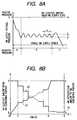
- Fig. 8A is a view which illustrates one example of the changing rate of negative pressure in the ink supply port 12 in this case.
- the axis of abscissa indicates the amount of ink led out from the ink supply port to the outside, and the axis of ordinate indicates negative pressure (static pressure in the ink supply port portion).
- ink is led out in an amount equal to the amount of induced air ultimately after a specific period of time elapses since the induction of the air, for example.
- the gas-liquid exchange of the ink tank embodying the present invention has a time lag as compared with the conventional ink tank whose ink containing portion is not made deformable. Then, as described above, this operation is repeated in the gas-liquid exchanging region. At a certain point, the amount of the air and that of ink are inverted in the ink containing portion 53.
- the inner walls 54 is in a state of being deformed in the inner direction of the tank due to the ink lead-out from the ink containing portion 53 before the gas-liquid exchanges are executed. Then, by the resiliency of the inner walls 54, the externally orientated force is allowed to act always upon the inner walls 54 of the ink containing portion 53. As a result, the amount of air entering the ink containing portion 53, which eases the difference in pressure between the capillary force generating members 13A and 13B, and the ink containing portion 53 at the time of the gas-liquid exchanges, often becomes more than a predetermined amount as described earlier.
- ink tends to be lead out more from the ink containing portion 53 to the container 10 for the capillary force generating members.
- the conventional system structured with the ink containing portion which is not deformable leads out ink immediately to the container for the capillary force generating members as soon as a specific amount of air enters the ink containing portion.
- ink is led out while the ink containing portion 53 is deformed in the inner direction with a further advantage that the buffer effect is made higher still against the external factors, such as vibrations of the carriage, the environmental changes, among some others.
- the liquid supply system of the present embodiment can ease fine changes of negative pressure with the liquid containing portion 53 thus arranged. Further, in accordance with the structure of the present embodiment, it becomes possible to cope with the environmental changes by a solution which is different from the conventional one even when the air is contained in the ink containing portion 53, such as, in the state of the second ink supply.
- the wall faces that form the ink containing portion 53 and the liquid surface are compressed in accordance with the structure of the present embodiment.
- the inner volume of the ink containing portion 53 increases, and at the same time, ink is partly led out from the ink containing portion 53 to the container 10 for the capillary force generating members through the gas-liquid exchanging passage 14.
- the amount of ink led out to the capillary force generating members 13A and 13B is considerably smaller than the case where an ink containing portion 53 is not made deformable.
- the flow resistance in the capillary force generating members 13A and 13B is greater than the resistance against the restoration of the ink containing portion 53. Therefore, along with the air expansion, the inner volume of the ink containing portion 53 is allowed to increase at first. Then, if the voluminal increase due to the air expansion is greater than the upper limit set for the increased volume, ink is led out from the interior of the ink containing portion 53 to the container 10 for the capillary force generating members though the gas-liquid exchanging passage 14. In this manner, the wall faces of the ink containing portion 53 function as buffers against the environmental changes. Thus, the movement of ink in the capillary force generating members 13A and 13B is eased to make the characteristic of negative pressure stabilized in the ink supply port portion.
- the ink which has been led out to the container 10 for the capillary force generating members is retained by the capillary force generating members 13A and 13B.
- the gas-liquid interface is raised due to the provisionally increased amount of ink in the container 10 for the capillary force generating members. Therefore, as in the initial state of use, the inner pressure is temporarily on the positive side slightly more than the stable period of the ink inner pressure.
- the influence that may be exerted on the discharge characteristics of liquid jet recording means of a recording head or the like is small, and there is no problem at all in practice.
- the ink which leaks to the container 10 for the capillary force generating members and retained by the capillary force generating members 13A and 13B, is allowed to return to the ink containing portion 53 again, and at the same time, the value of the ink containing portion 53 is restored to the original one.
- the ink containing portion 53 is deformed as the air expands.
- the inner volume of the ink containing portion 53 increases after expansion from the inner volume of the ink containing portion 53 before expansion.
- the ink retaining level in the container 10 for the capillary force generating members is allowed to change so as to keep balance with the changes of negative pressure due the deformation of the ink containing portion 53.
- negative pressure is in balance with the capillary force generating members 13A and 13B whose negative pressure has been reduced as compared with the one existing before the atmospheric pressure changes due to the ink which has been led out from the ink retaining portion 53.
- the amount of ink to be led out becomes smaller.
- the estimated amount of ink, which is led out from the ink containing portion 53 under the worst condition is made smaller than the case where an ink containing portion 53 is not deformed at all against the air expansion as readily understandable from the representation by the dotted line (1) and the solid line (2).
- the aforesaid phenomenon is the same when the temperature of an ink tank changes.
- the lead-out amount is smaller than the case where the pressure is reduced as described above even if the temperature rises approximately by 50°C.
- the air expansion in the liquid container 50 due to the environmental changes is made allowable even in the liquid container 50 not only by the provision of the container 10 for the capillary force generating members, but also, by the buffer effect produced by increasing the volume of the liquid container 50 itself until the outer contour of the ink containing portion 53 becomes substantially equal to the shape of the inner faces of the housing at the maximum. Therefore, even if the amount of ink to be contained in the liquid container 50 is considerably increased, it is still possible to provide a liquid supply system which can cope with the environmental changes efficiently.
- the axis of abscissa indicates time (t)
- the axis of ordinate indicates the amount of ink led out from the ink containing portion, and the volumes of the ink containing portion.
- the solid line (1) indicates the temporal changes of the amount of ink led out from the ink containing portion
- the solid line (2) indicates the temporal changes of the volumes of the ink containing portion.
- the liquid container 50 can mainly cope with the air expansion before the normal condition of negative pressure balance is kept lastly by means of the container 10 for the capillary force generating members, and the liquid container 50. Therefore, it becomes possible to retard the leading out timing of ink from the liquid container 50 to the container 10 for the capillary force generating members when the environment changes abruptly.
- liquid supply system capable of supplying ink under a stable condition of negative pressure, while the allowance is being enhanced under various use environments against the expansion of the air outside which is induced by the gas-liquid exchanges when the liquid container 50 is in use.
- the voluminal ratio of the container 10 for the capillary force generating members and the ink containing portion 53 can be determined arbitrarily. Then, even when the voluminal ratios between them is larger than 1 : 2, it is practicably possible to use them. Particularly, if the buffer effect of the ink containing portion 53 should be given more importance, it is good enough if only the degree of the deformation should be made greater for the ink containing portion 53 in the gas-liquid exchanging condition in the initial state of use within a range where the elastic deformation is possible.
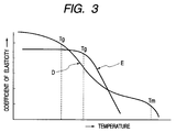
- the structure is formed mainly by the olefine material whose glass transition temperature is low in particular, it is possible to enhance the recycling capability of the product, while maintaining the function of a resistive layer against the environmental temperature changes, if an amorphous polyolefine is used.
Landscapes
- Engineering & Computer Science (AREA)
- Manufacturing & Machinery (AREA)
- Ink Jet (AREA)
- Packages (AREA)
- Containers And Packaging Bodies Having A Special Means To Remove Contents (AREA)
- Containers Having Bodies Formed In One Piece (AREA)
- Thermally Insulated Containers For Foods (AREA)
- Filling Of Jars Or Cans And Processes For Cleaning And Sealing Jars (AREA)
Abstract
Description
| Material |
| 5°C | 35°C | Changes in negative pressure characteristic | |
| PET | -95 mmAq. | -96 mmAq. | OK |
| APL | 115 mmAq. | -110 mmAq. | OK |
| HDPE (Comparative Example) | -140 mmAq. | -30 mmAq. | NG |
| Material | 5°C | 35°C | Changes in elastic modulus | Changes in negative pressure characteristic |
| APL | 22000 kgf/cm2 | 20000 kgf/ | 10% | OK |
| HDPE | 16000 kgf/cm2 | 8000 kgf/ | 50% | NG |
| Structual Example | Gas-barrier capability | Moisture absorption of inner walls | Changes in characteristic of negative pressure against temperature changes |
| A | o ○ | ▵ | o ○ |
| B | o ○ | ▵ | ○ |
| C | o ○ | o ○ | ○ |
| D | ○ | o ○ | ○ |
| Comparative Example | X | o ○ | X |
Claims (14)
- A liquid container comprises an inner wall for forming a liquid containing portion to contain liquid therein; an outer wall for forming a container to contain said liquid containing portion therein; and a liquid supply portion for supplying liquid from said liquid containing portion to the outside, whereinsaid inner wall is a member to generate negative pressure in said liquid containing portion by being deformed following the leading out of liquid, and formed by a material having an elastic modulus change of 25% or less against a temperature change of use environment.
- A liquid container comprises an inner wall for forming a liquid containing portion to contain liquid therein; an outer wall for forming a container to contain said liquid containing portion therein; and a liquid supply portion for supplying liquid from said liquid containing portion to the outside, whereinsaid inner wall is a member to generate negative pressure in said liquid containing portion by being deformed following the leading-out of liquid, and formed by an amorphous resin material having a higher glass transition temperature than a maximum temperature of use environment.
- A liquid container comprises an inner wall for forming a liquid containing portion to contain liquid therein; an outer wall for forming a container to contain said liquid containing portion therein; and a liquid supply portion for supplying liquid from said liquid containing portion to the outside, whereinsaid inner wall is a member to form a multiply layered structure comprising an oxygenproof permeable layer, a resistive layer against an environmental temperature change, and a liquid resistance layer, and said liquid resistance layer is provided for an innermost layer to be in contact with liquid, and said resistive layer against the environmental temperature change is formed by an amorphous resin having a higher glass transition temperature than a maximum temperature of use environment, and then, said inner wall is formed to generate negative pressure in said liquid containing portion by being deformed following the leading-out of liquid.
- A liquid container according to Claim 3, wherein said resistive layer against an environmental temperature change of said inner wall is provided between said liquid resistance layer and said oxygenproof permeable layer, containing a functional bonding resin material.
- A liquid container according to Claim 3, wherein said oxygenproof permeable layer of said inner wall is provided between said liquid resistance layer and said resistive layer against the environmental temperature change, containing a functional bonding resin material.
- A liquid container according to either one of Claim 3 to Claim 5, whereinsaid resistive layer against the environmental temperature change of the inner wall is formed to provide an elastic modulus of 15% change or less following the temperature change of use environment.
- A liquid container according to either one of Claim 1 to Claim 6, wherein said liquid container is installed on a container for a negative pressure generating member capable of generating a gas-liquid exchange for leading out liquid by inducing gas into said liquid containing portion through said liquid supply portion.
- A liquid container according to Claim 3, wherein all the layers for forming said outer wall and the inner wall separable from said outer wall are formed by a material containing ethylene or propylene as the skeletal structure thereof.
- A liquid container according to Claim 3, wherein a resistive layer against the environmental temperature change of said inner wall is formed chiefly by an amorphous polyolefine material.
- A liquid supply system comprising:a liquid container according to either one of Claim 1 to Claim 9; anda container for the negative pressure generating member capable of generating gas-liquid exchange for leading out liquid by inducing gas into said liquid containing portion through said liquid supply portion of said liquid container.
- A liquid supply system according to Claim 10, wherein said liquid container is structured to be attachable to and detachable from said container for the negative pressure generating member.
- A method for manufacturing a liquid container provided with an inner wall for forming a liquid containing portion to contain liquid therein, an outer wall for forming a container to contain said liquid containing portion therein, and a liquid supply portion for supplying liquid from said liquid containing portion to the outside comprising the following steps of:preparing a mold corresponding to an outer contour of said liquid container, a substantially cylindrical first parison having a diameter smaller than that of said mold for use of the outer wall, and a second parison for use of the inner wall; andforming said outer wall and inner wall of said liquid container by injecting the air inside to expand said first and second parisons to follow said mold so as to make an area formed by said inner wall and said area formed by said outer wall separable and substantially analogous, whereinsaid step of preparing said second parison for use of said inner wall comprises a step of preparing a multiply layered parison having an oxygenproof permeable layer, a resistive layer against an environmental temperature change, and a liquid resistance layer.
- A method for manufacturing a liquid container according to Claim 12, said step of preparing said second parison for use of the inner wall further comprising the steps of:preparing said second parison to enable said resistive layer against the environmental temperature change to be placed between said liquid resistance layer and said oxygenproof permeable layer; andcontaining a functional bonding resin material in the resin for forming said resistive layer against the environmental temperature change.
- A method for manufacturing a liquid container according to Claim 12, said step of preparing said second parison further comprising the following steps of:forming said second parison to enable said oxygenproof permeable layer to be placed between said liquid resistance layer and said resistive layer against the environmental temperature change; andcontaining a functional bonding resin material in the resin for forming said oxygenproof permeable layer.
Applications Claiming Priority (2)
| Application Number | Priority Date | Filing Date | Title |
|---|---|---|---|
| JP12061699 | 1999-04-27 | ||
| JP11120616A JP2000309105A (en) | 1999-04-27 | 1999-04-27 | Liquid storage container, liquid supply system, and method of manufacturing the liquid storage container |
Publications (2)
| Publication Number | Publication Date |
|---|---|
| EP1053873A1 true EP1053873A1 (en) | 2000-11-22 |
| EP1053873B1 EP1053873B1 (en) | 2004-09-29 |
Family
ID=14790662
Family Applications (1)
| Application Number | Title | Priority Date | Filing Date |
|---|---|---|---|
| EP00108845A Expired - Lifetime EP1053873B1 (en) | 1999-04-27 | 2000-04-26 | Liquid container, liquid supply system, and method for manufacturing such liquid container |
Country Status (11)
| Country | Link |
|---|---|
| US (1) | US6347865B1 (en) |
| EP (1) | EP1053873B1 (en) |
| JP (1) | JP2000309105A (en) |
| KR (1) | KR100337848B1 (en) |
| CN (1) | CN1149151C (en) |
| AT (1) | ATE277767T1 (en) |
| AU (1) | AU3013700A (en) |
| CA (1) | CA2306612A1 (en) |
| DE (1) | DE60014232T2 (en) |
| MX (1) | MXPA00004068A (en) |
| TW (1) | TW506909B (en) |
Families Citing this family (26)
| Publication number | Priority date | Publication date | Assignee | Title |
|---|---|---|---|---|
| US6450631B1 (en) * | 1999-06-24 | 2002-09-17 | Canon Kabushiki Kaisha | Storing method of ink tank and ink jet head cartridge, and ink tank and storing container used in the same method |
| JP2003155063A (en) * | 2001-08-03 | 2003-05-27 | Canon Inc | Liquid storage container and method of manufacturing the liquid storage container |
| JP4250433B2 (en) | 2002-03-18 | 2009-04-08 | キヤノン株式会社 | Packaging structure of liquid container and method for opening the same |
| US6742861B2 (en) | 2002-07-30 | 2004-06-01 | Hewlett-Packard Development Company, L.P. | Ink delivery system for a miniature inkjet pen |
| USD518516S1 (en) * | 2002-09-10 | 2006-04-04 | Ricoh Company, Ltd. | Printer ink cartridge |
| USD494617S1 (en) | 2002-09-10 | 2004-08-17 | Ricoh Company, Ltd. | Printer ink cartridge |
| USD494616S1 (en) | 2002-09-10 | 2004-08-17 | Ricoh Company, Ltd. | Printer ink cartridge |
| USD497635S1 (en) | 2002-09-10 | 2004-10-26 | Ricoh Company, Ltd. | Printer ink cartridge |
| US6948805B2 (en) * | 2003-04-29 | 2005-09-27 | Hewlett-Packard Development Company, L.P. | Ink cartridge reservoir |
| USD541335S1 (en) | 2003-11-13 | 2007-04-24 | Ricoh Company, Ltd. | Printer ink cartridge |
| US20090020870A1 (en) * | 2005-04-05 | 2009-01-22 | Shinji Watanabe | Electronic device provided with wiring board, method for manufacturing such electronic device and wiring board for such electronic device |
| USD556258S1 (en) * | 2005-12-13 | 2007-11-27 | Ricoh Company, Ltd. | Cartridge for inkjet printer |
| USD549280S1 (en) * | 2005-12-13 | 2007-08-21 | Ricoh Company, Ltd. | Cartridge for inkjet printer |
| JP5955205B2 (en) * | 2012-01-23 | 2016-07-20 | キヤノン株式会社 | Chemical sealing film |
| US20130342618A1 (en) * | 2012-06-22 | 2013-12-26 | Tim Frasure | Fluid container having two sealing films for micro-fluid applications |
| JP6195054B2 (en) * | 2013-03-25 | 2017-09-13 | セイコーエプソン株式会社 | Liquid container |
| JP2016141125A (en) * | 2015-02-05 | 2016-08-08 | セイコーエプソン株式会社 | Liquid storing body |
| JP6308989B2 (en) | 2015-09-30 | 2018-04-11 | キヤノン株式会社 | Liquid storage container and liquid discharge device |
| CN106671607B (en) * | 2015-11-11 | 2018-07-06 | 珠海纳思达企业管理有限公司 | Print cartridge and ink-jet printer |
| JP6723729B2 (en) | 2015-11-17 | 2020-07-15 | キヤノン株式会社 | Liquid storage container and method of manufacturing liquid storage container |
| JP6624905B2 (en) | 2015-11-26 | 2019-12-25 | キヤノン株式会社 | Liquid container and liquid level detector |
| US10391776B2 (en) | 2015-11-30 | 2019-08-27 | Canon Kabushiki Kaisha | Liquid storage container and printing apparatus |
| CN108956438B (en) * | 2018-07-23 | 2020-12-15 | 长安大学 | Ultraviolet radiation-oxygen-temperature-humidity coupled asphalt aging test device and method |
| JP7532055B2 (en) | 2020-03-24 | 2024-08-13 | キヤノン株式会社 | Liquid Supply Unit |
| JP7504641B2 (en) | 2020-03-27 | 2024-06-24 | キヤノン株式会社 | Liquid ejection device |
| JP7520574B2 (en) | 2020-05-22 | 2024-07-23 | キヤノン株式会社 | LIQUID CARTRIDGE AND LIQUID EJECTION DEVICE |
Citations (6)
| Publication number | Priority date | Publication date | Assignee | Title |
|---|---|---|---|---|
| EP0439078A1 (en) * | 1990-01-20 | 1991-07-31 | Gebr. Schmidt Fabrik Fur Feinmechanik | Writing or dosing implement |
| JPH05162244A (en) * | 1991-12-12 | 1993-06-29 | Toyobo Co Ltd | Laminating film for metal plate, laminated metal plate and metal container |
| EP0581531A1 (en) * | 1992-07-24 | 1994-02-02 | Canon Kabushiki Kaisha | Ink container, ink and ink jet recording apparatus using ink container |
| JPH07156934A (en) * | 1993-12-02 | 1995-06-20 | Mitsubishi Plastics Ind Ltd | Polyethylene terephthalate bottle |
| EP0678390A2 (en) * | 1994-04-18 | 1995-10-25 | Hewlett-Packard Company | Collapsible ink cartridge |
| EP0738605A2 (en) * | 1995-04-17 | 1996-10-23 | Canon Kabushiki Kaisha | Liquid accommodating container providing negative pressure, manufacturing method for the same, ink jet cartridge having the container and ink jet recording head as a unit, and ink jet recording apparatus |
Family Cites Families (3)
| Publication number | Priority date | Publication date | Assignee | Title |
|---|---|---|---|---|
| JPH0768776A (en) * | 1993-09-03 | 1995-03-14 | Canon Inc | INK CARTRIDGE, INKJET RECORDING HEAD, AND INKJET RECORDING DEVICE |
| JP3450643B2 (en) * | 1996-04-25 | 2003-09-29 | キヤノン株式会社 | Liquid replenishing method for liquid container, liquid ejection recording apparatus using the replenishing method, liquid replenishing container, liquid container, and head cartridge |
| US6012807A (en) * | 1998-03-06 | 2000-01-11 | Hewlett-Packard Company | Ink containment unit for use in an ink delivery system |
-
1999
- 1999-04-27 JP JP11120616A patent/JP2000309105A/en active Pending
-
2000
- 2000-04-26 AT AT00108845T patent/ATE277767T1/en not_active IP Right Cessation
- 2000-04-26 TW TW089107907A patent/TW506909B/en not_active IP Right Cessation
- 2000-04-26 US US09/558,658 patent/US6347865B1/en not_active Expired - Lifetime
- 2000-04-26 EP EP00108845A patent/EP1053873B1/en not_active Expired - Lifetime
- 2000-04-26 DE DE60014232T patent/DE60014232T2/en not_active Expired - Lifetime
- 2000-04-26 CA CA002306612A patent/CA2306612A1/en not_active Abandoned
- 2000-04-27 AU AU30137/00A patent/AU3013700A/en not_active Abandoned
- 2000-04-27 MX MXPA00004068A patent/MXPA00004068A/en unknown
- 2000-04-27 KR KR1020000022417A patent/KR100337848B1/en not_active Expired - Fee Related
- 2000-04-27 CN CNB001181548A patent/CN1149151C/en not_active Expired - Fee Related
Patent Citations (6)
| Publication number | Priority date | Publication date | Assignee | Title |
|---|---|---|---|---|
| EP0439078A1 (en) * | 1990-01-20 | 1991-07-31 | Gebr. Schmidt Fabrik Fur Feinmechanik | Writing or dosing implement |
| JPH05162244A (en) * | 1991-12-12 | 1993-06-29 | Toyobo Co Ltd | Laminating film for metal plate, laminated metal plate and metal container |
| EP0581531A1 (en) * | 1992-07-24 | 1994-02-02 | Canon Kabushiki Kaisha | Ink container, ink and ink jet recording apparatus using ink container |
| JPH07156934A (en) * | 1993-12-02 | 1995-06-20 | Mitsubishi Plastics Ind Ltd | Polyethylene terephthalate bottle |
| EP0678390A2 (en) * | 1994-04-18 | 1995-10-25 | Hewlett-Packard Company | Collapsible ink cartridge |
| EP0738605A2 (en) * | 1995-04-17 | 1996-10-23 | Canon Kabushiki Kaisha | Liquid accommodating container providing negative pressure, manufacturing method for the same, ink jet cartridge having the container and ink jet recording head as a unit, and ink jet recording apparatus |
Non-Patent Citations (2)
| Title |
|---|
| PATENT ABSTRACTS OF JAPAN vol. 017, no. 565 (M - 1495) 13 October 1993 (1993-10-13) * |
| PATENT ABSTRACTS OF JAPAN vol. 1995, no. 09 31 October 1995 (1995-10-31) * |
Also Published As
| Publication number | Publication date |
|---|---|
| AU3013700A (en) | 2000-11-09 |
| KR20000071833A (en) | 2000-11-25 |
| CA2306612A1 (en) | 2000-10-27 |
| KR100337848B1 (en) | 2002-05-24 |
| CN1273176A (en) | 2000-11-15 |
| US6347865B1 (en) | 2002-02-19 |
| DE60014232D1 (en) | 2004-11-04 |
| TW506909B (en) | 2002-10-21 |
| ATE277767T1 (en) | 2004-10-15 |
| MXPA00004068A (en) | 2005-07-25 |
| CN1149151C (en) | 2004-05-12 |
| JP2000309105A (en) | 2000-11-07 |
| EP1053873B1 (en) | 2004-09-29 |
| DE60014232T2 (en) | 2005-10-13 |
Similar Documents
| Publication | Publication Date | Title |
|---|---|---|
| EP1053873B1 (en) | Liquid container, liquid supply system, and method for manufacturing such liquid container | |
| EP0738605B1 (en) | Liquid accommodating container providing negative pressure, manufacturing method for the same, ink jet cartridge having the container and ink jet recording head as a unit, and ink jet recording apparatus | |
| JPH09286117A (en) | Liquid storage container, method of manufacturing the container, inkjet cartridge and inkjet recording apparatus using the container | |
| JP3245092B2 (en) | Liquid injection method | |
| JP3245088B2 (en) | Liquid ejection head cartridge and liquid container used for the cartridge | |
| US6435673B1 (en) | Liquid container, method of manufacture therefor, ink jet cartridge that uses such container, and ink jet recording apparatus | |
| JP3342372B2 (en) | Large-capacity ink refill containers used in inkjet printing systems | |
| US6655542B2 (en) | Ink tank | |
| US6305794B1 (en) | Liquid container, ink jet cartridge having same and manufacturing method of the container | |
| JP2001001541A (en) | Liquid supply method, liquid supply system, liquid container, ink tank, head cartridge, and ink jet recording apparatus | |
| JPH1044452A (en) | Liquid container for applying negative pressure, method for manufacturing the container, ink jet cartridge integrating the container and ink jet recording head | |
| JP3245090B2 (en) | Liquid container for applying negative pressure, ink jet cartridge integrating the container and ink jet recording head, and method of manufacturing the container | |
| JP3387743B2 (en) | Ink tank | |
| JP3311342B2 (en) | Method of manufacturing liquid storage container giving negative pressure | |
| AU715849B2 (en) | Liquid container | |
| AU731621B2 (en) | Ink container | |
| HK1011955B (en) | Liquid accommodating container providing negative pressure, manufacturing method for the same, ink jet cartridge having the container and ink jet recording head as a unit, and ink jet recording apparatus | |
| JPH1044459A (en) | Liquid storage container | |
| AU741550B2 (en) | Ink container | |
| JPH06155735A (en) | Inkjet head | |
| JPH1044385A (en) | Liquid container for applying negative pressure, ink-jet cartridge and ink-jet recording apparatus integrating this container and ink-jet recording head |
Legal Events
| Date | Code | Title | Description |
|---|---|---|---|
| PUAI | Public reference made under article 153(3) epc to a published international application that has entered the european phase |
Free format text: ORIGINAL CODE: 0009012 |
|
| AK | Designated contracting states |
Kind code of ref document: A1 Designated state(s): AT BE CH CY DE DK ES FI FR GB GR IE IT LI LU MC NL PT SE |
|
| AX | Request for extension of the european patent |
Free format text: AL;LT;LV;MK;RO;SI |
|
| 17P | Request for examination filed |
Effective date: 20010405 |
|
| AKX | Designation fees paid |
Free format text: AT BE CH CY DE DK ES FI FR GB GR IE IT LI LU MC NL PT SE |
|
| 17Q | First examination report despatched |
Effective date: 20020423 |
|
| GRAP | Despatch of communication of intention to grant a patent |
Free format text: ORIGINAL CODE: EPIDOSNIGR1 |
|
| GRAS | Grant fee paid |
Free format text: ORIGINAL CODE: EPIDOSNIGR3 |
|
| GRAA | (expected) grant |
Free format text: ORIGINAL CODE: 0009210 |
|
| AK | Designated contracting states |
Kind code of ref document: B1 Designated state(s): AT BE CH CY DE DK ES FI FR GB GR IE IT LI LU MC NL PT SE |
|
| PG25 | Lapsed in a contracting state [announced via postgrant information from national office to epo] |
Ref country code: IT Free format text: LAPSE BECAUSE OF FAILURE TO SUBMIT A TRANSLATION OF THE DESCRIPTION OR TO PAY THE FEE WITHIN THE PRE;WARNING: LAPSES OF ITALIAN PATENTS WITH EFFECTIVE DATE BEFORE 2007 MAY HAVE OCCURRED AT ANY TIME BEFORE 2007. THE CORRECT EFFECTIVE DATE MAY BE DIFFERENT FROM THE ONE RECORDED.SCRIBED TIME-LIMIT Effective date: 20040929 Ref country code: BE Free format text: LAPSE BECAUSE OF FAILURE TO SUBMIT A TRANSLATION OF THE DESCRIPTION OR TO PAY THE FEE WITHIN THE PRESCRIBED TIME-LIMIT Effective date: 20040929 Ref country code: FR Free format text: LAPSE BECAUSE OF FAILURE TO SUBMIT A TRANSLATION OF THE DESCRIPTION OR TO PAY THE FEE WITHIN THE PRESCRIBED TIME-LIMIT Effective date: 20040929 Ref country code: NL Free format text: LAPSE BECAUSE OF FAILURE TO SUBMIT A TRANSLATION OF THE DESCRIPTION OR TO PAY THE FEE WITHIN THE PRESCRIBED TIME-LIMIT Effective date: 20040929 Ref country code: AT Free format text: LAPSE BECAUSE OF FAILURE TO SUBMIT A TRANSLATION OF THE DESCRIPTION OR TO PAY THE FEE WITHIN THE PRESCRIBED TIME-LIMIT Effective date: 20040929 Ref country code: FI Free format text: LAPSE BECAUSE OF FAILURE TO SUBMIT A TRANSLATION OF THE DESCRIPTION OR TO PAY THE FEE WITHIN THE PRESCRIBED TIME-LIMIT Effective date: 20040929 |
|
| REG | Reference to a national code |
Ref country code: GB Ref legal event code: FG4D |
|
| REG | Reference to a national code |
Ref country code: CH Ref legal event code: NV Representative=s name: BOVARD AG PATENTANWAELTE Ref country code: CH Ref legal event code: EP |
|
| REG | Reference to a national code |
Ref country code: IE Ref legal event code: FG4D |
|
| REF | Corresponds to: |
Ref document number: 60014232 Country of ref document: DE Date of ref document: 20041104 Kind code of ref document: P |
|
| PG25 | Lapsed in a contracting state [announced via postgrant information from national office to epo] |
Ref country code: SE Free format text: LAPSE BECAUSE OF FAILURE TO SUBMIT A TRANSLATION OF THE DESCRIPTION OR TO PAY THE FEE WITHIN THE PRESCRIBED TIME-LIMIT Effective date: 20041229 Ref country code: DK Free format text: LAPSE BECAUSE OF FAILURE TO SUBMIT A TRANSLATION OF THE DESCRIPTION OR TO PAY THE FEE WITHIN THE PRESCRIBED TIME-LIMIT Effective date: 20041229 Ref country code: GR Free format text: LAPSE BECAUSE OF FAILURE TO SUBMIT A TRANSLATION OF THE DESCRIPTION OR TO PAY THE FEE WITHIN THE PRESCRIBED TIME-LIMIT Effective date: 20041229 |
|
| PG25 | Lapsed in a contracting state [announced via postgrant information from national office to epo] |
Ref country code: ES Free format text: LAPSE BECAUSE OF FAILURE TO SUBMIT A TRANSLATION OF THE DESCRIPTION OR TO PAY THE FEE WITHIN THE PRESCRIBED TIME-LIMIT Effective date: 20050109 |
|
| NLV1 | Nl: lapsed or annulled due to failure to fulfill the requirements of art. 29p and 29m of the patents act | ||
| PG25 | Lapsed in a contracting state [announced via postgrant information from national office to epo] |
Ref country code: LU Free format text: LAPSE BECAUSE OF NON-PAYMENT OF DUE FEES Effective date: 20050426 Ref country code: IE Free format text: LAPSE BECAUSE OF NON-PAYMENT OF DUE FEES Effective date: 20050426 Ref country code: CY Free format text: LAPSE BECAUSE OF FAILURE TO SUBMIT A TRANSLATION OF THE DESCRIPTION OR TO PAY THE FEE WITHIN THE PRESCRIBED TIME-LIMIT Effective date: 20050426 |
|
| PG25 | Lapsed in a contracting state [announced via postgrant information from national office to epo] |
Ref country code: MC Free format text: LAPSE BECAUSE OF NON-PAYMENT OF DUE FEES Effective date: 20050430 |
|
| PLBE | No opposition filed within time limit |
Free format text: ORIGINAL CODE: 0009261 |
|
| STAA | Information on the status of an ep patent application or granted ep patent |
Free format text: STATUS: NO OPPOSITION FILED WITHIN TIME LIMIT |
|
| 26N | No opposition filed |
Effective date: 20050630 |
|
| EN | Fr: translation not filed | ||
| PG25 | Lapsed in a contracting state [announced via postgrant information from national office to epo] |
Ref country code: PT Free format text: LAPSE BECAUSE OF NON-PAYMENT OF DUE FEES Effective date: 20050228 |
|
| REG | Reference to a national code |
Ref country code: CH Ref legal event code: PFA Owner name: CANON KABUSHIKI KAISHA Free format text: CANON KABUSHIKI KAISHA#30-2, 3-CHOME, SHIMOMARUKO, OHTA-KU#TOKYO (JP) -TRANSFER TO- CANON KABUSHIKI KAISHA#30-2, 3-CHOME, SHIMOMARUKO, OHTA-KU#TOKYO (JP) |
|
| PGFP | Annual fee paid to national office [announced via postgrant information from national office to epo] |
Ref country code: CH Payment date: 20130417 Year of fee payment: 14 |
|
| REG | Reference to a national code |
Ref country code: CH Ref legal event code: PL |
|
| PG25 | Lapsed in a contracting state [announced via postgrant information from national office to epo] |
Ref country code: CH Free format text: LAPSE BECAUSE OF NON-PAYMENT OF DUE FEES Effective date: 20140430 Ref country code: LI Free format text: LAPSE BECAUSE OF NON-PAYMENT OF DUE FEES Effective date: 20140430 |
|
| PGFP | Annual fee paid to national office [announced via postgrant information from national office to epo] |
Ref country code: GB Payment date: 20150424 Year of fee payment: 16 Ref country code: DE Payment date: 20150430 Year of fee payment: 16 |
|
| REG | Reference to a national code |
Ref country code: DE Ref legal event code: R119 Ref document number: 60014232 Country of ref document: DE |
|
| GBPC | Gb: european patent ceased through non-payment of renewal fee |
Effective date: 20160426 |
|
| PG25 | Lapsed in a contracting state [announced via postgrant information from national office to epo] |
Ref country code: DE Free format text: LAPSE BECAUSE OF NON-PAYMENT OF DUE FEES Effective date: 20161101 Ref country code: GB Free format text: LAPSE BECAUSE OF NON-PAYMENT OF DUE FEES Effective date: 20160426 |