EP1053534B1 - Post-processing decompressed images - Google Patents
Post-processing decompressed images Download PDFInfo
- Publication number
- EP1053534B1 EP1053534B1 EP99960989A EP99960989A EP1053534B1 EP 1053534 B1 EP1053534 B1 EP 1053534B1 EP 99960989 A EP99960989 A EP 99960989A EP 99960989 A EP99960989 A EP 99960989A EP 1053534 B1 EP1053534 B1 EP 1053534B1
- Authority
- EP
- European Patent Office
- Prior art keywords
- block
- pixel
- quantities
- blocks
- post
- Prior art date
- Legal status (The legal status is an assumption and is not a legal conclusion. Google has not performed a legal analysis and makes no representation as to the accuracy of the status listed.)
- Expired - Lifetime
Links
Images


Classifications
-
- G—PHYSICS
- G06—COMPUTING OR CALCULATING; COUNTING
- G06T—IMAGE DATA PROCESSING OR GENERATION, IN GENERAL
- G06T9/00—Image coding
Definitions
- the present invention relates to systems and methods for post-processing decompressed images in order to minimize perceptual artifacts due to prior image compression, and in particular to minimize blocking artifacts.
- Decompressing images so compressed which necessarily involves steps of dequantization and inverse DCT of the received quantized coefficients in order to derive a received decompressed image, can lead to what are called herein "blocking artifacts" in the following manner.
- the quantization errors introduced can become especially apparent and even objectionable.
- errors in the low spatial frequency components can make the individual, independent 8X8 blocks perceptually apparent. This is especially so if low frequency components, which smoothed the block-to-block boundaries in the source image, are set to zero.
- Blocks can be overlapped in the source image in order to redundantly encode block-to-block boundaries, but at the cost of decreased compression and increased required communication bandwidth.
- the objects of the present invention are to provide systems and methods for post-processing decompressed images in order to minimize blocking artifacts and which overcome the above identified problems in the current art.
- the invention provides a method and a system as defined in the independent Claims.
- the dependent Claims define advantageous embodiments.
- the corrections added to the pixel values by the methods of this invention more closely match the actual errors and artifacts introduced by the image blocking process.
- these objects are achieved by determining an 8X8 matrix of correction values for each processed 8X8 pixel block in an image.
- the correction matrices are then added to the pixel blocks in order to derive post-processed pixel blocks with minimized blocking artifacts.
- the resulting pixel values of the corrected pixel blocks blend with pixel values of adjacent blocks, also typically corrected. in a perceptually smooth manner with minimum block-to-block artifacts.
- the correction matrices are derived from differences between values of pixels along the edges of a block to be post-processed and pixels along the edges of the four orthogonally adjacent pixel blocks.
- the correction matrix is derived from zero-frequency ("DC") transform coefficients of a pixel block to be post-processed and the four adjacent pixel blocks.
- the 8X8 matrix of correction values is either derived directly according to a preferred entirely spatial-domain interpolation, or derived indirectly by an alternative computation from a smaller 4X4 spatial-domain intermediary error correction matrix.
- Direct and inverse transforms of the intermediary correction matrix to and back from a frequency domain accomplish smooth interpolation of the smaller intermediary matrix to an 8X8 matrix of correction values.
- decoded blocks are selected for post-processing principally in relatively flat or featureless image regions. Such image regions are most likely to have perceptually apparent blocking artifacts.
- Fig. 1A generally illustrates an embodiment of a system according to the present invention, represented within box 4, in conjunction with a conventional image decoder system, including input 1, decoder 2, and image buffer 3.
- the present invention is adaptable to decoded images that were encoded by any process that divides an original image into non-overlapping, rectangular blocks of pixels, and independently encodes each such rectangular block.
- the invention is described with respect to such conventional families of compression standards as JPEG, MPEG, and H.320, according to which an original image is divided into non-overlapping and independent 8X8 blocks of pixels, which are encoded as quantized DCT coefficients.
- the invention is most effective when the images are highly compressed, and, accordingly, when quantization of the DCT coefficients is aggressive or coarse.
- Exemplary of such compression levels is compression to 0.25 or less bits of luminance information per pixel.
- Encoded images are input at 1 to the conventional decoder system illustrated. Decoder 2 then performs conventional decoding of the input images according to the encoding method, and stores decoded images temporarily in image buffer 3. In the absence of the present invention, the images are directly output from the image buffer. The present invention adds the processing elements and steps represented within box 4 to such a conventional decoder.
- first processing operation 5 determine block differences
- quantities representative of blocking artifacts in a decoded or decompressed image are determined for all blocks from various aspects block-to-block pixel value differences. Preferably, four such representative quantities are determined for each pixel block.
- second processing operation (select blocks to process) 6 the individual blocks to be post-processed by the present invention are selected heuristically in view of the determined block-to-block differences. In one embodiment, if any of these differences exceed a threshold value, the block is not processed: alternatively, if the differences exceed the threshold, their values are set down to that threshold.
- This step reflects the discovery of the inventor that large block-to-block differences are likely caused by structure actually present in the original image, while small block-to-block differences typically reflect blocking artifacts present in relatively featureless regions on the original image. These should be corrected.
- third processing operation determine 8x8 correction matrices 7 7 for each post-processed 8X8 block, an 8X8 matrix of correction values is determined according to the alternative embodiments to be described subsequently. The correction values are determined to smoothly link the post-processed block to its orthogonally-adjacent blocks. Processing of the blocks in the image buffer can be sequential or in parallel according to the available hardware.
- the DC coefficients (i.e ., zero frequency coefficients) transmitted in the encoded images can be used in processing step 5 to determine the block-to-block differences.
- the decoder 2 it is advantageous for the decoder 2 to make these coefficients available to determine block differences unit 5 over connection 9, which can include a coefficient buffer as needed.
- Fig. 1A illustrates one or more processors 11 for decoding images and performing the operations of the present invention, one or more RAM modules 12 for storing image data and/or program instructions, optionally one or more ROM modules 13 for storing program instructions, one or more I/O interface devices 14 for communicating with other systems, and one or more busses 15 for connecting these individual components.
- the processors include one or more digital signal processors ("DSP"), such as the TM-1000 type DSP (Philips Electronics North America Corp.) or the TMS-3000 type DSP (Texas Instruments. Inc.).
- DSP digital signal processors
- the present invention further comprises computer readable media on which are recorded or encoded program instructions for causing processors to perform the processing operation of the system.
- Such media can include magnetic media, such as floppy discs. hard discs, tapes. and so forth, optical media, such as CD-ROMS, and other media technologies usable in the art.
- processing operations 5-7 (Fig. 1A) are next described in detail.
- processing operation 5 (Fig. 3), which according to the present invention are taken to be representative of blocking artifacts, is described with reference to the candidate pixel blocks illustrated in Figs. 2A-B.
- FIGs. 2A-B Although these figures and the subsequent discussion treats the common case of 8X8 pixel blocks, one of average skill will immediately appreciate how to modify the methods to be described in case rectangular pixel blocks of sizes other than 8X8 are used in a particular compression method.
- Fig. 2A For candidate, central pixel block C in Fig. 2A, block-to-block pixel differences are determined with respect to the four, orthogonally-adjacent pixel blocks sharing edges with candidate, central block C. These blocks are labeled W (to the west of C), N (to the north of C), E (to the east of C), and S (to the south of C) in Fig. 2A. Diagonally adjacent pixel blocks are not directly considered.
- Fig. 2B illustrates pixel blocks C, N, E, W, and S in more detail in the case where the relevant image compression methods use 8X8 pixel blocks. Edge pixels for all these blocks are indicated in standard matrix notation.
- DC coefficients zero frequency coefficients
- N DC the DC coefficients for these blocks
- E DC the DC coefficients for these blocks
- W DC the DC coefficients
- a first method for determining block-to-block pixel differences computes the average differences between pixels along each edge of block C and pixels along adjacent edges of blocks N, E, W, and S.
- Four quantities are returned, each reflecting the block-to-block differences along an edge of central block C.
- This preferred method directly and with minimum computation, returns values representative of pixel-value discontinuities at the boundaries of a pixel block.
- the following equations are representative of this method. where the four quantities N, E. W. and S are average edge-adjacent pixel differences along the north, east, west, and south edges of central block C, respectively.
- Factor FA is a multiplicative weighting factor for scaling these edge differences. It is described subsequently in more detail in conjunction with second weighting factor FB.
- a third alternative method captures increased detail of block-to-block pixel differences along block edges by computing sub-edge differences.
- the methods above which determine only four quantities, one for each edge of a central block, necessarily represent, therefore, only average differences along an entire edge.
- perceptual blocking artifacts can also reflect variations in block-to-block pixel differences along each edge, as well as simply block-to-block average differences.
- the third alternative method captures such variations in intensity by computing more than one quantity for each edge, each quantity representing the differences in one or more pairs of edge-adjacent pixels of central block C. instead of merely the average of all pixels along an edge. In a case where averages of the differences of two adjacent pairs of pixels are computed, the following equations are representative of the third alternative.
- A 0.250*FA*((W 17 - C 10 ) + (W 07 - C 00 ) + (N 70 - C 00 ) + (N 71 - C 01 ) ⁇
- D 0.250*FA* ⁇ (N 76 - C 06 ) + (N 77 - C 07 ) + (E 00 - C 07 ) + (E 01 - C 17 ) ⁇
- E 0.500*FA* ⁇ (E 20 - C 27 ) + (E 30 - C 37 ) ⁇
- F 0.500*FA* ⁇ E 40 - C 47 ) + (E 50 - C 57 ) ⁇
- G 0.250*FA* ⁇ (E 60 - C 67 ) + (E 70 - C 77 )
- quantities J, I, H, and G represent differences between pair of pixels in the outlined sub-blocks 16. 17, 18, and 19, respectively.
- a finer representation could be used, for example one in which a quantity is computed from the difference of each pair of edge-adjacent pixels.
- a coarser representation could be used by combining certain of the above quantities. For example, the following combined and coarser quantities can be used.
- blocks are selected for post-processing in view of heuristic block selection criteria that depend on the block-to-block pixel differences determined above.
- the overall goal and purpose of the system and method of the present invention is to achieve perceptually improved images. and not to post-process images merely to achieve certain mathematical effects or consistency without regard to perceptual changes.
- the methods of the present invention include heuristic block selection criteria, adjustable weighting factors for block-to-block pixel differences, and computational alternatives that can be adjusted or selected in particular cases to obtain maximum perceptual improvements, in general or with respect to image classes or interest, within the processing resources available.
- block selection criteria are derived from the discovery of the inventor that in many cases block-to-block pixel differences represent image structures in a source image whose correction can result in perceptually objectionable image alterations. Such differences are likely to represent real image structure where the differences along one or more edges are particularly "large”. In contrast, where block-to-block differences are "small", the actual image is likely to be relatively flat or featureless, i.e ., devoid of particularly apparent structure. In such regions small blocking artifacts are most perceptually apparent, and, therefore, should be corrected according to the present invention. Additionally, "small" block-to-block pixel difference are also a likely indicator of differences due only to blocking artifacts.
- “Small” is advantageously measured in view of a particular image compression algorithm as that degree of block-to-block pixel differences which are of a magnitude likely to be due to quantization errors in the low frequency transform coefficients, in particular as that degree of block-to-block pixel differences resulting from zeroing of low frequency transform coefficients as a result of coarse quantization and subsequent dequantization.
- a "small” difference is taken to be of the magnitude of this quantization error, or in other words preferably approximately 2-4 times such quantization error.
- a "large” block-to-block pixel difference is preferably 5 or more times such quantization error. Therefore, block with "small” block-to-block pixel differences are post-processed. while block with large differences are not.
- "small” is preferably a block-to-block difference of less than 5. and more preferably less than 2.
- a "large difference is preferably 6, or more preferably 8, or more. Exact values are advantageously selected to achieve the maximum perceptual improvement.
- any pixel block having any block-to-block difference with an adjacent block which is greater than the selected threshold is not processed.
- all blocks can be processed but any block-to-block difference exceeding the selected threshold value is set back to and limited by the threshold value. This latter alternative is advantageous in order to correct blocks with one side bordering actual image structure and another side bordering flat or featureless image regions.
- blocks with little AC (non-zero frequency) energy are chosen for processing. For example, blocks with no more than 5%, or more preferably no more than 3%, of their energy in the AC terms are selected for processing.
- processing operation 7 next determines matrices of error correction values which are added to the processed blocks by adder 8 to finally arrive at corrected blocks.
- the error correction matrices are the same size as the pixel blocks. Corrected images result from processing all pixel blocks in the images.
- Fig. 3 illustrates processing operation 7 in more detail as having two principal alternatives, preferred operation 7' and alternative operation 7".
- the block-to-block pixel differences are directly converted into an 8X8 (or other size) error correction matrix.
- the differences are first converted (20) into a 4X4 intermediate error matrix. which is then smoothly expanded into a final 8X8 error correction matrix by a transform (21) to a 4x4 frequency domain matrix, an embedding (22) in an 8x8 matrix, and an inverse transform (23) to an 8x8 spatial matrix.
- preferred operation 7' interpolates the error correction matrix elements from the block-to-block pixel differences determined along each edge. This interpolation is done in a dimension independent manner. in that each matrix element has independent. weighted contributions from each determined block-to-block, pixel difference, and each determined block-to-block pixel difference contributes independently only to matrix elements in that row or column of that particular pixel difference. For example. in case of a value representing the average difference of edge-adjacent pixels along an entire edge. the value is interpolated along all rows or columns perpendicular to that edge.
- the weights of the pixel differences have a chosen a spatial configuration and a selected overall multiplicative weight, FA*FB.
- the spatial configuration is chosen, limited by constraints, in order to result in a maximum perceptual improvement.
- One constraint is that the maximum spatial weight occur adjacent to the block edge of that block-to-block difference to be interpolated.
- Another constraint is that the sum of the weights be zero in order that the average brightness of the pixel block does not change.
- a final heuristic constraint is that a difference at one edge of a pixel block coupled with another difference of the same size but different sign at the opposite edge (along a row or column) should interpolate to a uniform gradient between the two edges.
- Fig. 4C illustrates the spatial configuration weights for creating the 8X8 error correction matrix of the preferred alternative.
- the maximum weight occurs next to the interpolated block-to-block pixel difference.
- the sum of the weights is clearly zero.
- a unit positive pixel difference at a left edge together with a unit negative pixel difference at a right edge is interpolated by the spatial configuration of Fig. 4C into the preferred linear gradient of Fig. 4D.
- One of average skill will understand how to expand or compress this preferred spatial configuration for other pixel array sizes.
- the overall multiplicative factor, FA*FB is also selected. limited by constraints, in order to result in a maximum perceptual improvement.
- the overall factor is divided between a weight factor for the block-to-block pixel difference, FA, and a weight factor for the error correction matrix, FB.
- the overall factor, FA*FB is less then or equal 0.500 so that edges between adjacent corrected pixel blocks are not over corrected, that is so that corrected pixel blocks have their block-to-block edge differences reduced without changing the direction of that edge difference.
- the overall factor is less than 0.500 because, in the presence of pixel-value gradients, a certain block-to-block edge difference can be an actual image feature and should not be eliminated.
- FA is taken as 1.0. so that the block-to-block pixel differences represent unscaled pixel values.
- FB is advantageously taken as 0.375 as this factor gives good perceptual results and is rapid to compute by shifts and additions without multiplications.
- the N, E, W. and S input difference values are preferably determined as the average differences of edge-adjacent pixels described above, or alternative as the difference in the DC coefficients, also described above.
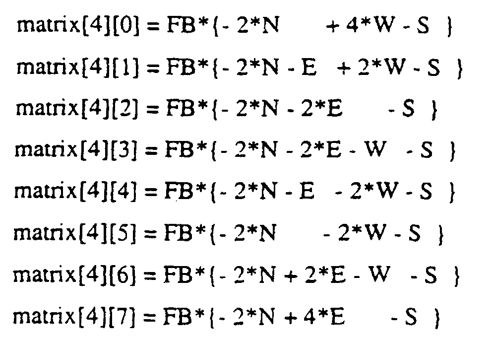
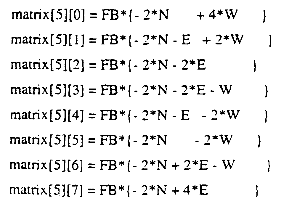
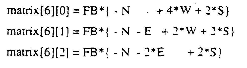
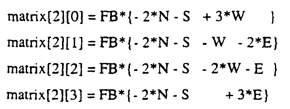
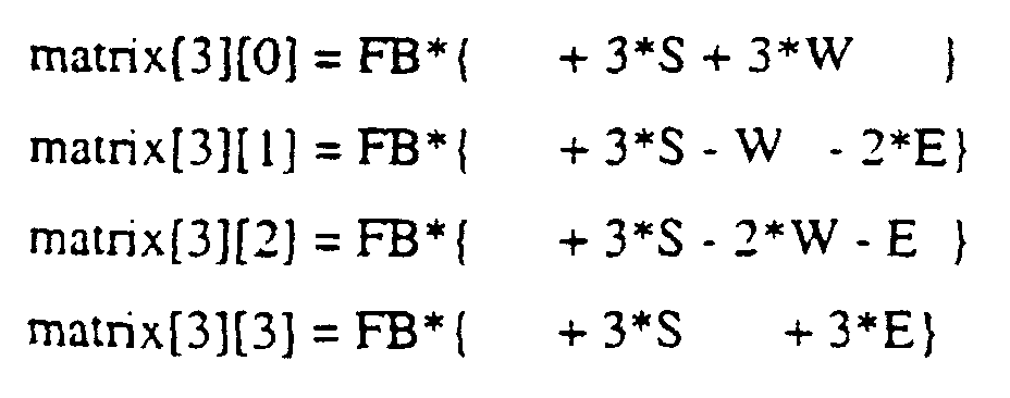
- the following equations defining this matrix are exemplary.
- the output is the 8X8 error correction matrix.
- this embodiment determines an error correction matrix which has a size that is smaller than the size of a pixel block and then expands this smaller error correction matrix to the size of the pixel block.
- the smaller error correction matrix preferably has a size that is a rational fraction of the size of the pixel block, e.g., a 4X4 size when the pixel block size is 8X8.
- the smaller error correction matrix is preferably expanded in a smooth fashion. For example, this expansion can be done by transforming to a transform domain followed by inverse transforming, with higher frequency coefficients set to zero, from that transform domain to a matrix the size of a pixel block.
- processing operation 7" of Fig 3 is illustrated as commencing with operation 20, determination of a 4X4 error matrix.
- this 4X4 matrix is determined similarly to the 8X8 matrix discussed above, that is matrix elements are interpolated from the block-to-block pixel differences determined along each edge in a dimension independent manner, such that each matrix element has independent. weighted contributions from each perpendicularly-related block-to-block- pixel difference. These pixel differences weights also have a chosen spatial configuration and a selected overall multiplicative weight. FA*FB.
- the spatial configuration is preferably chosen according to the principles discussed above. Fig.
- FIG. 4A illustrates a preferred spatial weight configuration having elements that sum to zero and which results in a linear gradient between equal but opposite differences at each edge of the 4X4 matrix. as illustrated in Fig. 4B.
- the N, E. W, and S input block-to-block pixel differences are preferably determined as the average differences of edge-adjacent pixels described above, or alternative as the differences in the DC coefficients, also described above.
- FB 0.375 multiplied by 1.0/3.0, the spatial configuration normalization factor.
- this 4X4 matrix can be determined from pixel sub-edge differences, which reflect finer structure of the block-to-block pixel differences along an edge. Exemplary of such sub-edge differences are the quantities A-L discussed above.
- these sub-edge difference can be placed around the edges of the 4X4 matrix, one sub-edge difference being placed in the 4X4 matrix at a position corresponding to the position of original pixels in the original 8X8 matrix.
- the central four matrix elements can be set to zero. The following equations are representative of this alternative, with FB being preferably 0.375.
- the inner four matrix elements can be interpolated from the edge elements in a dimension independent manner using the spatial configuration weights of Fig. 4A.
- next processing operations of alternative 7" expand the 4X4 matrix into an 8X8 matrix in a smooth manner, that is introducing only a minimum of higher spatial frequency components into the final 8X8 matrix.
- the 4X4 matrix is transformed into a 4X4 matrix in a suitable frequency domain.
- a DCT transform is preferred, but this invention is adaptable to other transforms, such as the computationally inexpensive Hadamard transform.
- the 4X4 frequency domain matrix is embedded in an 8X8 frequency domain matrix with all the remaining elements set to 0.
- certain elements in the 4X4 matrix such as the bottom-most row and right-most column, may also be set to zero. Thereby the higher frequency components represented by these matrix elements are zero.
- the 8X8 frequency domain matrix is inverse transformed into an 8X8 spatial domain error correction matrix, which is used in the subsequent steps of this invention just as the 8X8 matrix of the preferred alternative is used.
- the inverse transform is the same as the forward transform, that is an inverse DCT is used in step 23 if a DCT is used in step 21.
- the 8X8 error correction matrix resulting from either the preferred embodiment or the alternative embodiment is then added to the original pixel block to result in a pixel block corrected for blocking artifacts. This process is repeated for all pixel blocks in the image in order to derive a corrected image.
- the parameters of this method in particular the block selection threshold and the overall weighting factor values, can be optimized to give maximum perceptual improvement.
- equations presented above are exemplary of one embodiment of the methods described.
- One of skill in the art will immediately appreciate how their form could be improved for computational efficiency in micro-processors and digital signal processors of various architectures.
- the total number of arithmetic operations can be reduced by factorization in view of the dimension independence of the 8X8 and 4X4 matrices.
- multiplicative operations including the overall multiplicative weight factor, can be implemented by less costly shifts and additions, instead of more costly multiplications.
- Fig. 5 is a 640X480 test image created by expanding each pixel of a 320X240 monochrome source image to four identical neighboring pixels.
- the source image has a luminance varying between 64 and 192 in a total range of 0 to 255 according to the following equations.
- Fig. 6 is a DCT transform of this image with all DCT coefficients set to zero except for the DC coefficients. It represents a maximally compressed version of Fig. 5 having a maximum of blocking artifacts. Each 8X8 pixel block is clearly apparent.
- Fig. 7 is a version of Fig. 6 post-processed according to the following early embodiment of the present invention.
- Sub-edge pixel differences A-L were determined as discussed above, resulting in four block-to-block pixel differences for each edge of each 8X8 pixel block.
- These coefficients were placed appropriately around the edge of a 4X4 matrix, as described for an alternative embodiment of processing operation 7". and were then Hadamard transformed.
- the overall weighting factor was 0.125, a very conservative value compared to the preferred value of 0.375.
- Fig. 7 is certainly perceptually much improved, the extreme blocking artifacts being much reduced and even eliminated in the central regions of the image.
- the example illustrates the power of the system and method of this invention to achieve substantial reduction in blocking artifacts of image compression algorithms by using only simple and computationally inexpensive processing operations.
- any reference signs placed between parentheses shall not be construed as limiting the Claim.
- the word “comprising” does not exclude the presence of elements or steps other than those listed in a Claim.
- the word “a” or “an” preceding an element does not exclude the presences of a plurality of such elements.
- the invention can be implemented by means of hardware comprising several distinct elements, and by means of a suitably programmed computer. In the device Claim enumerating several means, several of these means can be embodied by one and the same item of hardware.
Landscapes
- Engineering & Computer Science (AREA)
- Multimedia (AREA)
- Physics & Mathematics (AREA)
- General Physics & Mathematics (AREA)
- Theoretical Computer Science (AREA)
- Compression Or Coding Systems Of Tv Signals (AREA)
- Compression Of Band Width Or Redundancy In Fax (AREA)
- Image Processing (AREA)
Description





Claims (16)
- A method for post-processing a decompressed image, the image having been compressed by a process including compression of rectangular blocks of pixels covering the original image, said method comprising:determining blocking artifact quantities for each pixel block (5) in the decompressed image that are representative of blocking artifacts, wherein the blocking artifact quantities for a pixel block are determined from block-to-block differences between that pixel block and pixel blocks adjacent to that pixel block,selecting pixel blocks (6) for post-processing for which the blocking artifact quantities are less than a threshold value,determining (7',7") an error correction matrix for each selected pixel block from the blocking artifact quantities for that selected pixel block, andadding the error correction matrices to the selected pixel blocks to derive post-processed pixel blocks and the post-processed image.
- The method of Claim 1 wherein the blocking artifact quantities for a pixel block are four quantities determined from the four differences between averages of values of pixels along each edge of that pixel block and averages of values of pixels along adjacent edges of the adjacent pixel blocks.
- The method of Claim I wherein the blocking artifact quantities for a pixel block are determined from averages of differences between the values of pixels of each of two or more adjacent pairs of pixels, and wherein for each pair of pixels one pixel of that pair is at an edge of that pixel block and the other pixel of that pair is adjacent at an adjacent edge of the adjacent pixel block.
- The method of Claim 1 wherein the blocking artifact quantities for a pixel block are four quantities determined from the four differences between a zero-frequency transform coefficient of that pixel block and zero-frequency transform coefficients of the four orthogonally adjacent pixel blocks.
- The method of Claim 1 wherein the threshold value used in the selecting step is one to four times the magnitude of errors in pixel values introduced by the combined steps of transforming, quantizing, dequantizing, and inverse transforming applied to pixel blocks.
- The method of Claim 1 wherein said selecting selects pixel blocks for which all of the four or more quantities are less than the threshold value.
- A method for post-processing a decompressed image, the image having been compressed by a process including compression of rectangular blocks of pixels covering the original image, said method comprising:determining blocking artifact quantities for each pixel block (5) in the decompressed image that are representative of blocking artifacts, wherein the blocking artifact quantities for a pixel block are determined from block-to-block differences between that pixel block and pixel blocks adjacent to that pixel block,selecting all pixel blocks (6) for post-processing,setting to threshold value any of the blocking artifact quantities for each pixel block which are greater than the threshold value,determining (7', 7") an error correction matrix for each selected pixel block from the blocking artifact quantities for that selected pixel block, andadding the error correction matrices to the selected pixel blocks to derive post-processed pixel blocks and the post-processed image.
- The method of Claim 1 or 7 wherein each error correction matrix is determined by a process comprising linearly interpolating the blocking artifact quantities (7',20) according to selected spatial configuration weights in order to determine elements of the error correction matrices.
- The method of Claim 8 wherein said linear interpolation is performed in a dimensionally-independent manner in that each matrix element has independent, weighted contributions from each determined block-to-block pixel difference, and each determined block-to-block pixel difference contributes independently only to matrix elements in that row or column of that particular pixel difference.
- The method of Claim 9 wherein the spatial configuration weights are selected such that (i) the largest weight is applied at the edge associated with the quantity to be interpolated, (ii) the sum of the spatial configuration weights is zero, and (iii) the interpolation of equal quantities of opposite sign at two opposite edges result in a linear gradient of error correction matrix elements between the two opposite edges.
- The method of Claim 10 wherein the pixel blocks have a size of 8X8 pixels, and wherein the spatial configuration weights have values +4, +2, 0, -1, -2, -2, -1, and 0, wherein the maximum weight occurs next to the interpolated block-to-block pixel difference.
- The method of Claim 1 or 7 wherein said determining an error correction matrix comprises:determining an intermediary error correction matrix (20) having a size smaller than the size of the pixel blocks by linearly interpolating four or more blocking artifact quantities in a dimensionally independent manner in that each matrix element has independent, weighted contributions from each determined block-to-block pixel difference, and each determined block-to-block pixel difference contributes independently only to matrix elements in that row or column of that particular pixel difference,transforming the intermediary error correction matrix (21) to a transform domain, andinverse transforming the transformed intermediary error correction matrix (23) to the error correction matrix, wherein for said inverse transformation selected higher frequency transform coefficients are set to zero (22).
- The method of Claim I or 7 wherein the error correction matrix is determined so that block-to-block pixel differences between two adjacent post-processed pixel blocks are smaller than but of the same sign as the block-to-block pixel differences between those two adjacent pixel blocks prior to post-processing.
- A system for post-processing a decompressed image, the image having been compressed by a process including compression of rectangular blocks of pixels covering the original image, said system comprising:means for determining blocking artifact quantities (5) for each pixel block in the decompressed image that are representative of blocking artifacts, wherein the blocking artifact quantities for a pixel block are determined from block-to-block differences between that pixel block and pixel blocks adjacent to that pixel block,means for selecting pixel blocks for post-processing (6) according to the blocking artifact quantities for each pixel block and a threshold value,means for determining an error correction matrix (7) for each selected pixel block from the blocking artifact quantities for that selected pixel block, andmeans for adding (8) the error correction matrices to the selected pixel blocks to derive post-processed pixel blocks and the post-processed image.
- A system for post-processing a decompressed image, the image having been compressed by a process including compression of rectangular blocks of pixels covering the original image, said system comprising:means for determining blocking artifact quantities for each pixel block (5) in the decompressed image that are representative of blocking artifacts, wherein the blocking artifact quantities for a pixel block are determined from block-to-block differences between that pixel block and pixel blocks adjacent to that pixel block,means for selecting all pixel blocks (6) for post-processing,means for setting to a threshold value any of the blocking artifact quantities for each pixel block which are greater than the threshold value,means for determining (7',7") an error correction matrix for each selected pixel block from the blocking artifact quantities for that selected pixel block, andmeans for adding the error correction matrices to the selected pixel blocks to derive post-processed pixel blocks and the post-processed image.
- A computer readable media encoded with program instructions for causing one or more processors to perform the method of Claim 1 or 7.
Applications Claiming Priority (3)
| Application Number | Priority Date | Filing Date | Title |
|---|---|---|---|
| US09/204,178 US6317522B1 (en) | 1998-12-03 | 1998-12-03 | Systems and methods for post-processing decompressed images |
| US204178 | 1998-12-03 | ||
| PCT/EP1999/008924 WO2000033254A1 (en) | 1998-12-03 | 1999-11-18 | Post-processing decompressed images |
Publications (2)
| Publication Number | Publication Date |
|---|---|
| EP1053534A1 EP1053534A1 (en) | 2000-11-22 |
| EP1053534B1 true EP1053534B1 (en) | 2004-12-08 |
Family
ID=22756947
Family Applications (1)
| Application Number | Title | Priority Date | Filing Date |
|---|---|---|---|
| EP99960989A Expired - Lifetime EP1053534B1 (en) | 1998-12-03 | 1999-11-18 | Post-processing decompressed images |
Country Status (5)
| Country | Link |
|---|---|
| US (1) | US6317522B1 (en) |
| EP (1) | EP1053534B1 (en) |
| JP (1) | JP2002531972A (en) |
| DE (1) | DE69922486T2 (en) |
| WO (1) | WO2000033254A1 (en) |
Families Citing this family (48)
| Publication number | Priority date | Publication date | Assignee | Title |
|---|---|---|---|---|
| DE69720192T2 (en) * | 1997-05-30 | 2003-12-04 | Stmicroelectronics S.R.L., Agrate Brianza | Post-processing method for reducing artifacts in block-encoded digital images, and device for using the method |
| US7239755B1 (en) * | 1997-07-30 | 2007-07-03 | Lg Electronics Inc. | Method of reducing a blocking artifact when coding moving picture |
| KR100281099B1 (en) * | 1997-07-30 | 2001-04-02 | 구자홍 | Method for removing block phenomenon presented by cording of moving picture |
| KR100244290B1 (en) | 1997-09-09 | 2000-02-01 | 구자홍 | Deblocking filtering method for video in slow transmission |
| AUPP444898A0 (en) * | 1998-07-02 | 1998-07-23 | Canon Kabushiki Kaisha | A method and apparatus for boundary filtering a digital image |
| US6317522B1 (en) * | 1998-12-03 | 2001-11-13 | Philips Electronics North America Corp. | Systems and methods for post-processing decompressed images |
| KR100335055B1 (en) * | 1999-12-08 | 2002-05-02 | 구자홍 | Method of removal block effect and ringing effect of compressed video signal |
| US6892391B1 (en) * | 2000-07-13 | 2005-05-10 | Stefan Jones | Dynamic generation of video content for presentation by a media server |
| FR2818862A1 (en) * | 2000-12-26 | 2002-06-28 | Koninkl Philips Electronics Nv | Compressed image data processing uses both gradient filtering and discontinuity detection for location of image blocks |
| US7075993B2 (en) * | 2001-06-12 | 2006-07-11 | Digital Interactive Streams, Inc. | Correction system and method for enhancing digital video |
| JP3964391B2 (en) * | 2001-06-29 | 2007-08-22 | 株式会社エヌ・ティ・ティ・ドコモ | Image encoding apparatus, image decoding apparatus, image encoding method, and image decoding method |
| US6980177B2 (en) * | 2001-08-03 | 2005-12-27 | Waterstrike Incorporated | Sequential inverse encoding apparatus and method for providing confidential viewing of a fundamental display image |
| US7319755B2 (en) * | 2001-08-03 | 2008-01-15 | Waterstrike Incorporated | Image altering apparatus and method for providing confidential viewing of a fundamental display image |
| US6983079B2 (en) | 2001-09-20 | 2006-01-03 | Seiko Epson Corporation | Reducing blocking and ringing artifacts in low-bit-rate coding |
| US7031552B2 (en) * | 2002-04-05 | 2006-04-18 | Seiko Epson Corporation | Adaptive post-filtering for reducing noise in highly compressed image/video coding |
| US20030228068A1 (en) * | 2002-06-11 | 2003-12-11 | General Electric Company | Progressive transmission and reception of image data using modified hadamard transform |
| US6950473B2 (en) | 2002-06-21 | 2005-09-27 | Seiko Epson Corporation | Hybrid technique for reducing blocking and ringing artifacts in low-bit-rate coding |
| US7031392B2 (en) | 2002-09-20 | 2006-04-18 | Seiko Epson Corporation | Method and apparatus for video deblocking |
| US7003170B1 (en) | 2002-09-20 | 2006-02-21 | Pegasus Imaging Corporation | Methods and apparatus for improving quality of block-transform coded images |
| US6807317B2 (en) * | 2002-10-25 | 2004-10-19 | Motorola, Inc. | Method and decoder system for reducing quantization effects of a decoded image |
| ITRM20030398A1 (en) * | 2003-08-13 | 2005-02-14 | Consiglio Nazionale Ricerche | METHOD FOR CHANGING THE SPATIAL RESOLUTION |
| US7643688B2 (en) * | 2003-10-10 | 2010-01-05 | Hewlett-Packard Development Company, L.P. | Reducing artifacts in compressed images |
| US20080144967A1 (en) * | 2004-03-30 | 2008-06-19 | Waterstrike Incorporated | Confidential Viewing System Utilizing Spatial Multiplexing |
| US7397854B2 (en) * | 2004-04-29 | 2008-07-08 | Mediatek Incorporation | Adaptive de-blocking filtering apparatus and method for MPEG video decoder |
| US7460596B2 (en) * | 2004-04-29 | 2008-12-02 | Mediatek Incorporation | Adaptive de-blocking filtering apparatus and method for MPEG video decoder |
| US7539248B2 (en) * | 2004-04-29 | 2009-05-26 | Mediatek Incorporation | Adaptive de-blocking filtering apparatus and method for MPEG video decoder |
| US7397853B2 (en) * | 2004-04-29 | 2008-07-08 | Mediatek Incorporation | Adaptive de-blocking filtering apparatus and method for MPEG video decoder |
| US7400679B2 (en) * | 2004-04-29 | 2008-07-15 | Mediatek Incorporation | Adaptive de-blocking filtering apparatus and method for MPEG video decoder |
| US7496141B2 (en) * | 2004-04-29 | 2009-02-24 | Mediatek Incorporation | Adaptive de-blocking filtering apparatus and method for MPEG video decoder |
| US20050243914A1 (en) * | 2004-04-29 | 2005-11-03 | Do-Kyoung Kwon | Adaptive de-blocking filtering apparatus and method for mpeg video decoder |
| GB2415565B (en) * | 2004-06-24 | 2007-10-31 | Hewlett Packard Development Co | Image processing |
| KR100672592B1 (en) * | 2005-01-14 | 2007-01-24 | 엘지전자 주식회사 | Image Compensation Device and Compensation Method of Display Device |
| JP4725127B2 (en) * | 2005-02-16 | 2011-07-13 | ソニー株式会社 | Decoding apparatus and method, recording medium, and program |
| US20060227874A1 (en) * | 2005-03-29 | 2006-10-12 | Anand Tongle | System, method, and apparatus for DC coefficient transformation |
| DE602007000224D1 (en) * | 2006-04-18 | 2008-12-18 | Pioneer Corp | Device for removing the block noise |
| US7791686B2 (en) * | 2006-06-23 | 2010-09-07 | Waterstrike Incorporated | LCD-based confidential viewing apparatus utilizing auto-inversion masking |
| US7822293B2 (en) * | 2006-11-17 | 2010-10-26 | Aptina Imaging Corporation | Imaging systems and method for generating video data using edge-aware interpolation with soft-thresholding |
| TWI330041B (en) * | 2006-11-28 | 2010-09-01 | Realtek Semiconductor Corp | Image processing method and device for performing block effect reduction |
| US8879001B2 (en) * | 2006-12-28 | 2014-11-04 | Thomson Licensing | Detecting block artifacts in coded images and video |
| JP5136424B2 (en) | 2007-01-26 | 2013-02-06 | 日本電気株式会社 | Image processing apparatus, method, program, and display apparatus |
| TWI391895B (en) * | 2007-07-16 | 2013-04-01 | Novatek Microelectronics Corp | Display driving apparatus and method thereof |
| JP5022812B2 (en) * | 2007-08-06 | 2012-09-12 | ザインエレクトロニクス株式会社 | Image signal processing device |
| US20090080517A1 (en) * | 2007-09-21 | 2009-03-26 | Yu-Ling Ko | Method and Related Device for Reducing Blocking Artifacts in Video Streams |
| JPWO2010001911A1 (en) * | 2008-07-03 | 2011-12-22 | シャープ株式会社 | Filter device |
| US20110135011A1 (en) * | 2009-12-04 | 2011-06-09 | Apple Inc. | Adaptive dithering during image processing |
| KR101910502B1 (en) * | 2011-01-10 | 2018-10-22 | 삼성전자주식회사 | Method and apparatus for reducing blocking artifact based on transformed coefficient correction |
| JP2013218487A (en) * | 2012-04-06 | 2013-10-24 | Sony Corp | Image processing apparatus, imaging apparatus, image processing method, and program |
| CN115984125B (en) * | 2022-12-09 | 2026-05-08 | 南京邮电大学 | A placeholder-guided artifact removal method for wide bitrate dynamic point cloud coding |
Family Cites Families (10)
| Publication number | Priority date | Publication date | Assignee | Title |
|---|---|---|---|---|
| EP0232417B1 (en) * | 1985-10-02 | 1991-11-06 | Deutsche Thomson-Brandt GmbH | Process for correcting transmission errors |
| US4805121A (en) * | 1986-05-30 | 1989-02-14 | Dba Systems, Inc. | Visual training apparatus |
| US5170264A (en) | 1988-12-10 | 1992-12-08 | Fuji Photo Film Co., Ltd. | Compression coding device and expansion decoding device for a picture signal |
| US5367385A (en) | 1992-05-07 | 1994-11-22 | Picturetel Corporation | Method and apparatus for processing block coded image data to reduce boundary artifacts between adjacent image blocks |
| KR970010101B1 (en) | 1994-06-30 | 1997-06-21 | Daewoo Electronics Co Ltd | Post-processing method of digital transmission pictures |
| US5629778A (en) * | 1995-05-15 | 1997-05-13 | Polaroid Corporation | Method and apparatus for reduction of image data compression noise |
| US5852475A (en) * | 1995-06-06 | 1998-12-22 | Compression Labs, Inc. | Transform artifact reduction process |
| US5737451A (en) | 1996-04-10 | 1998-04-07 | Eastman Kodak Company | Method and apparatus for suppressing blocking artifacts in block-transform coded images |
| US6192148B1 (en) * | 1998-11-05 | 2001-02-20 | Winbond Electronics Corp. | Method for determining to skip macroblocks in encoding video |
| US6317522B1 (en) * | 1998-12-03 | 2001-11-13 | Philips Electronics North America Corp. | Systems and methods for post-processing decompressed images |
-
1998
- 1998-12-03 US US09/204,178 patent/US6317522B1/en not_active Expired - Lifetime
-
1999
- 1999-11-18 DE DE69922486T patent/DE69922486T2/en not_active Expired - Fee Related
- 1999-11-18 WO PCT/EP1999/008924 patent/WO2000033254A1/en not_active Ceased
- 1999-11-18 EP EP99960989A patent/EP1053534B1/en not_active Expired - Lifetime
- 1999-11-18 JP JP2000585826A patent/JP2002531972A/en active Pending
Also Published As
| Publication number | Publication date |
|---|---|
| DE69922486T2 (en) | 2005-11-03 |
| JP2002531972A (en) | 2002-09-24 |
| DE69922486D1 (en) | 2005-01-13 |
| EP1053534A1 (en) | 2000-11-22 |
| US6317522B1 (en) | 2001-11-13 |
| WO2000033254A1 (en) | 2000-06-08 |
Similar Documents
| Publication | Publication Date | Title |
|---|---|---|
| US6317522B1 (en) | Systems and methods for post-processing decompressed images | |
| US6668095B2 (en) | Systems and methods for compressing and decompressing images | |
| US8369638B2 (en) | Reducing DC leakage in HD photo transform | |
| US6516096B2 (en) | Image encoding apparatus and image decoding apparatus | |
| EP0771507B1 (en) | Method and apparatus for reduction of image data compression noise | |
| US6650786B2 (en) | Image encoding apparatus and image decoding apparatus | |
| US5737451A (en) | Method and apparatus for suppressing blocking artifacts in block-transform coded images | |
| US6427031B1 (en) | Method for removing artifacts in an electronic image decoded from a block-transform coded representation of an image | |
| US20030007698A1 (en) | Configurable pattern optimizer | |
| EP2145476B1 (en) | Image compression and decompression using the pixon method | |
| US5129015A (en) | Apparatus and method for compressing still images without multiplication | |
| CN1518706B (en) | Apparauts and method for decoding and computing inverse discrete cosine transform using butterfly processor | |
| US6768817B1 (en) | Fast and efficient computation of cubic-spline interpolation for data compression | |
| US7003170B1 (en) | Methods and apparatus for improving quality of block-transform coded images | |
| US20030020965A1 (en) | Apparatus and method for decoding and computing a discrete cosine transform using a butterfly processor | |
| US6996595B2 (en) | Apparatus and method for consolidating output data from a plurality of processors | |
| US5664028A (en) | Apparatus and method for compressing still images | |
| JP3027605B2 (en) | Image processing device | |
| JPH1023261A (en) | Image-processing unit | |
| US20050238241A1 (en) | Image compression apparatus generating and using assistant images for deblocking processing and a method thereof | |
| Young et al. | Multiple JPEG compression cycles in medical images | |
| JPH06169259A (en) | Method and device for decording picture |
Legal Events
| Date | Code | Title | Description |
|---|---|---|---|
| PUAI | Public reference made under article 153(3) epc to a published international application that has entered the european phase |
Free format text: ORIGINAL CODE: 0009012 |
|
| AK | Designated contracting states |
Kind code of ref document: A1 Designated state(s): AT BE CH CY DE DK ES FI FR GB GR IE IT LI LU MC NL PT SE |
|
| 17P | Request for examination filed |
Effective date: 20001208 |
|
| 17Q | First examination report despatched |
Effective date: 20030328 |
|
| GRAP | Despatch of communication of intention to grant a patent |
Free format text: ORIGINAL CODE: EPIDOSNIGR1 |
|
| GRAS | Grant fee paid |
Free format text: ORIGINAL CODE: EPIDOSNIGR3 |
|
| GRAA | (expected) grant |
Free format text: ORIGINAL CODE: 0009210 |
|
| AK | Designated contracting states |
Kind code of ref document: B1 Designated state(s): DE FR GB |
|
| REG | Reference to a national code |
Ref country code: GB Ref legal event code: FG4D |
|
| REG | Reference to a national code |
Ref country code: IE Ref legal event code: FG4D |
|
| REF | Corresponds to: |
Ref document number: 69922486 Country of ref document: DE Date of ref document: 20050113 Kind code of ref document: P |
|
| PLBE | No opposition filed within time limit |
Free format text: ORIGINAL CODE: 0009261 |
|
| STAA | Information on the status of an ep patent application or granted ep patent |
Free format text: STATUS: NO OPPOSITION FILED WITHIN TIME LIMIT |
|
| 26N | No opposition filed |
Effective date: 20050909 |
|
| ET | Fr: translation filed | ||
| REG | Reference to a national code |
Ref country code: FR Ref legal event code: TP |
|
| PGFP | Annual fee paid to national office [announced via postgrant information from national office to epo] |
Ref country code: FR Payment date: 20081126 Year of fee payment: 10 |
|
| PGFP | Annual fee paid to national office [announced via postgrant information from national office to epo] |
Ref country code: DE Payment date: 20081130 Year of fee payment: 10 |
|
| PGFP | Annual fee paid to national office [announced via postgrant information from national office to epo] |
Ref country code: GB Payment date: 20081113 Year of fee payment: 10 |
|
| GBPC | Gb: european patent ceased through non-payment of renewal fee |
Effective date: 20091118 |
|
| REG | Reference to a national code |
Ref country code: FR Ref legal event code: ST Effective date: 20100730 |
|
| PG25 | Lapsed in a contracting state [announced via postgrant information from national office to epo] |
Ref country code: FR Free format text: LAPSE BECAUSE OF NON-PAYMENT OF DUE FEES Effective date: 20091130 |
|
| PG25 | Lapsed in a contracting state [announced via postgrant information from national office to epo] |
Ref country code: DE Free format text: LAPSE BECAUSE OF NON-PAYMENT OF DUE FEES Effective date: 20100601 |
|
| PG25 | Lapsed in a contracting state [announced via postgrant information from national office to epo] |
Ref country code: GB Free format text: LAPSE BECAUSE OF NON-PAYMENT OF DUE FEES Effective date: 20091118 |