Field of the Invention
-
The invention relates generally to the field of computer networking devices.
More particularly, the invention relates to a method and apparatus for providing
efficient unicast and multicast scheduling and high throughput for both unicast and
multicast traffic. The method and apparatus may be embodied in a network device,
such as a router or switch that employs input buffering and a switched backplane
architecture.
Description of the Related Art
-
The current trend in high performance routers is away from shared
backplanes that allow only a single bus transaction at a time (e.g., the transfer of
one packet across the bus) and toward much faster switched backplanes that
support multiple bus transactions at once (e.g., the forwarding of packets across
the backplane by multiple ports simultaneously). For convenience, typically,
packets are transferred across the switched backplane in fixed size "cells." In this
manner, the scheduling of the backplane's input and output ports may be
synchronized in fixed size increments of time referred to herein as "time slots," "cell
scheduling cycles," or "cell cycles." A scheduling algorithm is employed to
determine a "configuration" of the backplane for a particular time slot by identifying
non-conflicting pairs of inputs and outputs which may be connected during the time
slot. Because efficient scheduling of the backplane is important to the performance
of the system as a whole, much time and effort has been spent developing and
evaluating various scheduling approaches.
-
The recently developed ESLIP algorithm is an example of one of the more
advanced scheduling approaches. The ESLIP algorithm is an enhanced version of
iSLIP, an iterative unicast scheduling algorithm. Recognizing the importance of
efficiently supporting multicast traffic, ESLIP combines unicast and multicast
scheduling. The implementation of the ESLIP algorithm involves scheduling both
unicast and multicast traffic simultaneously in a single scheduler. Consequently, to
support multiple classes of service, the ESLIP scheduler needs to choose between
competing unicast and multicast cells having the same priority. The ESLIP
algorithm resolves contention between unicast and multicast cells of the same
priority by alternating its preference between multicast and unicast each cell cycle.
In this manner, both multicast and unicast traffic may be transferred across the
backplane each cell cycle. During one cell cycle, unicast queues representing a
particular priority are chosen to source a cell before multicast queues representing
the same priority; and in the subsequent cell cycle, multicast cells are favored over
unicast cells of equal priority. A more detailed description of ESLIP can be found
in N. McKeown, "Fast Switched Backplane for a Gigabit Switched Router," Cisco
Systems white paper, Nov. 1997.
-
While the ESLIP algorithm is admirable in terms of its performance, it has
some limitations in terms of flexibility, predictability of scheduling delay, and
variability of packet delay. With regard to flexibility, notably, there is no
mechanism by which the frequency of multicast servicing can be varied. The fixed
alternating priority scheme suggested by the ESLIP algorithm schedules both
multicast and unicast traffic every time slot. With regard to delay, it is desirable to
have guaranteed deterministic and bounded delay for a high priority multicast cell
at the head of its queue. Additionally, it is advantageous to minimize the variability
of packet delay. For example, output link scheduling can be made more efficient if
low packet delay variability across the backplane can be achieved.
-
In addition, prior art schedulers have various other disadvantages that are
overcome by aspects of the present invention, as described in the detailed
description which follows.
Brief Summary Of The Invention
-
A method and apparatus for scheduling unicast and multicast data in an
input-queued network device are described. According to one aspect of the
present invention, multicast scheduling is triggered by a programmable parameter.
Each scheduling timeslot of a set of possible scheduling timeslots, unicast cell
scheduling is performed. Multicast cell scheduling is performed in parallel with and
independent of the unicast cell scheduling during scheduling timeslots in which a
programmable multicast scheduling frequency parameter satisfies a predetermined
condition.
-
Other features of the present invention will be apparent from the
accompanying drawings and from the detailed description which follows.
Brief Description Of The Several Views Of The Drawings
-
The present invention is illustrated by way of example, and not by way of
limitation, in the figures of the accompanying drawings and in which like reference
numerals refer to similar elements and in which:
- Figure 1 is a simplified block diagram of a network device according to one
embodiment of the present invention.
- Figure 2 is a high level block diagram of various functional units that may be
employed in a fabric configuration manager according to one embodiment of the
present invention.
- Figure 3 is a flow diagram illustrating multicast scheduling processing
according to one embodiment of the present invention.
- Figure 4 conceptually illustrates a multicast scheduling cycle according to
one embodiment of the present invention.
- Figure 5 is a high level block diagram of a hardware implementation of a
multicast scheduler according to one embodiment of the present invention.
- Figure 6 is a flow diagram illustrating unicast scheduling processing
according to one embodiment of the present invention.
- Figures 7A and 7B conceptually illustrate a unicast scheduling cycle
according to one embodiment of the present invention.
- Figure 8 is a high level block diagram of a hardware implementation of a
unicast scheduler according to one embodiment of the present invention.
- Figures 9A and 9B depict exemplary round-robin arbiters that may be used in
accordance with one embodiment of the present invention.
- Figure 10A is a flow diagram illustrating combined scheduling processing for
two types of traffic according to one embodiment of the present invention.
- Figure 10B is a flow diagram illustrating combined unicast and multicast
scheduling processing according to one embodiment of the present invention.
- Figure 10C is a flow diagram illustrating combined unicast and multicast
scheduling processing according to another embodiment of the present invention.
- Figure 11A conceptually illustrates a pipelined approach for scheduling
multicast and unicast traffic according to one embodiment of the present invention.
- Figure 11B conceptually illustrates a pipelined approach for scheduling
multicast and unicast traffic according to one embodiment of the present invention.
- Figure 12 is a flow diagram illustrating backpressure processing according
to one embodiment of the present invention.
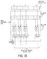
- Figure 13 is a block diagram of a hardware implementation of a portion of
the backpressure logic according to one embodiment of the present invention.
-
Detailed Description Of The Invention
-
A method and apparatus are described for scheduling unicast and multicast
traffic in an input-queued network device. In the following description, for the
purposes of explanation, numerous specific details are set forth in order to provide
a thorough understanding of the present invention. It will be apparent, however, to
one skilled in the art that the present invention may be practiced without some of
these specific details. In other instances, well-known structures and devices are
shown in block diagram form.
-
The present invention includes various steps, which will be described below.
The steps of the present invention may be performed by hardware components or
may be embodied in machine-executable instructions, which may be used to cause
a general-purpose or special-purpose processor or logic circuits programmed with
the instructions to perform the steps. Alternatively, the steps may be performed by
a combination of hardware and software.
-
Assuming sufficient processing speed can be made available to
accommodate cell scheduling time constraints, it is envisioned that the present
invention may also be provided as a computer program product which may include
a machine-readable medium having stored thereon instructions which may be used
to program a computer (or other electronic devices) to perform a process according
to the present invention. The machine-readable medium may include, but is not
limited to, floppy diskettes, optical disks, CD-ROMs, and magneto-optical disks,
ROMs, RAMs, EPROMs, EEPROMs, flash memory, magnet or optical cards, or
other type of media / machine-readable medium suitable for storing electronic
instructions. Moreover, the present invention may also be downloaded as a
computer program product, wherein the program may be transferred from a remote
computer (e.g., a server) to a requesting computer (e.g., a client) by way of data
signals embodied in a cater wave or other propagation medium via a
communication link (e.g., a modem or network connection).
-
Importantly, while embodiments of the present invention will be described
with respect to a network device, such as a router, or a Layer 2 or Layer 3 switch
operable within a TCP/IP network, the method and apparatus described herein are
equally applicable to Asynchronous Transfer Mode (ATM) networks and networking
devices, and other devices such as multiprocessing computers, for example.
Additionally, while various embodiments of the present invention are described in
connection with a networking device that recognizes four different classes of
service, the method and apparatus described herein are not limited to such a
configuration.
EXEMPLARY NETWORK DEVICE ARCHITECTURE
-
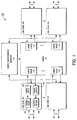
A simplified block diagram illustrating an exemplary network device 100
employing a switched backplane architecture will briefly be described with
reference to Figure 1. According to the embodiment depicted, the network device
100 includes a plurality of line cards 105, a fabric 120, and a fabric configuration
manager 110 (also referred to as the fabric arbiter). Each of the line cards 105 is
coupled to a corresponding fabric interface 115 of the fabric 120. The line cards
105 each include forwarding logic 106, a fabric input 107 (also referred to as an
input port), output scheduling logic 108, and a fabric output 109 (also referred to as
an output port). According to one embodiment, the forwarding logic 106
determines the output port(s) to which received packets need to be forwarded and
performs other Internet Protocol (IP) header processing, such as appending the
next hop Media Access Control (MAC) address retrieved from a forwarding
database (not shown), updating the time-to-live (TTL) field, and calculating a new
header checksum.
-
According to one embodiment, in order to simplify processing throughout the
network device 100, packets are segmented into fixed length cells before being
queued for transfer across the fabric 120 at the fabric input 107. The fabric input
107 may include a set of virtual output queues (VOQs) (not shown) for each class
of service supported. By providing a dedicated queue per fabric input 107 per
class of service, the head-of-line blocking phenomenon experienced in simple input
buffered networking devices that employ a single first-in-first-out (FIFO) queue is
eliminated. The fabric input 107 may also include a dedicated multicast queue (not
shown) for multicast traffic for each class of service.
-
The fabric 120 allows multiple line cards 105 to communicate with each
other simultaneously. According to one embodiment, the fabric 120 comprises a
crossbar switch. Advantageously, since all crossbars are internally non-blocking,
every input and output port is capable of transferring data simultaneously during
each time slot. A crossbar implementation is additionally advantageous due to its
simplicity and its ability to deliver multicast data to multiple outputs simultaneously
by replicating cells within its interconnected fabric.
-
The novel fabric configuration manager 110 is coupled to each line card 105
and the fabric 120. At the beginning of each cell scheduling cycle, through its
interface with the line cards 105, the fabric configuration manager 110 may receive
information regarding the cells that are ready for transmission across the fabric
120. Briefly, the fabric configuration manager 110 is responsible for determining a
conflict-free matching of ports each time slot, configuring the fabric 120 to form
connections between the appropriate fabric interfaces 115, and communicating the
scheduling decisions to the fabric inputs 107. As will be described further below,
the novel fabric configuration manager 110 includes independent unicast and
multicast schedulers that allow flexible scheduling, such as pipelined staging of
multicast and unicast scheduling and programmable multicast scheduling
frequency.
-
The output scheduling logic 108 is coupled to the fabric output 109 to
schedule the time at which cells are reassembled into packets and transmitted on
the output link. In order to meet specific quality of service (QoS) requirements
associated with the classes of service supported, the fabric output 109 may include
a dedicated output queue per class of service.
-
The functional units described above may be implemented separately or in
various combinations in various types of programmable or hardcoded logic, such
as FPGAs, TTL logic, or an application specific integrated circuits (ASICs).
Alternatively, the functional units described above may be implemented with a
processor or other components of a programmed computer that perform a series of
operations dictated by software or firmware, or a combination of hardware and
software or firmware. Importantly, the present invention is not limited to a particular
implementation of these functional units.
Exemplary Fabric Configuration Manager
-
The fabric configuration manager 110 ensures that queue lengths at the
input and output ports are maintained at reasonable levels and that the amount of
delay experienced by packets traversing the network device is low. The fabric
configuration manager 110 seeks to achieve these goals by providing ample
service bandwidth to all pods. Responsive to transmission requests received from
the input ports 107, the fabric configuration manager 110 provides each of the
input ports 107 with an equal opportunity to transfer cells to desired output ports
109. Additionally, the fabric configuration manager 110 employs a novel
mechanism to combine multicast and unicast scheduling cycles which allows
variable rate multicast servicing to be achieved while supplying both types of traffic
with fair access to the fabric 120.
-
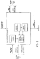
Referring now to Figure 2, various functional units will now be described that
may be employed in the fabric configuration manager 110 according to one
embodiment of the present invention. In the embodiment depicted, the fabric
configuration manager 110 includes an input queue status block 205, time slot
scheduling control logic 210, a multicast scheduler 215, and a unicast scheduler
220.
-
The multicast scheduler 215 implements a fabric arbitration algorithm for
multicast cells. The multicast scheduler 215 seeks to provide bounded scheduling
delay and low variability by transferring at least one high priority multicast cell
completely in each multicast scheduling cycle. Importantly, this preference also
simplifies the implementation of the multicast scheduler 215 and takes advantage
of the multicast capability of the fabric 120. Details regarding the implementation
of the multicast scheduler 215 and the processing performed by the multicast
scheduler 215 are described below.
-
The unicast scheduler 220 implements a fabric arbitration algorithm for
unicast cells. In one embodiment, the unicast scheduler 220 operates in
accordance with the iSLIP unicast scheduling algorithm which is described below.
However, in other embodiments, a variety of other unicast scheduling approaches
may be employed such as, Programmable Iterative Matching (PIM), iterative
Longest Queue First (i-LQF), iterative Oldest Cell First (i-OCF) or variants and
combinations thereof.
-
The time slot scheduling control logic 210 initiates multicast and unicast
scheduling during the appropriate scheduling time slots. In one embodiment,
unicast scheduling is performed every time slot while multicast scheduling is
performed every other time slot. In another embodiment, the frequency at which
multicast scheduling is performed is a programmable parameter, e.g., multicast
scheduling frequency 245, that may be provided by the network administrator, for
example. Assuming that a time slot is not long enough to allow both multicast
scheduling and unicast scheduling to be completed if performed sequentially,
according to one embodiment, the scheduling of multicast and unicast cells that are
to be delivered during the same time slot may be staged in a pipelined fashion.
For example, multicast scheduling may be performed in advance of the time slot in
which the results are used. In this manner, during time slots in which only unicast
cells are transferred across the fabric 120, both multicast and unicast scheduling
may be performed independently and in parallel. During time slots in which both
multicast and unicast cells are to be transferred, the results of the multicast
scheduling cycle that were performed in advance are fed into the unicast scheduler
220 and the unicast scheduler 220 then schedules unicast cells whose ports are
not being used by the previously scheduled multicast cells. Importantly, while
specific multicast and unicast scheduling approaches are described herein, the
mechanism for producing a combined schedule is not limited to these particular
approaches. The novel separation and pipelined staging of multicast and unicast
scheduling and the parallel operation of the multicast and unicast scheduling that
will be described further below are equally applicable to other current and future
scheduling approaches.
-
In the embodiment depicted, the fabric configuration manager 110 has
control information interfaces with the input ports 107, the output ports 109, and the
fabric 120.
-
Control information generated by the fabric configuration manager 110
includes information regarding queue selection 240 and 255 which is sent each
time slot to those of the input ports and output ports participating in the schedule
generated by the multicast scheduler 215 and/or the unicast scheduler 220.
Additionally, each time slot, the fabric configuration manager 110 produces a fabric
configuration 260 based upon the current schedule. The fabric configuration 260 is
communicated to the fabric 120 each time slot to activate the fabric 120 and cause
the fabric 120 to form appropriate connections among the fabric interfaces 115 to
accommodate the current schedule.
-
In this example, control information received by the fabric configuration
manager 110 from the input ports 107 includes input queue state information 230
and transmit requests 235. According to one embodiment, input queue state
information 230 comprises information on newly received cells such as an
indication of the queue with which the cell is associated (identified by the port and
the class of service, for example) and the output port(s) to which the cell is
destined. In this manner, the current state of the queues at each of the input ports
may be maintained in the input queue status block 205. In alternative
embodiments, queue status may be kept at the input ports 107.
Transmit requests 235 may be received from the input ports 107 at the beginning of
each time slot. The transmit requests 235 identify the output port(s), if any, to
which the corresponding input port has a cell ready to be transferred. As will be
described further below, the transmit requests 235 may be presented to one or
both of the multicast scheduler 215 and the unicast scheduler 220 in the form of
request vectors for each output port 109. Each request vector identifies those of
the input ports 107 with requests for a particular output port 109.
-
The fabric configuration manager 110 also receives control information from
the output ports 109. For example, a back pressure signal 250 may identify output
ports 109 having one or more output queues that have exceeded a predetermined
threshold of pending cells. Briefly, in network devices employing "speedup," e.g.,
those operating their fabrics faster than the input and output port capacity, a back
pressure signaling mechanism is important to protect the output ports from excess
traffic from the fabric. In prior architectures, a back pressure signal is typically
coupled directly from each of the output ports 109 to each of the input ports 107.
Typically, output ports assert their back pressure signal upon exceeding a
predetermined threshold of pending cells. Subsequently, when the number of
pending cells falls below another predetermined threshold, the output port
deasserts the back pressure signal. While an output port is back pressuring, input
ports do not transfer cells to that output port. When VOQs are employed at the
input ports 107, back pressure does not cause difficulties for unicast traffic since a
head-of-line unicast cell destined for a back pressuring output only blocks other
cells destined for the same output. However, a complication occurs for multicast
traffic. When a particular output port is back pressuring, a head-of-line multicast
cell blocks the rest of the cells in the multicast queue, which may or may not be
destined for the back pressuring port. The novel back pressure mechanism
described below provides for centralized back pressure handling and solves this
head-of-line blocking problem for multicast traffic.
Multicast Scheduling
-
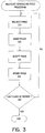
Having described the environment in which the various features of the
present invention may implemented, multicast scheduling cycle processing will now
be described with reference to the flow diagram of Figure 3. Briefly, in the
embodiment illustrated, the multicast scheduling cycle processing is broken down
into four phases: a request phase, a grant phase, an accept phase, and an update
phase. The four phases are repeated sequentially for each class of service in
decreasing order of priority each multicast scheduling cycle. Advantageously,
according to one feature of the present embodiment, only a single scheduling
iteration is performed per class of service, thereby reducing the time required for
multicast scheduling over prior multicast scheduling approaches.
-
At the beginning of each scheduling cycle, all input ports and output ports
are initially unmatched. Only those that remain unmatched at the end of an
iteration are available for matching in the next iteration. The scheduling cycle
begins at step 310 by performing the request phase. During the request phase,
each of the input ports 107 communicates a transmit request 235, in the form of a
bit vector, for example, to the fabric configuration manager 110. Based upon the
transmit requests 235, request vectors are formed for each output port 109. Recall,
each request vector identifies those of the input ports 107 with requests for a
particular output port 109. For purposes of illustration, the transformation of
transmit requests 235 to request vectors may be thought of conceptually as
accumulating transmit requests 235 as columns of a table and subsequently
reading rows of the accumulated information to determine the corresponding
request vectors.
-
At step 320, the grant phase is performed. During the grant phase, the
multicast scheduler 215 evaluates the request vectors for the current class of
service corresponding to those of the output ports that remain available for
matching. The purpose of this evaluation is to determine a conflict-free matching of
input ports 107 and output ports 109. According to one embodiment, in order to
ensure that each of the input ports 107 is provided with fair access to the output
ports 109, a single global indicator that identifies which of the input ports is to
receive priority for the current scheduling cycle is maintained for each class of
service. In one embodiment, this priority indicator comprises a modulo N counter,
referred to as the global multicast round robin counter (GRRC), where N
represents the number of ports. In this example, evaluating request vectors
involves searching the request vector in a circular fashion starting from the input
port 107 identified by the GRRC for the appropriate class of service. The first input
port 107 in the request vector that has a request for the output port 109, and is
available for matching is selected to receive access to the output port 109. Finally,
after the request vectors for the current class of service have been evaluated,
those of the output ports 109 that were matched during the current iteration should
be marked as unavailable. In this manner, the matched output ports 109 are
removed from further consideration in subsequent iterations of the scheduling
cycle.
-
At step 330, the accept phase is performed. Since multicast cells may be
destined for more than one output port 109, input pods 107 may receive grants
from multiple output ports 109. During the accept phase, regardless of the number
received, each input port 107 accepts all grants. This manner of acceptance
expresses the multicast algorithm's preference for completely transferring at least
one high priority multicast cell across the fabric 120 during each multicast
scheduling cycle. Additionally, by accepting all grants, the multicast capability of
the fabric 120 is utilized to perform cell replication. Finally, those of the input ports
107 that were matched during the current iteration should be marked as
unavailable. In this manner, the matched input ports 107 are removed from further
consideration in subsequent iterations of the scheduling cycle.
-
At step 340, the update phase is performed. During the update phase, the
priority indicator, e.g., the GRRC, for the current class of service is incremented to
point to the next input port that has a non-fully-granted request if any of the
following criterion are met:
The cell at the head of the multicast queue associated with the input port identified
by the priority indicator has been sent to all output ports to which it is destined,
No cells are pending on the multicast queue, or
One or more of the output ports to which the cell is destined was unavailable for
matching during the scheduling cycle due to back pressure.
-
Importantly, the priority indicator for the highest priority class of service will
always be incremented, since one of the above criteria will always be true for this
class of service. Additionally, it should be noted that as a result of the processing
described above, "fanout-splitting" is supported. If any of the output ports 109 that
has a request from the input port 107 pointed to by the priority indicator is
unavailable, the cell is partially delivered to those of the output ports 109 that are
available. Therefore, a cell may be transferred to the output ports 109 to which it is
destined over a number of scheduling cycles.
-
The update phase may also include updating the request vectors for use in
the next iteration. In one embodiment, the request vectors may be modified based
upon the accepts such that no requests will be presented in subsequent iterations
from an input port that has accepted an output port and/or such that no requests
will be presented to an output port that has been accepted by an in put port.
At step 350, it is determined if the last class of service has been scheduled. If not,
processing continues with step 310 for the next class of service. Otherwise, if the
last class of service has been scheduled, then the multicast scheduling cycle is
complete.
-
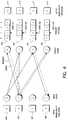
Referring now to Figure 4, one iteration of an exemplary multicast
scheduling cycle will be described. Communication of transmit request information
is depicted as a solid line from an input port to an output port and grants are
depicted as dotted lines from output ports to input ports. According to this
example, there are four input ports numbered 0 to 3 and four output ports
numbered 0 to 3. The input ports each have a corresponding unavailability
indicator 405-408. Similarly, each output port has a corresponding unavailability
indicator 415-418. In this example, the global priority indicator comprises a GRRC
450 which currently points to input port 1. Therefore, input port 1 will receive
priority over the other input ports during this scheduling cycle.
-
In this example, input port 0 has a multicast cell ready for delivery to output
ports 1 and 2, the head-of-line multicast cell at input port 1 is destined for output
ports 0, 1 and 3, no multicast cells are pending at input port 2, and input port 3 has
a multicast cell that is ready to be transferred to output port 2. While, in reality, this
control information is communicated from the input ports 107 to the fabric
configuration manager 110, for purposes of this example, the communication is
conceptually represented as being communicated between input ports 0-3 and
output ports 0-3. At any rate, during the request phase (step 310) the input ports
each communicate their transmit request information to the output ports.
The transmit request information accumulated at output port 0 forms request vector
425. Similarly, request vectors 426-428 are formed at output ports 1-3,
respectively. The request vectors 425-428 have a bit position corresponding to
each of the input ports 0-3. A bit is set in the request vectors 435-428 when the
corresponding input port has a multicast cell ready for delivery to the output port.
The bit remains clear if the corresponding input port has no cell destined for the
output port.
-
During the grant phase (step 320), each output port that is available
searches its corresponding request vector 425-428, respectively, in a circular
fashion beginning with the input port identified by GRRC 450 to select the first
available input port 0-3 that has a request for that output port. In this example, the
first available input port that has a request for output port 0 is input port 1. Input
port 1 is also the first available input port that has a request for output port 1.
Output port 2 selects input port 3 and output port 3 selects input port 1. After the
output ports have selected an input port, grants are issued to those of the input
ports that have been selected and those of the output ports that gave a grant to an
input port set their corresponding unavailability indicators. In this example,
therefore, all of the output ports would set their output unavailability indicators 415-418.
-
During the accept phase (step 330), each input port accepts all grants
received and each input port that received at least one grant sets its input
unavailability indicator 405-408. In this example, input ports 1 and 3 would set
their corresponding unavailability indicators. Therefore, input ports 1 and 3 would
not participate in subsequent iterations until a new scheduling cycle begins.
-
During the update phase (step 340), the GRRC update criteria are evaluated
and the GRRC 450 is incremented to point to input port 2. Therefore, in the next
scheduling cycle, input port 2 will receive priority over input ports 0, 1 and 3.
-
Assuming the fabric 120 were configured according to this scheduling cycle
iteration, the multicast cell from input port 3 would be delivered to output port 2 and
the multicast cell from input port 1 would be delivered to output ports 0, 1 and 3.
-
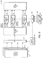
Figure 5 is a high level block diagram of a hardware implementation of a
multicast scheduler according to one embodiment of the present invention.
According to this embodiment, the multicast scheduler 500 consists of a set of
priority request vector registers for each class of service 510-513, a multiplexer
(MUX) 520, iteration control logic 530, a set of active request vector registers 540,
a set of output grant arbiters 550, a set of priority indicators, e.g., GRRCs 580-583,
a MUX 560, and a set of grant vector registers 570.
-
During a multicast scheduling cycle, iteration control logic 530 causes an
arbitration iteration to be performed for each class of service. The priority request
vector registers 510-513 are coupled to the input of MUX 520. Iteration control
logic 530 is coupled to MUX 520 to select the set of priority request vectors for the
current iteration. The output of MUX 520 is coupled to the set of active request
vector registers 540. As a result, the priority request vectors selected for the
current iteration are passed to the active request vector registers 540. Iteration
control logic 530 is also coupled to MUX 560 to select the GRRC appropriate for
the current iteration. The GRRCs 580-583 are coupled to the input of MUX 560
and the output of MUX 560 is coupled to each of the output grant arbiters 55,
thereby programming each output grant arbiter 550 with the selected GRRC.
-
The active request vector registers 540 are coupled to the output grant
arbiters 550. Each of the output grant arbiters 550 are presented with priorities
and a request vector from the active request vector registers 540. For example,
output grant arbiter 0 receives request vector 541 which indicates which of the
input ports have a request for output port 0 and identifies the priorities associated
with each of the requests. Similarly, output grant arbiters 1 and N receive request
vectors 542 and 543, respectively and the associated priorities.
-
Each output grant arbiter 550 looks at the inputs associated with the class of
service selected for the current iteration and selects one request on behalf of the
corresponding output port. According to one embodiment, the output grant arbiters
550 select the request closest in priority to the GRRC in a circular fashion. A
vector identifying the selected and non-selected input ports is then stored in the
grant vector registers 570. Once an output grant arbiter 550 has matched an input
port to its corresponding output port, it is disabled in all further iterations of the
multicast scheduling cycle in order to prevent the output grant arbiter 550 from
making additional matches.
Unicast Scheduling
-
Having described an exemplary hardware implementation of a multicast
scheduler and exemplary multicast scheduling processing, unicast scheduling
cycle processing will now be described with reference to the flow diagram of Figure
6.
-
Briefly, in the embodiment illustrated, in a manner similar to multicast
scheduling cycle processing, the unicast scheduling cycle processing is
conceptually divided into four phases: a request phase, a grant phase, an accept
phase, and an update phase. The four phases may be repeated for multiple
iterations until no further port matchings can be established or until the time
allocated to unicast scheduling has expired. Each iteration seeks to identify one or
more port matchings that were not made in earlier iterations. The unicast algorithm
is similar to the multicast algorithm, but it is more complicated due to the fact that
there can be contention among two or more queues on the input side. For
example, as with multicast, an input may receive grants from multiple outputs.
However, in the unicast case, an input can be paired with only one output and can
therefore accept only one of the grants received.
-
As above, at the beginning of each scheduling cycle, all input ports and
output ports are initially unmatched (an exception will be noted below with regard
to the novel combination of multicast and unicast scheduling). Only those that
remain unmatched at the end of an iteration are available for matching in the next
iteration. The unicast scheduling cycle begins at step 610 by performing the
request phase. During the request phase, each of the input ports 107
communicates a transmit request 235 to the fabric configuration manager 110
indicating the output ports 109 to which cells at the head of its VOQs are destined.
Based upon the transmit requests 235, request vectors are formed for each output
pod 109 that identify those of the input ports 107 with requests for the output port
109.
-
At step 620, the grant phase is performed. According to one embodiment, in
order to ensure that each of the input ports 107 is provided with fair access to the
output ports 109, a per output port priority indicator is maintained for each class of
service. The priority indicator identifies which of the input ports receives top
priority to the output port for the current scheduling iteration. In one embodiment,
the priority indicators are modulo N counters, referred to as output round robin
counters (ORRCs), where N represents the number of ports. In any event, during
the grant phase, the unicast scheduler 220 evaluates the request vectors for each
output port in a parallel fashion. If the output port is available for matching with an
input port, then the request vectors for each class of service are evaluated to
determine to which input port a grant will be made. The evaluation begins with the
input port pointed to by the corresponding ORRC and proceeds in a circular
fashion until an available input port is found that has a request for the output port.
Importantly, because each class of service is independent, the operations for each
class of service may be performed in parallel. However, if two input ports are
selected for matching with an output port, then the input port selected from the
request vector corresponding to the higher priority class of service receives the
grant over the input port selected from the request vector corresponding to the
lower priority class of service. At any rate, based upon the results of the evaluation
of the request vectors, grants are made to the selected inputs forming a grant
vector for each input port indicating the output ports 109 that have granted a
request from the input port 107.
-
At step 630, the accept phase is performed. Since two or more VOQs may
have a head of line cell pending for different output ports 109, input ports 107 may
receive grants from multiple output ports 109. During the accept phase, the unicast
scheduler 220 evaluates the grant vectors for each input port that is available for
matching with an output port (in parallel) and accepts only one grant per available
input port. According to one embodiment, a per input port priority indicator is
maintained for each class of service. The priority indicator identifies which of the
output ports that is given top priority by the input port for the current scheduling
iteration. In one embodiment, the priority indicators are modulo N counters,
referred to as input round robin counters (IRRCs), where N represents the number
of ports. In any event, in order to accomplish the evaluation of a grant vector, the
unicast scheduler 220 begins with the output port pointed to by the corresponding
IRRC and proceeds in a circular fashion until an available output port is found that
has issued a grant to the input port. As above, because each class of service is
independent, the operations for each class of service may be performed in parallel.
Should more than one output port be selected for matching with an input port, then
the output port selected from the grant vector corresponding to the higher priority
class of service is accepted. Based upon the results of the evaluation of the grant
vectors, accepts are made to the selected outputs. Finally, those of the input ports
107 and output ports 109 that were matched during the current iteration (as
determined by the accepts) should be marked as unavailable. In this manner, the
matched ports are removed from further consideration in subsequent iterations of
the scheduling cycle.
-
At step 640, the update phase is performed. The update phase includes
updating the request vectors for use in the next iteration and updating the priority
indicators, e.g., the ORRC values and the IRRC values. In one embodiment, the
request vectors may be modified based upon the accepts such that no requests will
be presented in subsequent iterations from an input port that has accepted an
output port and/or such that no requests will be presented to an output port that
has been accepted by an input port. With regard to update of the priority
indicators, an ORRC is incremented if either the input port to which it points has
been serviced by the corresponding output port (e.g., the output port has issued a
grant to the input port which has been accepted for the corresponding class of
service) or the input port requires no service from the output port (e.g., the input
port has no unicast cells pending for the corresponding output port at the
corresponding class of service). Similarly, an IRRC is incremented if either the
output port to which it points has been serviced by the corresponding input port
(e.g., the input port has accepted a grant to the output port for the corresponding
class of service) or the output port requires no service from the input port (e.g., the
output port has issued no grant to the corresponding input port for the
corresponding class of service). Importantly, the priority indicators are updated
only after the first iteration of a scheduling cycle.
-
Before discussing the update mechanism further, it may be useful to
describe the overall functioning of the ORRCs and the IRRCs. The ORRCs and
the IRRCs are tools that ensure that the unicast scheduling algorithm works in a
fair manner and that the delays seen by all the input ports are finitely bounded.
Each scheduling cycle, the ORRC for a particular output port steps through the
request vector for the output port until it encounters a request (e.g., the bit it is
pointing to is set indicating the corresponding input port has issued a request to the
output port). The ORRC remains at this value until the request is serviced. This
behavior ensures that the output port will always send a grant to this input port at
every opportunity. Similarly, the IRRC for a particular input port steps through the
corresponding grant vector until it encounters a grant (e.g., the bit it is pointing to is
set indicating the corresponding output port has given a grant to the input port).
The IRRC remains at this value until this grant is accepted. This behavior ensures
that the input port will always accept the grant from this output port at every
opportunity. Without such a gating mechanism, there is no guarantee that a cell
will be transmitted. For example, if an ORRC was allowed to move ahead of a
request without servicing it or if an IRRC was allowed to move ahead of a grant
without servicing it, then the possibility exists that the corresponding cell might
never be transmitted.
-
Returning to the updating of the ORRC and IRRC values, as was mentioned
above, they are incremented only after the first iteration of a scheduling cycle.
Additionally, the priority indicators may be updated differently depending upon the
circumstances. For example, when a port to which a priority indicator points does
not need service, the priority indicator is simply incremented by one (modulo N).
However, when a port to which a priority indicator points needs service, the priority
indicator is only updated after that port has been serviced; otherwise the priority
indicator is not updated. The ORRC and IRRC values are incremented beyond a
port that has just been serviced. For each IRRC, if the corresponding input port
has accepted an output port for the corresponding class of service, then the IRRC
is incremented to point to the output port after the one accepted. That is, the IRRC
is set to one plus the value of the output port accepted (modulo N). Similarly, for
each ORRC, if the corresponding output port has been accepted by an input port
for the corresponding class of service, then the ORRC is set to one plus the value
of the input port that has accepted the output port (module N). In this manner,
connections made in the first iteration are the lowest priority during the next
scheduling cycle and no connections are starved.
-
At step 650, it is determined if this is the last iteration of the scheduling
cycle. For example, a predetermined number of iterations may be performed or the
iterations may continue so long as at least one port matching was made during the
previous iteration. In any event, the number of iterations need not exceed the
number of input ports, N, since only one connection can be made for each input
port. If this is not the last iteration of the scheduling cycle, processing continues
with step 610. Otherwise, the unicast scheduling cycle is complete and fabric
configuration may commence at step 660.
-
At step 660, fabric configuration is performed. The fabric 120 is configured
one time for each unicast scheduling cycle after the current schedule, e.g., the port
matchings, has been established. Based upon the state of the accept signals at
the conclusion of the unicast scheduling cycle, the unicast scheduler 220 presents
a fabric configuration 260 to the fabric 120. The fabric configuration 260 activates
the fabric 120 and directs the fabric 120 to form connections among the fabric
interfaces 115 that will accommodate the transfer of cells across the fabric 120
according to the current schedule.
-
Referring to Figures 7A and 7B, one iteration of an exemplary unicast
scheduling cycle will now be described. Beginning with Figure 7A, communication
of transmit request information is depicted as a solid line from an input port to an
output port and grants are depicted as dotted lines from output ports to input ports.
For purposes of this example, four input ports numbered 0 to 3 and four output
ports numbered 0 to 3 are depicted. The input ports each have a corresponding
unavailability indicator 705-708. Similarly, each output port has a corresponding
unavailability indicator 715-718. In this example, the output ports each have a
corresponding priority indicator, ORRC 0-3, shown pointing to input ports 1, 3, 2,
and 0, respectively. Therefore, during this scheduling cycle, input port 1 receives
priority over any other input ports contending for output port 0, input port 3 receives
priority over any other input ports contending for output port 1, input port 2 receives
priority over any other input ports contending for output port 2, and input port 0
receives priority over any other input ports contending for output port 3.
-
In this example, input port 0 has two unicast cells ready for transfer across
the fabric 120. One is destined for output port 1 and the other is destined for
output port 2. Three head-of-line unicast cells at input port 1 are destined for
output ports 0, 1 and 3. No unicast cells are pending at input port 2. Finally, input
port 3 has one unicast cell that is ready to be transferred to output port 2. While
control information is typically communicated from the input ports 107 to the fabric
configuration manager 110, for purposes of this example, the communication is
conceptually represented as being communicated between input ports 0-3 and
output ports 0-3. At any rate, during the request phase (step 610) the input ports
each communicate their transmit request information to the output ports.
The transmit request information accumulated at output port 0 forms request vector
725. Similarly, request vectors 726-728 are formed at output ports 1-3,
respectively. The request vectors 725-728 have a bit position corresponding to
each of the input ports 0-3. Again, a bit is set in the request vectors 735-728 when
the corresponding input port has a unicast cell ready for delivery to the output port.
The bit remains clear if the corresponding input port has no unicast cells destined
for the output port.
-
During the grant phase (step 620), each output port that is available
searches its corresponding request vector 725-728, respectively, in a circular
fashion beginning with the input port identified by the associated ORRC 0-3 to
select the first available input port that has a request for that output port. In this
example, the first available input port that has a request for output port 0 is input
port 1. Input port 0 is the first available input port that has a request for output port
1. Output port 2 selects input port 3 and output port 3 selects input port 1. After
the output ports have selected an input port, grants are issued to those of the input
ports that have been selected. In this example, therefore, grants are issued from
output port 0 to input port 1, from output port 1 to input port 0, from output port 2 to
input port 3, and from output port 3 to input port 1.
-
Turning now to Figure 7B, continuing with the present example, a grant is
depicted as a dotted line from an output port to an input port and accepts are
depicted as solid lines from input ports to output ports. For purposes of arbitrating
among multiple grants, each input port has a corresponding priority indicator, IRRC
0-3, shown pointing to output ports 1, 3, 2, and 0, respectively. Therefore, during
this scheduling cycle, output port 1 receives priority over any other output ports
contending for input port 0, output port 3 receives priority over any other output
ports contending for input port 1, output port 2 receives priority over any other
output ports contending for input port 2, and output port 0 receives priority over any
other output ports contending for input port 3.
-
During the accept phase (step 630), each input port that is available
searches its corresponding grant vector 735-738, respectively, in a circular fashion
beginning with the output port identified by the associated IRRC 0-3 to select the
first available output port that has a grant for that input port. In this example, the
first available output port that has a grant for input port 0 is output port 1. Output
port 3 is the first available output pod that has a request for input port 1. Input pod
2 has received no grants and input port 3 selects output port 2. After the input
ports have selected an output port, accepts are issued to those of the output ports
that have been selected. In this example, therefore, accepts are issued from input
port 0 to output port 1, from input port 1 to output port 3, and from input port 3 to
input port 2. Finally, those of the input ports and output ports that were matched
(e.g., those of input ports issuing accepts and those of the output ports receiving
accepts) are marked as unavailable. In this example, therefore, input ports 0, 1,
and 3 and output ports 1-3 are marked as unavailable by setting input unavailability
indicators 705, 706, and 708 and output unavailability indicators 716-718,
respectively, thereby removing these ports from consideration in subsequent
iterations of the scheduling cycle.
-
During the update phase (step 640), the IRRCs and the ORRCs are updated
in accordance with the update mechanism described above. In this example, the
value of ORRC0 will remain unchanged since a request from the input port to which
it points remains unserviced. The value of ORRC1 will be updated to one since the
request from input port 0 was serviced. The value of ORRC2 will be updated to
zero since the request from input port 3 was serviced. The value of ORRC3 will be
updated to two since the request from input port 1 was serviced. Meanwhile, on
the input side, the value of IRRC0 will be updated to two, the value of IRRC1 will be
updated to zero, and the values of both IRRC2 and IRRC3 will be updated to three.
Assuming the fabric 120 were configured according to this exemplary scheduling
cycle iteration, the fabric configuration would cause a unicast cell to be transferred
from input ports 0, 1, and 3 to output ports 1, 3, and 2, respectively.
-
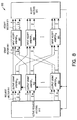
Figure 8 is a high level block diagram of a hardware implementation of a
unicast scheduler according to one embodiment of the present invention. For
purposes of simplifying the discussion, this example addresses the case of a
unicast scheduler 800 that supports a single class of service. According to this
embodiment, the unicast scheduler 800 consists of a set of active request vector
registers 810, a set of output grant arbiters 850, a set of input accept arbiters 860,
and a set of accept vector registers 870.
-
The active request vector registers 810 are coupled to the output grant
arbiters 850. The output grant arbiters 850 choose among contenting requests on
behalf of the corresponding output port 109. At the beginning of each unicast
scheduling cycle, transmit requests 235 from the input ports 107 are loaded into
the active request vector registers 810. Each iteration of the scheduling cycle, N-bit
request vectors 811 are presented to each of the N corresponding output grant
arbiters 850.
-
Each of the output grant arbiters 850 are coupled to each of the input accept
arbiters 860. The output grant arbiters 850 each select one of the competing
requests that is closest in priority to its ORRC and issue a grant signal to the input
accept arbiter 860 corresponding to the selected request.
-
The input accept arbiters 860 are coupled to the set of accept vector
registers 870 to identify the output port that has been matched with the
corresponding input port. The input grant arbiters 860 each select one of the
competing grants received from the output grant arbiters 850 that is closest in
priority to its IRRC and issue an accept signal corresponding to the selected output
port. The input accept arbiters 860 present accept signals in the form of an accept
vector 871 to the set of accept vector registers 870. Each iteration, feedback from
the accept vector registers 870 may be used to mask oft requests corresponding to
ports that have already been matched during the scheduling cycle. Alternatively,
once a port has been matched, the corresponding arbiter 850 or 860 may be
disabled in all further iterations of the scheduling cycle in order to prevent the
arbiter from making additional matches. At any rate, the accept signals are
accumulated in the set of accept vector registers 870 during each iteration of the
unicast scheduling cycle and, as discussed above, are used at the end of the
unicast scheduling cycle to configure the fabric 120.
Exemplary Round-Robin Arbiters
-
Figures 9A and 9B depict exemplary round-robin arbiters that may be used
in accordance with one embodiment of the present invention. Referring first to
Figure 9A, an output grant arbiter 950 that understands four classes of service is
illustrated. In this example, the output grant arbiter 950 includes a grant priority
filter 905 and a programmable priority encoder 920. A plurality of request vectors
904 associated with one or more priority levels are received by the grant priority
filter 905. The grant priority filter 905 selects the request vector associated with
the highest priority class of service and allows those requests 915 to be presented
to the programmable priority encoder 920. As is well known, programmable priority
encoders select as an output one of its inputs as determined by a supplied priority
indication. In this example, the programmable priority encoder 920 grants one of
the requests 915 based upon the highest priority 910, e.g., an ORRC, supplied by
the grant priority filter 905. The priority levels and the grants produced by N output
grant arbiters 950 are presented to an input accept arbiter 990 such as that
illustrated in Figure 9B. In this example, the input accept arbiter 990 includes an
accept priority filter 945 and a programmable priority encoder 960. The accept
priority filter 945 outputs the grants 955 associated with the highest priority class of
service level. The programmable priority encoder 960 accepts one of the grants
955 based upon the highest priority 951, e.g., an IRRC, supplied by the accept
priority filter 945.
-
In one embodiment, the unicast scheduler 220 may include N output grant
arbiters 950 and N input accept arbiters 990. Importantly, however, the present
invention is not limited to any particular round-robin arbiter, the multicast scheduler
215 and unicast scheduler 220 may employ various other types of round-robin
arbiters. For example, one of the fast programmable priority encoders described in
P. Gupta and N. McKeown, "Design and Implementation of a Fast Crossbar
Scheduler," Hot Interconnects VI, Stanford University, August 1998, which is
hereby incorporated by reference, may be used.
Combined Multicast and Unicast Scheduling
-
According to one embodiment of the present invention, a novel scheduling
approach permits unicast scheduling processing and multicast scheduling
processing to operate in parallel and independently resulting in a combined
schedule comprising both unicast and multicast cells. Parallelism may be
achieved, for example, by pipeline staging of unicast and multicast scheduling.
Pipelining unicast and multicast scheduling is advantageous, for example, if the
duration of the cell scheduling cycle is insufficient to accommodate both unicast
and multicast scheduling in serial. Prior scheduling approaches produce uniform
schedules that are limited to either all unicast cells or all multicast cells. In
contrast, the novel combined scheduling approach permits a combined schedule to
be produced comprising both unicast and multicast cells. In this manner, both
multicast and unicast cells may be transferred across the fabric 120 during the
same time slot. Additionally, the separation of unicast and multicast scheduling
results in increased flexibility and programmability of the rate at which unicast
and/or multicast traffic is serviced.
-
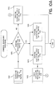
Referring now to Figure 10A, a general flow diagram is described illustrating
combined scheduling processing for two different types of traffic according to one
embodiment of the present invention. This example assumes cell scheduling
processing is performed once each time slot, cell scheduling for one of the types of
traffic, i.e., the first traffic type, is performed less than every time slot, cell
scheduling for the other type of traffic, i.e., the second traffic type is performed
every time slot, cells of the first traffic type are scheduled at least one time slot in
advance of their transfer across the fabric 120, cells of the second traffic type are
scheduled and transferred in the same time slot, and when both cells of the first
and second traffic type.
-
According to this example, at step 1005, a determination is made whether or
not to perform scheduling for the first type of traffic based upon a predetermined
scheduling frequency 1001. The scheduling frequency 1001 may be a hardcoded
value or a programmable parameter as will be discussed further below. At any
rate, if cell scheduling is to be performed for the first type of traffic during the
current time slot, then processing continues with steps 1015 and 1020. Steps 1015
and 1020 are preferably performed by separate and independent cell scheduling
units, as discussed above, thereby providing the ability to perform the cell
scheduling for the two types of traffic in parallel. At step 1020, a cell scheduling
cycle for the first type of traffic is performed and the results are stored for a
subsequent time slot. Concurrently, in step 1015 a cell scheduling cycle for the
second type of traffic is performed for the current time slot. During time slots in
which both the cells of the first and second type of traffic are to be transferred, the
prior scheduling results for the first type of traffic 1002 are fed into the scheduling
processing for the second type of traffic (step 1015) and the scheduler schedules
cells of the second type of traffic whose ports are not being used by the previously
scheduled cells of the first type of traffic. When both scheduling cycles have been
finalized, the combined scheduling processing is complete.
-
Returning to step 1005, if cell scheduling is not to be performed for the first
type of traffic during the current time slot, then processing continues with step
1010. In step 1010, a cell scheduling cycle for the second type of traffic is
performed for the current time slot. As above, during time slots in which both the
cells of the first and second type of traffic are to be transferred, the prior scheduling
results for the first type of traffic 1002 are fed into the scheduling processing for the
second type of traffic (step 1010) and the scheduler schedules cells of the second
type of traffic whose ports are not being used by the previously scheduled cells of
the first type of traffic. When the scheduling cycle has been finalized, the
combined scheduling processing is complete.
-
In alternative embodiments, if the duration of the time slot is greater than or
equal to the time required to perform both scheduling cycles without overlap, then
the cell scheduling cycles may be performed serially. Additionally, in alternative
embodiments, scheduling frequencies may be supplied for both the first type and
the second type of traffic.
-
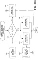
Figure 10B is a flow diagram illustrating an embodiment of Figure 10A in
which unicast and multicast scheduling may be combined. In the embodiment
depicted, multicast and unicast cell scheduling operate separately and
independently, however during selected time slots when both multicast traffic and
unicast traffic are scheduled for transfer across the fabric 120, unicast cells are
scheduled based upon the results of an earlier multicast scheduling cycle. For
example, unicast cells may be scheduled at a lower priority than the multicast cells
by limiting the ports available to the unicast scheduler 220 to those ports that are
left unmatched by the earlier multicast scheduling cycle.
-
At step 1025, a determination is made whether or not to perform multicast
scheduling based upon a predetermined multicast scheduling frequency 1003. If
multicast scheduling is to be performed during the current time slot, then
processing continues with steps 1035 and 1040. Steps 1035 and 1040 are
preferably performed by separate and independent schedulers, such as unicast
scheduler 220 and multicast scheduler 215 discussed above, thereby providing the
ability to perform the multicast and unicast scheduling in parallel. At step 1040, a
multicast scheduling cycle is performed and the results are stored for a subsequent
time slot. Concurrently, in step 1035 a unicast scheduling cycle is performed for
the current time slot. If both unicast and multicast cells are to be transferred during
the current time slot, then the prior multicast scheduling results 1004 are input into
the unicast scheduling processing (step 1035) and the unicast scheduler 220
schedules unicast cells whose ports are not being used by the previously
scheduled multicast cells. When both scheduling cycles have been finalized, the
combined scheduling processing is complete.
-
Returning to step 1025, if multicast scheduling is not to be performed during
the current time slot, then processing continues with step 1030. In step 1030, a
unicast scheduling cycle is performed for the current time slot. Again, if both
unicast and multicast cells are to be transferred during the current time slot, then
the prior multicast scheduling results 1004 are input into the unicast scheduling
processing (step 1030) and the unicast scheduler 220 schedules unicast cells
whose ports are not being used by the previously scheduled multicast cells. When
the scheduling cycle has been finalized, the combined scheduling processing is
complete.
-
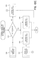
Figure 10C is a flow diagram illustrating another embodiment of Figure 10A
in which unicast and multicast scheduling may be combined. In this embodiment,
multicast and unicast cell scheduling operate separately and independently as
above, however when both multicast traffic and unicast traffic are scheduled for
transfer across the fabric 120, multicast cells are scheduled based upon the results
of an earlier unicast scheduling cycle. For example, multicast cells may be
scheduled at a lower priority than the unicast cells by limiting the ports available to
the multicast scheduler 215 to those ports left unmatched by the earlier multicast
schedule.
-
At step 1045, a determination is made whether or not to perform unicast
scheduling based upon a predetermined unicast scheduling frequency 1006. If
unicast scheduling is to be performed during the current time slot, then processing
continues with steps 1055 and 1060. Steps 1055 and 1060 are preferably
performed by separate and independent schedulers, such as multicast scheduler
215 and unicast scheduler 220 discussed above, thereby providing the ability to
perform the multicast and unicast scheduling in parallel. At step 1060, a unicast
scheduling cycle is performed and the results are stored for a subsequent time slot.
Concurrently, in step 1055 a multicast scheduling cycle is performed for the current
time slot. If both unicast and multicast cells are to be transferred during the current
time slot, then the prior unicast scheduling results 1007 are input into the multicast
scheduling processing (step 1055) and the multicast scheduler 215 schedules
multicast cells whose ports are not being used by the previously scheduled unicast
cells. When both scheduling cycles have been finalized, the combined scheduling
processing is complete.
-
Returning to step 1045, if unicast scheduling is not to be performed during
the current time slot, then processing continues with step 1050. In step 1050, a
multicast scheduling cycle is performed for the current time slot. Again, if both
unicast and multicast cells are to be transferred during the current time slot, then
the prior unicast scheduling results 1007 are input into the multicast scheduling
processing (step 1050) and the multicast scheduler 215 schedules multicast cells
whose ports are not being used by the previously scheduled unicast cells. When
the scheduling cycle has been finalized, the combined scheduling processing is
complete.
Pipelined Staging of Multicast and Unicast Scheduling
-
Figure 11A conceptually illustrates a pipelined approach for scheduling
multicast and unicast traffic according to one embodiment of the present invention.
Multicast scheduling 1100 is shown along the top row. Unicast scheduling 1110 is
shown along the middle row. The bottom row indicates the resulting combined
schedule 1120. The hollow arrows point in the direction of the time slot during
which the resulting schedule is used. For example, multicast schedule M0 is
generated during time slot t0, but is used during time slot t1.
A multicast scheduling frequency register 1003 identifies those of the time slots,
e.g., t0 - t7, during which multicast scheduling 1100 is to be performed. Many
possible implementations of the multicast scheduling frequency register 1003 have
been contemplated. According to one embodiment, a circular register is
implemented, where the bits of the register are set to '1' or '0' in accordance with
whether the current time slot is a multicast time slot. Each time slot, the bits of the
register are rotated and the LSB or the MSB can be evaluated. Alternatively, the
multicast scheduling frequency register 1003 may be implemented as an up or a
down circular counter. Each time slot, the counter is incremented or decremented
and the value in the counter is compared to a predetermined value that indicates
when multicast scheduling is to be performed. According to one embodiment, the
multicast scheduling frequency register 1003 contains a hardcoded value. In
alternative embodiments, however, the multicast scheduling frequency register
1003 is a programmable parameter thereby allowing the provision of variable rate
multicast servicing and putting a cap on the total bandwidth available to multicast
traffic. Responsive to historical network usage or scheduled network usage, the
multicast scheduling frequency register 1003 may be adjusted upward or downward
automatically by a traffic monitoring process, for example. Alternatively, bandwidth
may be allocated between unicast and multicast traffic by the network administrator
by tuning the multicast scheduling frequency.
-
In the example illustrated by Figure 11A, if a bit position in the multicast
scheduling frequency register 1003 contains a '1,' then multicast scheduling 1100
is performed during the corresponding time slot; otherwise no multicast scheduling
is performed during the time slot. According to the embodiment depicted, unicast
scheduling 1110 is performed every time slot. Assuming the duration of a time slot
is insufficient to accommodate both unicast and multicast scheduling in serial, the
novel combined scheduling approach described herein permits a combined
schedule 1120 to be generated by employing a pipelined scheduling approach.
Briefly, in this example, multicast scheduling time slots occur as a subset of unicast
scheduling time slots. Unicast scheduling 1110 occurs every time slot and
multicast scheduling 1100 occurs every other time slot. During the first time slot, t0,
both multicast scheduling and unicast scheduling are performed in parallel. The
multicast scheduling cycle produces a first multicast schedule, M0, for the next time
slot, t1, and the unicast scheduling cycle produces a first unicast schedule, U0, for
the current time slot, t0. Since no multicast cells are scheduled for t0, the resulting
combined schedule is U0.
-
Referring now to the next time slot, t1, no multicast scheduling is performed,
but the results of the previous multicast scheduling cycle, M0, are fed into the
unicast scheduling cycle. As a result, only those ports that are left unclaimed by
M0 are available for use by the unicast scheduling. The resulting unicast schedule,
U1, is therefore limited to filling in ports that were not matched during the earlier
multicast scheduling cycle. In this manner, when both unicast and multicast cells
are to be transferred during the same time slot, unicast cells are effectively treated
as a lower priority than the previously scheduled multicast cells. Cell scheduling
proceeds in a similar manner for the remaining time slots.
-
In alternative embodiments, multicast scheduling may be triggered
differently than as described above. Bit positions in the multicast scheduling
frequency register 1003 containing a '0' may cause multicast scheduling to be
performed in the corresponding time slot while a '1' may inhibit multicast
scheduling. Alternatively, as mentioned above, multicast scheduling may be
triggered by a circular counter. For example, when the counter is incremented or
decremented to a predetermined value this event may cause a multicast
scheduling cycle to be performed. Additionally, in alternative embodiments,
multicast scheduling may be performed more than one time slot in advance of its
use. Further, while an eight bit register is depicted for purposes of illustration,
registers of more or fewer bits may be used depending upon the needs of a
particular implementation. Finally, although the examples only show control of
multicast traffic, it is contemplated that the scheduling of unicast traffic may be
similarly triggered (in addition to or instead of multicast traffic triggering) by
employing a unicast scheduling frequency register (not shown).
-
Turning now to Figure 11B, a pipelined approach for scheduling multicast
and unicast traffic according to another embodiment of the present invention is
conceptually illustrated. As in the previous example, unicast scheduling 1110 is
performed during every time slot and if a bit position in the multicast scheduling
frequency register 1003 contains a '1,' then multicast scheduling 1100 is also
performed during the corresponding time slot; otherwise no multicast scheduling is
performed during the time slot. Also, as above, multicast scheduling time slots
occur as a subset of unicast scheduling time slots. This example illustrates that
multicast scheduling 1110 may be performed more than one time slot in advance of
the use of the resulting schedule. Additionally, multicast scheduling 1110 need not
be symmetric or uniformly distributed. For example, multicast scheduling 1110 is
not limited to being performed every other time slot as shown in Figure 11A.
Rather, if desired, multicast scheduling 1110 may be performed during two or more
consecutive time slots, so long as during at least one time slot unicast traffic is
given priority to ensure unicast traffic has adequate access to the fabric 120.
-
According to this example, during the first time slot, t0, both multicast
scheduling and unicast scheduling are performed in parallel. The multicast
scheduling cycle produces a first multicast schedule, M0, for use in time slot, t2, and
the unicast scheduling cycle produces a first unicast schedule, U0, for the current
time slot, t0. Since no multicast cells are scheduled for t0, the resulting combined
schedule is U0. Multicast scheduling is performed for time slot t3 during time slot,
t1. Again, since no multicast cells are scheduled for t1, the resulting combined
schedule is U1. The unicast scheduling cycle performed during time slot t2 is
dependent upon the results of the previous multicast scheduling cycle, M0 thereby
giving the previously scheduled multicast cells priority over the unicast cells for the
current time slot. Cell scheduling proceeds in a similar manner for the remaining
time slots.
Back Pressure Handling
-
Because a head-of-line multicast cell can block the rest of the cells in the
multicast queue, even though they are headed for different output ports, special
handling of output port backpressure signals is needed to avoid the head-of-line
blocking problem for multicast traffic to protect multicast performance. As
described above, prior architectures typically backpressure the input ports directly
from each of the output ports. Thus requiring knowledge / logic for backpressure
handling at each of the input ports. In contrast, according to one embodiment of
the present invention, the output ports 109, backpressure the fabric arbiter 110.
Consequently, knowledge / logic for backpressure handling is centralized within the
fabric arbiter 110 thereby reducing the complexity of the input ports 107.
-
Briefly, according to one embodiment, each time slot, the output ports 109
communicate an N-bit backpressure signal to the fabric arbiter 110 indicating
whether or not one or more of the corresponding output queues has filled up.
Then, the fabric arbiter 110 makes multicast scheduling decisions based upon the
backpressure signal and the status of the multicast queues. According to one
embodiment, the fabric arbiter 110 is configured to operate in one of two modes of
operation with respect to a backpressuring output port. In the first mode of
operation, the fabric arbiter obeys the backpressure signal and does not include
the backpressuring output port in the fabric configuration. In the second mode of
operation, the fabric arbiter solves the head-of-line blocking problem by ignoring
the backpressure signal and causing the head-of-line multicast cells destined for
the backpressuring output port to be transferred to the backpressuring output port
regardless of the backpressure signal. When received by the backpressuring
output port, the head-of-line multicast cell may be accepted if the output port has
room or dropped. In this manner, multicast performance is protected by allowing
the remainder of the multicast cells the opportunity to be transferred. According to
one embodiment, in order to reduce oscillation of the backpressure signals from
time slot to time slot, once a backpressure signal is asserted it is not de-asserted
until a certain amount of time has passed or until a the output queue size has fallen
below a predetermined threshold. For example, de-assertion of the backpressure
signal may be delayed until the backpressuring output queue is half-empty.
-
Figure 12 is a flow diagram illustrating backpressure processing according
to one embodiment of the present invention. At step 1210, the fabric arbiter 110
receives back pressure signals from the output ports 109. At step 1220, a
determination is made whether or not to obey the backpressure signals based upon
the size (length) of the multicast queues. If a multicast queue reaches a certain
high watermark threshold, processing continues with step 1230. Otherwise,
processing proceeds to step 1240.
-
At step 1230, requests associated with backpressuring output ports are not
masked and are therefore considered eligible for multicast scheduling. In this
manner, the head-of-line cell is sent to the destined output port(s) 109 regardless
of the backpressure signal thereby removing the blockage and allowing the
remaining multicast cells an opportunity to be scheduled for transfer across the
fabric 120. At step 1240, no multicast build up has occurred, therefore, requests
associated with backpressuring output ports are masked and are not considered by
the multicast scheduler 215. After either of steps 1230 or 1240, processing
continues with step 1250. At step 1250, multicast scheduling is performed based
upon the requests that remain after step 1230 or 1240. Advantageously, one
overloaded output port is prevented from adversely affecting other unrelated output
ports.
-
Referring now to Figure 13, a block diagram of an exemplary hardware
implementation of a portion of backpressure logic 1300 will now briefly be
described, according to one embodiment of the present invention. An original
request vector 130 is masked or not based upon a backpressure override signal
1330 and a resulting request vector 1340 is output from the backpressure logic
1300. In this example, the backpressure logic 1300 comprises a backpressure
mask 1305, N AND gates 1320, and N multiplexors 1325. In this example, a bit
position of the backpressure mask 1305 contains a '0' if the corresponding output
port / queue is backpressuring or a '1, is the output port /queue is not
backpressuring. In this manner, the requests associated with backpressured
output ports / queues can be masked off. However, the backpressure override
signals 1330 allow one or more of the original request vector positions to be
passed through unchanged in the case of multicast queue buildup at an input port,
for example.
-
In the foregoing specification, the invention has been described with
reference to specific embodiments thereof. It will, however, be evident that various
modifications and changes may be made thereto without departing from the
broader spirit and scope of the invention. The specification and drawings are,
accordingly, to be regarded in an illustrative rather than a restrictive sense.