EP1052640A2 - Cartridge - Google Patents
Cartridge Download PDFInfo
- Publication number
- EP1052640A2 EP1052640A2 EP00108982A EP00108982A EP1052640A2 EP 1052640 A2 EP1052640 A2 EP 1052640A2 EP 00108982 A EP00108982 A EP 00108982A EP 00108982 A EP00108982 A EP 00108982A EP 1052640 A2 EP1052640 A2 EP 1052640A2
- Authority
- EP
- European Patent Office
- Prior art keywords
- bosses
- tapping
- housing
- cartridge
- casings
- Prior art date
- Legal status (The legal status is an assumption and is not a legal conclusion. Google has not performed a legal analysis and makes no representation as to the accuracy of the status listed.)
- Granted
Links
Images



Classifications
-
- G—PHYSICS
- G11—INFORMATION STORAGE
- G11B—INFORMATION STORAGE BASED ON RELATIVE MOVEMENT BETWEEN RECORD CARRIER AND TRANSDUCER
- G11B23/00—Record carriers not specific to the method of recording or reproducing; Accessories, e.g. containers, specially adapted for co-operation with the recording or reproducing apparatus ; Intermediate mediums; Apparatus or processes specially adapted for their manufacture
- G11B23/02—Containers; Storing means both adapted to cooperate with the recording or reproducing means
- G11B23/04—Magazines; Cassettes for webs or filaments
- G11B23/08—Magazines; Cassettes for webs or filaments for housing webs or filaments having two distinct ends
- G11B23/087—Magazines; Cassettes for webs or filaments for housing webs or filaments having two distinct ends using two different reels or cores
- G11B23/08707—Details
- G11B23/08785—Envelopes
-
- G—PHYSICS
- G11—INFORMATION STORAGE
- G11B—INFORMATION STORAGE BASED ON RELATIVE MOVEMENT BETWEEN RECORD CARRIER AND TRANSDUCER
- G11B23/00—Record carriers not specific to the method of recording or reproducing; Accessories, e.g. containers, specially adapted for co-operation with the recording or reproducing apparatus ; Intermediate mediums; Apparatus or processes specially adapted for their manufacture
- G11B23/02—Containers; Storing means both adapted to cooperate with the recording or reproducing means
- G11B23/03—Containers for flat record carriers
- G11B23/0301—Details
- G11B23/0313—Container cases
- G11B23/0316—Constructional details, e.g. shape
Definitions
- This invention relates to a joint structure for upper and lower casings of a two-part housing within which a tape medium or disk medium is enclosed.
- FIG. 1 gives outward views of a conventional cartridge and FIG. 2 shows relations between tapping bosses and the surrounding wall.
- FIG. 1 (a) is a top view, (b) is a back view, (c) is a bottom view, and (d) is a left side view.
- the cartridge includes a housing which comprises an upper casing 100 and a lower casing 200 which are put together along the mating faces of their sidewalls and are joined with screws at five tapping parts 300, i.e., at the four corners and at a frontal, central point.
- FIG. 2 illustrates the structure of one of the tapping parts 300.
- a boss 110 extends downwardly from upper casing 100 toward lower casing 200, while a boss 220 extends upwardly from the lower casing toward the upper casing, and the two bosses are tightened together by means of a tapping screw 150.
- bosses 110, 220 of the tapping part 300 fail to resist the force and are crushed at the mating ends as indicated in FIG. 2(b).
- the housing warps on the main planar surfaces toward their mechanically weak regions (in the case of lower casing 200, the regions around the holes through which drive shafts of a recorder are to be inserted, or the hatched regions, in FIG. 1(c), and in the case of upper casing 100, the corresponding regions).
- the sidewalls of the upper and lower casings are likewise in contact, but their contact area is large enough to resist crushing or deformation.
- the warp produces a gap as indicated in FIG. (b) or (d), deteriorating the configuration accuracy of the cartridge, marring the appearance, and impairing the dust-tightness of the housing.
- the present invention is aimed at preventing the deformation of the major planar surfaces of the two-part housing of a cartridge and precluding the formation of any gap between the mating parts of its sidewalls.
- the present invention solves the afore-described problems of the prior art by providing a cartridge including a housing which holds a tape medium or disk medium therein, said housing being composed of upper and lower casings which are joined with screws in bosses formed at the four corners, characterized in that the bosses in at least one of the upper and lower casings have ends with partially different heights each so that, when the upper and lower casings are joined, their bosses come in contact with one another before the sidewalls of the casings are mated.
- the bosses are bosses for tapping and the portions of their ends directed to mechanically weak regions of the housing, or normally directed toward the center of the housing, are protruded.
- the force with which each pair of tapping bosses are fastened with a screw acts on and crushes the protruded portion of one tapping boss, but the restoring force is strong enough to resist warping of the major planar surfaces of the housing. Consequently, the major planar surfaces are leveled with no warp throughout, while the sidewalls of the upper and lower casings are uniformly mated, leaving no gap whatever in between.
- the tape cartridge includes a housing composed of an upper and a lower casings 10, 20.
- the two casings 10, 20 are joined with screws tightened at five points, i.e., at the four corners and a frontal, central point.
- FIG. 4 shows the interior of the upper casing.
- Lower casing 20 has a construction similar to a counterpart of the prior art.
- upper casing 10 has tapping bosses 11a formed at two points in the frontal part, tapping bosses 11b at two points in the rear part, and one tapping boss 11c in the frontal, central part.
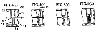
- These tapping bosses have a hatched portion A each, accounting for about a half (180 deg.) of the end face of each cylindrical boss, as protruding from the rest of the boss end in contact with a corresponding tapping boss of the upper casing.
- the area of the protruding portion may be suitably chosen depending on the diameters of the mating bosses.
- the protrusion A faces the direction toward a drive shaft insertion hole as indicated in FIG. 1.
- portions A with a height of 0.1 to 0.15 mm gave good tapping strength and imparted favorable shape quality to the housing.
- the height may be suitably chosen depending on the dimensions of cartridges.
- FIG. 6 illustrates another embodiment of the invention. While the first embodiment used an upper casing 10 with tapping bosses 11 having a protrusion each, this embodiment has a similar construction in a lower casing 20 instead.
- tapping bosses are formed at two points 21a in the frontal part of lower casing 20, at two points 21b in the rear part, and at one point 21c in the frontal, central part. Hatched portions A of the tapping bosses are protrusions from the ends of the bosses that mate with the bosses of the lower casing. Each protrusion A is directed toward a drive shaft insertion hole. In general the direction is toward the mechanically weak region of the upper or lower casing. In the illustrated embodiment the ends of tapping bosses of upper casing 20 is flat as usual.
- protrusions A at the ends of tapping bosses in the first and second embodiments are shaped like steps as in FIG. 5, they may be sloped instead.
- the present invention provides a cartridge of high dimensional accuracy with little possibility of deformation, achieving an effect of producing a tight joint with no gap in the sidewalls of the upper and lower casings of the cartridge housing.
Landscapes
- Casings For Electric Apparatus (AREA)
- Packaging Of Annular Or Rod-Shaped Articles, Wearing Apparel, Cassettes, Or The Like (AREA)
- Packaging For Recording Disks (AREA)
Abstract
Description
Claims (3)
- A cartridge including a housing which holds a tape medium or disk medium therein, said housing being composed of upper and lower casings which are joined with screws in bosses formed at the four corners thereof, characterized in that the bosses in at least one of the upper and lower casings have ends with partially different heights each so that, when the upper and lower casings are joined, the bosses thereof come in contact with one another before the sidewalls of the casings are mated.
- The cartridge of claim 1, wherein the bosses are bosses for tapping and the portions of the ends thereof directed to mechanically weak regions of the housing are protruded.
- The cartridge of claim 2, wherein the bosses have end portions protruded in the direction toward the center of the housing.
Applications Claiming Priority (2)
| Application Number | Priority Date | Filing Date | Title |
|---|---|---|---|
| JP13143299 | 1999-05-12 | ||
| JP13143299A JP3538568B2 (en) | 1999-05-12 | 1999-05-12 | cartridge |
Publications (3)
| Publication Number | Publication Date |
|---|---|
| EP1052640A2 true EP1052640A2 (en) | 2000-11-15 |
| EP1052640A3 EP1052640A3 (en) | 2004-01-14 |
| EP1052640B1 EP1052640B1 (en) | 2006-08-30 |
Family
ID=15057834
Family Applications (1)
| Application Number | Title | Priority Date | Filing Date |
|---|---|---|---|
| EP00108982A Expired - Lifetime EP1052640B1 (en) | 1999-05-12 | 2000-04-27 | Cartridge |
Country Status (4)
| Country | Link |
|---|---|
| US (1) | US6385010B1 (en) |
| EP (1) | EP1052640B1 (en) |
| JP (1) | JP3538568B2 (en) |
| DE (1) | DE60030353T2 (en) |
Families Citing this family (1)
| Publication number | Priority date | Publication date | Assignee | Title |
|---|---|---|---|---|
| JP2009145790A (en) * | 2007-12-18 | 2009-07-02 | Sanyo Electric Co Ltd | Exterior structure and method of constitution the same |
Family Cites Families (15)
| Publication number | Priority date | Publication date | Assignee | Title |
|---|---|---|---|---|
| JPS5633031Y2 (en) * | 1977-10-14 | 1981-08-05 | ||
| JPS5616886U (en) * | 1979-07-17 | 1981-02-14 | ||
| JPS5914954Y2 (en) * | 1979-11-15 | 1984-05-02 | 日立マクセル株式会社 | magnetic tape cartridge |
| JPS6215906Y2 (en) * | 1980-07-28 | 1987-04-22 | ||
| JPS612805Y2 (en) * | 1980-08-04 | 1986-01-29 | ||
| JPS612805A (en) | 1984-06-15 | 1986-01-08 | 株式会社 三協総業 | Tail lock |
| JPH01133275A (en) * | 1988-07-20 | 1989-05-25 | Hitachi Maxell Ltd | Magnetic tape cartridge |
| JPH02123772A (en) | 1988-11-02 | 1990-05-11 | Fujikura Ltd | Automatic regulator for acceptance angle of solar cell |
| JP3239393B2 (en) * | 1991-10-21 | 2001-12-17 | ソニー株式会社 | Tape cassette |
| EP0568060A3 (en) * | 1992-05-01 | 1994-12-21 | Minnesota Mining & Mfg | Cassette screw bosses with ribbed surfaces. |
| JPH06243635A (en) * | 1993-02-18 | 1994-09-02 | Sony Corp | Tape cassette |
| US5730382A (en) * | 1995-01-24 | 1998-03-24 | Tdk Corporation | Tapping bosses of magnetic tape cassette |
| JPH08306158A (en) * | 1995-04-13 | 1996-11-22 | Fuji Photo Film Co Ltd | Tape cassette |
| JP3169121B2 (en) * | 1996-11-11 | 2001-05-21 | ティーディーケイ株式会社 | Tape cassette |
| JP3479448B2 (en) * | 1998-01-23 | 2003-12-15 | Tdk株式会社 | Tape cassette |
-
1999
- 1999-05-12 JP JP13143299A patent/JP3538568B2/en not_active Expired - Fee Related
-
2000
- 2000-04-27 EP EP00108982A patent/EP1052640B1/en not_active Expired - Lifetime
- 2000-04-27 DE DE60030353T patent/DE60030353T2/en not_active Expired - Fee Related
- 2000-05-08 US US09/566,021 patent/US6385010B1/en not_active Expired - Fee Related
Also Published As
| Publication number | Publication date |
|---|---|
| EP1052640A3 (en) | 2004-01-14 |
| DE60030353D1 (en) | 2006-10-12 |
| US6385010B1 (en) | 2002-05-07 |
| JP2000322861A (en) | 2000-11-24 |
| DE60030353T2 (en) | 2007-08-30 |
| EP1052640B1 (en) | 2006-08-30 |
| JP3538568B2 (en) | 2004-06-14 |
Similar Documents
| Publication | Publication Date | Title |
|---|---|---|
| JP3451946B2 (en) | connector | |
| JP2503322B2 (en) | Waterproof connector | |
| EP0488087A2 (en) | A connector | |
| JP3337008B2 (en) | connector | |
| US6385010B1 (en) | Cartridge | |
| JP4045206B2 (en) | Connector support structure | |
| JP3468902B2 (en) | Magnetic disk cartridge and method of manufacturing the same | |
| JPH0516711Y2 (en) | ||
| JP2580711Y2 (en) | Connector housing | |
| US7527163B2 (en) | Top cover fixing structure | |
| US6132235A (en) | Connector lock mechanism | |
| JP3522460B2 (en) | Tunnel wall segment | |
| JPH0966989A (en) | Board material-containing box | |
| US20010040309A1 (en) | Method of forming air vent holes of a rear case for an lcd monitor, and an apparatus therefor | |
| JP3701483B2 (en) | Lens fixing structure to the lamp case | |
| US7044766B2 (en) | Automotive electrical connection box and method of assembling thereof | |
| JPH07249878A (en) | Decorative body fixing device for electronic apparatus | |
| JP2002170623A (en) | Electric connector | |
| JP3087658B2 (en) | connector | |
| JPH05166332A (en) | Tape cassette | |
| JPH04249139A (en) | chassis boss seat | |
| JPH0510300Y2 (en) | ||
| JP3456017B2 (en) | Disk cassette shell and mold device for molding the shell | |
| JPH0355900A (en) | Housing for electronic device | |
| JP3052836B2 (en) | connector |
Legal Events
| Date | Code | Title | Description |
|---|---|---|---|
| PUAI | Public reference made under article 153(3) epc to a published international application that has entered the european phase |
Free format text: ORIGINAL CODE: 0009012 |
|
| AK | Designated contracting states |
Kind code of ref document: A2 Designated state(s): AT BE CH CY DE DK ES FI FR GB GR IE IT LI LU MC NL PT SE |
|
| AX | Request for extension of the european patent |
Free format text: AL;LT;LV;MK;RO;SI |
|
| PUAL | Search report despatched |
Free format text: ORIGINAL CODE: 0009013 |
|
| AK | Designated contracting states |
Kind code of ref document: A3 Designated state(s): AT BE CH CY DE DK ES FI FR GB GR IE IT LI LU MC NL PT SE |
|
| AX | Request for extension of the european patent |
Extension state: AL LT LV MK RO SI |
|
| 17P | Request for examination filed |
Effective date: 20040318 |
|
| AKX | Designation fees paid |
Designated state(s): DE GB |
|
| GRAP | Despatch of communication of intention to grant a patent |
Free format text: ORIGINAL CODE: EPIDOSNIGR1 |
|
| GRAS | Grant fee paid |
Free format text: ORIGINAL CODE: EPIDOSNIGR3 |
|
| GRAA | (expected) grant |
Free format text: ORIGINAL CODE: 0009210 |
|
| AK | Designated contracting states |
Kind code of ref document: B1 Designated state(s): DE GB |
|
| REG | Reference to a national code |
Ref country code: GB Ref legal event code: FG4D |
|
| REF | Corresponds to: |
Ref document number: 60030353 Country of ref document: DE Date of ref document: 20061012 Kind code of ref document: P |
|
| PGFP | Annual fee paid to national office [announced via postgrant information from national office to epo] |
Ref country code: DE Payment date: 20070426 Year of fee payment: 8 |
|
| PLBE | No opposition filed within time limit |
Free format text: ORIGINAL CODE: 0009261 |
|
| STAA | Information on the status of an ep patent application or granted ep patent |
Free format text: STATUS: NO OPPOSITION FILED WITHIN TIME LIMIT |
|
| 26N | No opposition filed |
Effective date: 20070531 |
|
| PGFP | Annual fee paid to national office [announced via postgrant information from national office to epo] |
Ref country code: GB Payment date: 20070420 Year of fee payment: 8 |
|
| GBPC | Gb: european patent ceased through non-payment of renewal fee |
Effective date: 20080427 |
|
| PG25 | Lapsed in a contracting state [announced via postgrant information from national office to epo] |
Ref country code: DE Free format text: LAPSE BECAUSE OF NON-PAYMENT OF DUE FEES Effective date: 20081101 |
|
| PG25 | Lapsed in a contracting state [announced via postgrant information from national office to epo] |
Ref country code: GB Free format text: LAPSE BECAUSE OF NON-PAYMENT OF DUE FEES Effective date: 20080427 |