EP1052599A2 - Formation of orthogonally projected image from centrally projected image - Google Patents
Formation of orthogonally projected image from centrally projected image Download PDFInfo
- Publication number
- EP1052599A2 EP1052599A2 EP00201632A EP00201632A EP1052599A2 EP 1052599 A2 EP1052599 A2 EP 1052599A2 EP 00201632 A EP00201632 A EP 00201632A EP 00201632 A EP00201632 A EP 00201632A EP 1052599 A2 EP1052599 A2 EP 1052599A2
- Authority
- EP
- European Patent Office
- Prior art keywords
- photographing
- image
- projected image
- orthogonally projected
- section
- Prior art date
- Legal status (The legal status is an assumption and is not a legal conclusion. Google has not performed a legal analysis and makes no representation as to the accuracy of the status listed.)
- Withdrawn
Links
Images







Classifications
-
- G—PHYSICS
- G06—COMPUTING OR CALCULATING; COUNTING
- G06T—IMAGE DATA PROCESSING OR GENERATION, IN GENERAL
- G06T5/00—Image enhancement or restoration
- G06T5/80—Geometric correction
Definitions
- the present invention relates to an image formation system, more particularly to an image formation system which prepares an orthogonally projected image from a centrally projected image such as photographs, and prepares and amends an image map so as to be able to understand field conditions by dimensioning a map on the image and superposing images on the map.
- image formation system shall contain a wide concept such as "acquire digital image,” “detect digital image” and “take a picture.”
- drawings obtained by surveying in a field have been prepared by paper, a pencil and the like typified by a plane table survey.
- line drawings of the fields have been prepared by a combination of a survey instrument and a portable computer typified by a digital plane table.
- a digital plane table in order to acquire an image necessary for performing an orthogonally projected image preparation and three-dimensional data such as a control point, a rough plan for surveying and photographing a pertinent region was made, or alternatively works such as the survey and the photographing were conducted in the field without making any plan.
- the object of the present invention is to remove the failures of the survey and the insufficiency of the data in the survey and photographing field in preparing and amending the orthogonally projected image.
- Another object of the present invention is to remove the time for re-photographing and re-surveying in the field.
- Still another object of the present invention is to provide an image formation system, which is capable of simulating a photographing plan based on a necessary precision and an orthogonally projected image preparation range so as to keep a conformity of a work on a desk to the actual work in the field, and is capable of selecting the optimal equipment, thus supporting the survey and photographing free from errors in the field.
- the object of the present invention is to provide an image formation system, wherein the photographing conditions such as a photographing range, a photographing position, equipment to be used, and the number of photographs, which have been objects of surveys and photographing plan on a desk, are calculated and selected, acquirement of the image and the survey are made to be possible while actually giving instructions about them and confirming them in the field, thus enabling an effective orthogonally projected image preparation without failures, mistakes and re-photographing and re-surveying.
- the photographing conditions such as a photographing range, a photographing position, equipment to be used, and the number of photographs, which have been objects of surveys and photographing plan on a desk
- the object of the present invention is to provide an image formation system in which anybody can simultaneously perform a simple survey and acquirement of the orthogonally projected image by using GPS.
- Still another object of the present invention is to provide an image formation system which is capable of preparing sequentially a detail drawing of the orthogonally projected image by accumulating survey data and image data, and preparing the orthogonally projected image with a desired scale.
- an image formation system which comprises:
- Fig. 1 is a total constitution of the image formation system of the present invention.
- the image formation system comprises an image formation apparatus 2000, a field image processing apparatus 1000 and a GPS receiver 3000.
- the image formation apparatus 2000 forms mainly an orthogonally projected image.
- the field image processing apparatus 1000 performs amendments, preparations and confirmations of the orthogonally projected image in a field.
- the GPS receiver 3000 confirms a present position and spots to be amended.
- the image formation apparatus 2000 and the field image processing apparatus 1000 are built separately in the image formation system here, these apparatuses may be united into one.
- the GPS receiver 3000 may be included in the unit composed of these apparatuses.
- FIG. 2 A schematic flowchart for preparing the orthogonally projected image is shown in Fig. 2. Note that the preparation of the orthogonally projected image and the amendment thereof are executed based on a map in accordance with the same processing except that only a material used for a preparation or an amendment differs.
- a map of a region for which the orthogonally projected image is prepared a digital map is obtained (S500).
- the map data concerning the map is read by a scanner or the like, and a digital map obtaining by vectorizing it may be used. Or, the digital map may be merely used as a reference.
- the image formation apparatus 2000 performs the preparation (S500).
- the image for preparing the orthogonally projected image includes an image photographed from an airplane or a platform (such as a kite-balloon, a radio-controlled model helicopter and a crane truck), a satellite image and the like. Or, such images available on the market may be used.
- spots to be desired to be made in the form of images, spots that were not made in the form of images in the previous preparation processing, and areas that are desired to be investigated and additionally surveyed are checked, and an orthogonally image acquiring plan is made (3600).
- the surveyor travels to a location where the preparation of the orthogonally projected image is desired or where images were not made in the previous investigation or the investigated result are to be amended while navigating by the GPS and the like, and performs the survey and the photographing at the field (S700).
- a final orthogonally image is obtained by integrating investigation data and image that are obtained in the field, images that have been prepared and obtained, and control point data if this exists (S800).
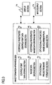
- the constitution of the image formation apparatus 2000 is shown in Fig. 3.
- the image formation apparatus 2000 comprises a control point data storing section 50, an image data storing section 60, an additionally investigated control point data storing section 55, an additionally investigated image data storing section 65, an orthogonally projected image formation section 70 and an orthogonally projected image acquirement plan making section 80.
- the image formation apparatus 2000 has a display section 72 and an input/output section 74 either outside or inside thereof.
- Such means (function) can be realized by, for example, a personal computer (PC) and the like.
- the control point data storing section 50 is a portion for storing the control point data required for preparing the first orthogonally projected image.
- the image data storing section 60 is a portion for storing a digitized photographed image from which the orthogonally projected image is prepared.
- the additionally investigated control point data storing section 55 is a portion for storing the control point survey data which is additionally investigated in the field.
- the additionally investigated image data storing section 65 is a portion for storing digital image data which is additionally investigated and photographed in the field.
- the orthogonally projected image formation section 70 is a portion which integrates the control point data and the image data and thus prepares and synthesizes the final orthogonally projected image.
- the orthogonally projected image acquirement plan making section 80 is a portion for making an orthogonally projected image acquirement plan for spots to be amended.
- the display section 72 performs a two-dimensional displaying or a three-dimensional displaying like a CRT, a liquid crystal display and a plasma display.
- the display section 72 displays the orthogonally projected image formed by the orthogonally projected image formation section 70 and various kinds of data.
- the input/output section 74 inputs/outputs various kinds of image data and three-dimensional coordinate data of a survey instrument.
- various kinds of input devices and output devices such as an optical disc apparatus, a recording medium taking a card type (HDD, a memory), a floppy disc, a key board, a pen, a mouse, a CD-ROM disc drive can be provided.
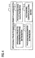
- Fig. 4 shows a constitution of the orthogonally projected image acquirement plan making section 80.
- the orthogonally projected image acquirement plan making section 80 comprises an orthogonally projected image preparation range setting section 82, a photographing information setting section 85, a photographable range calculating section 87 and a photographing condition calculation section 89.
- Such means (function) can be realized by, for example, a personal computer (PC) and the like.
- the orthogonally projected image preparation range setting section 82 sets an orthogonally projected image preparation range in which the preparation of the orthogonally projected image is desired.
- the photographing information setting section 85 sets photographing camera information for photographing an image from which the orthogonal projected image is prepared.
- the photographing camera information is information of a camera to be used and various kinds of photographing information.
- the photographing camera information is at least one of an angular field of the photographing lens, a size of the photographing plane, a focal length of the photographing lens, a photographing position in which the orthogonally projected image preparation range and the position are related to each other, a pixel size of the CCD, and a reading precision of the film plane.
- information setting section 85 information such as information on a camera for photographing a still picture or a camera for photographing a moving picture, information of a ground photographing and an aerial photographing, and information of a required precision can be set.
- the photographable range calculating section 87 calculates the orthogonally projected range which can be photographed and the like, based on the set information such as the photographing camera information.
- the photographing condition calculating section 89 calculates the photographing conditions for obtaining the photographed image from which the orthogonally projected image can be appropriately formed in the orthogonally projected image preparation range, based on the photographable range.
- the photographing condition is at least one of the number of times of the photographings, a photographing direction, a photographing angle, and a photographing position.
- the photographing condition is at least one of the photographing direction, the photographing angle, a movement direction, a movement speed and a photographing position.
- the photographing condition calculating section 89 calculates the photographing conditions including a flight attitude.
- the photographing condition calculating section 89 calculates the photographing conditions including a photographing angle and an angular field.
- the constitution of the field image processing apparatus 1000 is shown in Fig. 5.
- the field image processing apparatus 1000 comprises a data storing section 1 for storing various kinds of data, an orthogonally projected image formation section 2 and a navigation section 8.
- the field image processing apparatus 1000 has a display section 6 and an input/output section 7 inside or outside thereof.
- Such means can be realized by, for example, a portable personal computer (PC).
- the data storing section 1 previously stores three-dimensional data and image data measured by an survey instrument or the like and map data.
- the orthogonally projected image formation section 2 is the same as the orthogonally projected image formation section 70 in the image formation apparatus 2000.
- the navigation section 8 has a GPS data receiving section 16 and a navigation image display section 17.
- the navigation section 8 allows the navigation image display section 17 to display information relating to the present position received from the GPS by the GPS data receiving section 16, and the navigation section 8 is used by the surveyor for knowing the present position where the surveyor currently exists and moving to a place where the orthogonally projected image is prepared, additionally investigated, and amended.
- the navigation section can confirm the orthogonally projected image amended by the navigation image display section 17. Note that the navigation image display section 17 may serve as the display section 6.
- the display section 6 performs a two-dimensional displaying or a three-dimensional displaying such as a CRT, a liquid crystal display or a plasma display.
- the display section 6 displays the orthogonal projected image formed by the orthogonal projected image formation section 2 and data stored in the data storing section 1.
- the input/output section 7 inputs/outputs various kinds of data and three-dimensional coordinate data from a three-dimensional coordinate input apparatus of the survey instrument or the like from/to other apparatuses.
- various kinds of input devices and output devices such as an optical disc device, a recording medium taking a card type (HDD, a memory), a floppy disc, a key board, a pen, a mouse, a CD-ROM disc drive can be provided.
- the display section 6 and the input/output section 7 of the field image processing section 1000 can be used as the display section 72 and the input/output section 74 of the image formation apparatus 2000.
- the display section 72 and the input/output section 74 of the image formation apparatus 2000 can be used as the display section 6 and the input/output section 7 of the field image processing section 1000.
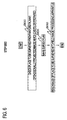
- FIG. 6 A flowchart concerning the orthogonally projected image preparation processing, the checking processing of spots to be amended, and the processing for making a survey plan is shown in Fig. 6.
- the checking processing of spots to be amended, and the processing for making a survey plan step S600
- places for which it is intended to prepare the orthogonally projected image and places having less data or for which further survey has to be performed are confirmed (step S610).
- a survey plan is made by the orthogonally projected image acquirement plan making section 80 in the image formation apparatus 2000, in preparing the orthogonally projected image and amending it (step S620).
- FIG. 7 A flowchart concerning the survey plan making is shown in Fig. 7.
- the survey plan making in the step S 620 by the orthogonally projected image acquirement plan making section 80 is further described in detail.
- regions to be prepared or amended based on the map or the image which was prepared or obtained in the step S500 are specified by the input/output section 74 having the input/output device such as a pen and a mouse (S625).
- the specified data is set in the orthogonally projected image preparation range setting section 82.
- the orthogonally projected image exists, the orthogonally projected image is displayed, and then the region is specified. In the case of the digital map, these are read out.
- the region displayed on the display screen about the map is specified.
- the numerical data as to this map may be entered.
- a scale of the image to be acquired is adjusted, and the screen is made to stand by the orthogonally projected image display.
- an image is not displayed.
- the same size as that of an area to be specified may be specified by an input device such as a cursor and a pen.
- an area of the region is calculated (step S630).
- Photographing conditions that are various kinds of parameters necessary for photographing by a camera to be used are calculated by the photographing condition calculating section 89, and the photographing range at the time of photographing one sheet of photograph is calculated by the photographable range calculating section 87 (step S640). Setting of various kinds of information such as the photographing conditions necessary for the photographing is set in the photographing information setting section 85. Detailed procedures of the calculation processing at the time of photographing one sheet of photograph will be described later.
- a summary overlapping rate is set based on the photographing range calculated for one sheet of photograph (step S660).
- the overlapping rate is ordinarily 10 %, and, in the case of a stereo photographing, the overlapping rate can be set to 60 %.
- the photographing position and the number of sheets of photographs are calculated (step S665). Since an aerial photographing from a platform is ordinarily vertical photographing, the photographing position is a center of the photographing range for one sheet of photograph. On the other hand, in the case of land photographing, the photographing position is calculated by relations of a photographing angle, an angular field, a photographing distance and a photographing range.
- the photographing position and the number of sheets of photographs are displayed on the orthogonally projected image (step S665).
- a most suitable camera is selected, and the survey and the photographing in the field can be performed depending on the photographing conditions such as the photographing position and the number of sheets of photographs.
- Fig. 8 is an explanatory view concerning a photographing position of the orthogonally projected image.
- the orthogonally projected image including a place to be surveyed, a digital map and various kinds of photographing conditions are respectively transferred to the data storing section 1 of the field image processing apparatus 1000 constituted by, for example, a portable computer, and read thereinto (step S680). If these are constituted on the same apparatus, the transfer and the reading need not to be performed. Since the survey plan has been made as described above, the step proceeds to a processing of a survey, a photographing, an additional survey and an amendment in the field.
- a flowchart for calculating the photographing range for one sheet of photograph is shown in Fig. 9.
- a necessary survey precision or a scale is first set (step S642). Here, it is determined with at least what precision, for example, on the order of several centimeter or several tens centimeter, the survey is conducted, or it is determined what image scale is desired. The determined precision and the determined image scale are set.
- the photographing camera information of a usable camera such as an angular field of a lens, a size of a photographing plane, and a focal length is set to the photographing information setting section 85 (step S644).
- a plurality of photographing camera information are set.
- the angular field ⁇ i is obtained by the following formula. Accordingly, the size d of the photographing plane instead of the angular field may be entered.
- ⁇ i 2 tan -1 ( (d/2) / f) where ⁇ i is the angular field, d is a size of the photographing plane and f is a focal length.
- step S646 it is decided whether the photographing is an aerial photographing or a land photographing, and the subsequent procedure is parted.
- the flight altitude is a problem. Since the flight altitude differs depending on the photographing platform such as a kite-balloon, a radio-controlled model helicopter and a crane truck, the photographing platform to be used is set (step S648). When a plurality of platforms are possessed, the plurality of platforms may be set. Then, the flight altitude H is calculated by the following formula (step S650). Note that ⁇ s in the following formula is a value set previously in the step S642 as a required precision. In the case of a scale, ⁇ s is converted to a proper value and set.
- ⁇ p is a pixel size.
- ⁇ p is a reading-out precision of a scanner.
- H ( ⁇ s ⁇ f)/ ⁇ p where H is a flight altitude, ⁇ s is a required precision and ⁇ p is a pixel size of a CCD or a reading-out precision of a film plane.
- the photographable range calculating section 87 calculates the photographing range R equivalent to one sheet of photograph by the following formula.
- the number of calculations corresponding to the number of cameras and lenses are performed.
- R H ⁇ tan( ⁇ i) where ⁇ i is an angular field.
- a step proceeds to a processing of setting the overlapping rate (step S660).
- a proper platform can be selected based on one of the photographing camera information such as the angular field ⁇ i of the lens, the required precision ⁇ s, the calculated flight altitude H and the photographing range R.
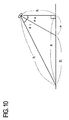
- FIG. 10 An explanatory view concerning the relationship between the photographing range and the angle is shown in Fig. 10.
- the photographing is performed using a camera with an angular field ⁇ i when the photographing height and the photographing angle are h and ⁇ a, respectively.
- the photographing height h is decided to some extent.
- this photographing height h is set to the photographing information setting section 85, and the photographing angle ⁇ a is also set if it is decided (step S652).
- the photographing condition calculating section 89 decides the angular field by the lens and the photographing angle is decided by the following formula (step S654).
- the photographable range calculating section 87 determines the photographing range R by the following formula (step S656).
- a lens having the widest range is selected based on a focal length of a manual photograph and an angular field.
- R h(tan( ⁇ i+ ⁇ a) - tan ⁇ a)
- step S700 the survey processing and the photographing processing in the field are described in detail.
- FIG. 11 A flowchart concerning the survey processing and the photographing processing in the field is shown in Fig. 11.
- the surveyor goes to the field to be surveyed, and a survey range and the survey position are displayed on the field image processing apparatus 1000 constituted by a portable computer and the like (step S710).
- the field image processing apparatus 1000 constituted by a portable computer and the like.
- the survey range and the survey position are displayed on the orthogonally projected image.
- the digital map exist the survey range and the survey position are superposed on the maps, and then displayed on the display screen.
- the orthogonally projected image and the maps do not exist, only the photographing range and the photographing position are displayed. Note that coordinate system of these displays and scales are set to desired values.
- the field image processing apparatus 1000 allows the present position to be displayed thereon in cooperation with the GPS (step S720).
- the surveyor confirms a range to be surveyed while watching the display, and the surveyor surveys points necessary for preparing the orthogonally projected image in the photographing range, spots to be surveyed in detail and positions to be additionally surveyed using a survey instrument such as a GPS and a total station (step S730). If six or more survey spots first exist in one photographing range, no survey should be performed. However, when they do not exist, when the detail survey is further required, or when amendments are desired, the surveys of the spots are previously performed.
- the surveyor goes to an accurate photographing position while watching the display of the photographing position and the present position by the GPS, and photographs an image of the place by a digital camera or the like, under conditions of a predetermined focal length and an angular field in a predetermined photographing direction obtained by the orthogonally projected image acquirement plan making section 80 (step S740).
- the photographing is performed by a camera mounted on a car
- the display section 6 on the portable computer or the navigation image display section 17 is observed while navigating by the GPS, and the photographing is performed at the photographing position.
- the video camera runs in the photographing position at an obtained movement speed, thus obtaining an image by the photographing using the video camera.
- an aerial photographing is necessary the photographing is performed while adjusting the image and the photographing position using various kinds of platforms such as a balloon and a helicopter.
- the photographed image is read into the field image processing apparatus 1000 (step S750).
- the orthogonally projected image preparation processing and the amendment processing are performed (step S760).
- the orthogonally projected image preparation processing and the amendment processing can be performed using the orthogonally projected image formation section 70 of the image formation section 2000 or the orthogonally projected image formation section 2 of the field image processing section 1000. If a satisfactory orthogonally projected image cannot be obtained in this step, the processing of the step S700 should be repeated until a satisfactory orthogonally projected image can be obtained.
- the photographing range and the photographing position are displayed based on the prepared orthogonally projected image in this step. If the need arises, the step S700 can be repeated. Detailed procedures for preparing the orthogonally projected image will be described later.
- the various kinds of information such as the photographing camera information has been set in the photographing information setting section 85
- the various kinds of information can also be set to a proper recording apparatus such as the data storing section 1 of the field image processing apparatus 1000, and stored therein.
- step S800 an orthogonally projected image integration preparation processing
- FIG. 12 A flowchart concerning the orthogonally projected image integration preparation processing is shown in Fig. 12.
- the processing in this step is executed by reading image data and data surveyed in the field into the image formation apparatus 2000 (step S810).
- the below description is done for the case where the orthogonally projected image is previously acquired or obtained.
- the following processing can be executed by considering that corresponding data does not exist.
- the control point data surveyed in the field is inputted to the additional survey control point data storing section 55, and the image data is inputted to the additional survey image data storing section 65.
- the image data of the first orthogonally projected image is inputted to the image data storing section 60, and its control point data is inputted to the control point data storing section 50.
- the control point data surveyed in the field is inputted to the control point data storing section 50, and the image data is inputted to the image data storing section 60.
- control point data stored in the control point data storing section 50 and the additional survey control point data storing section 55 can be stored in a state where they are mixed, and both of them are used. Then, when a scale of the orthogonally projected image to be prepared is determined (step S820), a preparation of the orthogonally projected image is performed by an orthogonally projected image formation processing as described later (step S830). Note that the orthogonally projected image integration preparation processing (step S800) can be performed by the field orthogonally projected image preparation system 1000 not by the digital image formation apparatus 2000.
- FIG. 13 A flowchart of the orthogonally projected image preparation processing is shown in Fig. 13.
- the photographed image is read (step S201).
- the image coordinates of the six or more photographed control points photographed onto the photographed image are measured (step S203).
- the photographed control points photographed are obtained by previously surveying the land coordinates by a survey instrument.
- the image coordinates and the land coordinates are made to correspond to each other, and coordinate conversion parameters are obtained (step S205). This is performed by the three dimensional projective transformation formula shown below.
- step S207 the land coordinates of each pixel on the orthogonally projected image are calculated.
- the image coordinates (x, y) of the orthogonally projected image are transformed to the land coordinates (X, Y, Z).
- the land coordinates (X, Y, Z) are calculated using the transformation parameters previously obtained in the step S205 for the coordinate transformation parameter calculation processing.
- the land coordinates (X, Y, Z) corresponding to the image coordinates (x, y) of the orthogonally projected image are given by the following formula. In such manner, the acquirement position of each pixel on the orthogonally projected image can be obtained.
- the image coordinates (x, y) corresponding to the land coordinates (X, Y, Z) obtained by the Formula 1 in the step S207 are calculated (S209). Based on the image coordinates (x, y) obtained in such manner, a value of density on the land coordinates (X, Y, Z) of the pertinent image is acquired. This value of density is a density of a pixel in the two dimensional position (X, Y) on the orthogonally projected image. In the above described manner, an image density to be adhered to the position (X, Y) on the land coordinates is acquired. By performing the above described processings for all pixels of the orthogonally projected image, an image adhesion is performed (step S211).
- the image adhesion is performed while transforming the selected image to a resolution corresponding to a desired scale.
- the image adhesion concerning the image density was described, the present invention is not limited to this.
- the image adhesion can be performed by acquiring proper information such as colors and patterns.
Landscapes
- Physics & Mathematics (AREA)
- General Physics & Mathematics (AREA)
- Engineering & Computer Science (AREA)
- Theoretical Computer Science (AREA)
- Image Processing (AREA)
- Processing Or Creating Images (AREA)
Abstract
Description
- (X0, Y0)
- : a position in the upper left of the orthogonally projected image in the land coordinate system
- (ΔX, ΔY)
- : a size of one pixel in the land coordinate system (example: m/pixel)
- (x, y)
- : image coordinates of the orthogonally projected image
- (X, Y, Z)
- : land coordinates (three dimensional coordinates)
- a, b, c, d
- : coefficients of a plane equation formed by a plurality of control points which interpolate certain image coordinates (x, y)
Claims (8)
- An image formation system comprising:a range setting section for setting a first range in which an orthogonally projected image is to be formed;an information setting section for setting photographing camera information relating to a camera which photographs an image from which the orthogonally projected image is to be formed;a range calculating section for obtaining a second range which can be photographed, based on the photographing camera information set to said information setting section; anda condition calculating section for calculating photographing conditions to obtain a photograph image which can properly form the orthogonally projected image, in the first range set to said range setting section, based on the second range obtained by said range calculating section.
- The image formation system according to claim 1,said image formation system further comprisingan orthogonally projected image formation section for forming the orthogonally projected image from the photograph image photographed by the camera,
wherein said range setting section further sets a third range in which a new orthogonally projected image is to be formed based on a new image, in the orthogonally projected image formed by said orthogonally projected image formation section,said range calculating section obtains a fourth range which can be newly photographed, based on the photographing camera information set to said information setting section, andsaid condition calculating section calculates the photographing conditions to obtain the photograph image from which the orthogonally projected image can be properly formed, in the third range set to said range setting section, based on the fourth range obtained by said range calculating section. - The image formation system according to claim 1,said image formation system further comprisinga navigation section including a GPS,
wherein position information is displayed. - The image formation system according to claim 1, wherein said camera is a camera for photographing a still picture, and the photographing conditions calculated by said condition calculating section is at least one of the number of times of photographings, a photographing direction, a photographing angle and a photographing position.
- The image formation system according to claim 1, wherein said camera is a camera for photographing a moving picture, and the photographing conditions calculated by said condition calculating section is at least one of a photographing direction, a photographing angle, a movement direction, a movement speed and a photographing position.
- The image formation system according to claim 1, wherein said condition calculating section calculates photographing conditions including a flight altitude in the case of an aerial photographing, or calculates photographing conditions including a photographing angle and an angular field in the case of a land photographing.
- The image formation system according to claim 1, wherein the photographing camera information set to said information setting section is at least one of an angular field of a photograph lens, a size of a photograph plane, a focal length of the photograph lens and a photograph position related to the first range.
- The image formation system according to claim 1, wherein at least one of information of either the camera for photographing a still picture or the camera for photographing a moving picture, information either the aerial photographing or the land photographing and information of a required precision in set to said information setting section.
Applications Claiming Priority (2)
| Application Number | Priority Date | Filing Date | Title |
|---|---|---|---|
| JP12891099A JP4237868B2 (en) | 1999-05-10 | 1999-05-10 | Image forming system |
| JP12891099 | 1999-05-10 |
Publications (2)
| Publication Number | Publication Date |
|---|---|
| EP1052599A2 true EP1052599A2 (en) | 2000-11-15 |
| EP1052599A3 EP1052599A3 (en) | 2003-02-12 |
Family
ID=14996399
Family Applications (1)
| Application Number | Title | Priority Date | Filing Date |
|---|---|---|---|
| EP00201632A Withdrawn EP1052599A3 (en) | 1999-05-10 | 2000-05-08 | Formation of orthogonally projected image from centrally projected image |
Country Status (3)
| Country | Link |
|---|---|
| US (1) | US7015967B1 (en) |
| EP (1) | EP1052599A3 (en) |
| JP (1) | JP4237868B2 (en) |
Cited By (1)
| Publication number | Priority date | Publication date | Assignee | Title |
|---|---|---|---|---|
| CN106546223A (en) * | 2015-09-18 | 2017-03-29 | 北京林业大学 | A kind of method that use digital camera carries out the design of angle gauge point sampling Optimal Control angle |
Families Citing this family (18)
| Publication number | Priority date | Publication date | Assignee | Title |
|---|---|---|---|---|
| JP2003110981A (en) * | 2001-09-28 | 2003-04-11 | Hiroboo Kk | Aerial video image processing system and wireless small- sized unmanned flying body |
| JP4523833B2 (en) * | 2004-11-18 | 2010-08-11 | 株式会社パスコ | Photography planning support apparatus and program therefor |
| JP4739291B2 (en) * | 2007-08-09 | 2011-08-03 | 富士フイルム株式会社 | Shooting angle of view calculation device |
| JP5097480B2 (en) * | 2007-08-29 | 2012-12-12 | 株式会社トプコン | Image measuring device |
| US8485430B2 (en) | 2011-12-06 | 2013-07-16 | Honeywell International, Inc. | Hand held bar code readers or mobile computers with cloud computing services |
| US9041518B2 (en) | 2012-01-26 | 2015-05-26 | Hand Held Products, Inc. | Portable RFID reading terminal with visual indication of scan trace |
| US8881982B2 (en) | 2012-04-20 | 2014-11-11 | Honeywell Scanning & Mobility | Portable encoded information reading terminal configured to acquire images |
| US9443119B2 (en) | 2012-04-20 | 2016-09-13 | Hand Held Products, Inc. | Portable encoded information reading terminal configured to locate groups of RFID tags |
| US9013275B2 (en) | 2012-04-20 | 2015-04-21 | Hand Held Products, Inc. | Portable encoded information reading terminal configured to adjust transmit power level |
| US8727225B2 (en) | 2012-04-20 | 2014-05-20 | Honeywell International Inc. | System and method for calibration and mapping of real-time location data |
| US9536219B2 (en) | 2012-04-20 | 2017-01-03 | Hand Held Products, Inc. | System and method for calibration and mapping of real-time location data |
| US9558386B2 (en) | 2012-05-15 | 2017-01-31 | Honeywell International, Inc. | Encoded information reading terminal configured to pre-process images |
| US9064254B2 (en) | 2012-05-17 | 2015-06-23 | Honeywell International Inc. | Cloud-based system for reading of decodable indicia |
| US9092683B2 (en) | 2012-07-10 | 2015-07-28 | Honeywell International Inc. | Cloud-based system for processing of decodable indicia |
| US9594939B2 (en) | 2013-09-09 | 2017-03-14 | Hand Held Products, Inc. | Initial point establishment using an image of a portion of an object |
| EP3040904B1 (en) | 2014-12-31 | 2021-04-21 | Hand Held Products, Inc. | Portable rfid reading terminal with visual indication of scan trace |
| JP6275358B1 (en) * | 2017-02-28 | 2018-02-07 | 株式会社オプティム | Distance calculation system, method and program |
| JP6854195B2 (en) | 2017-06-09 | 2021-04-07 | 株式会社トプコン | Image processing device, image processing method and program for image processing |
Family Cites Families (10)
| Publication number | Priority date | Publication date | Assignee | Title |
|---|---|---|---|---|
| US4908642A (en) * | 1987-04-20 | 1990-03-13 | Hiroshi Komatsuzaki | Camera |
| US5247356A (en) * | 1992-02-14 | 1993-09-21 | Ciampa John A | Method and apparatus for mapping and measuring land |
| FR2696843B1 (en) | 1992-10-14 | 1994-12-09 | Matra Sep Imagerie Inf | High resolution remote camera for aerial carrier. |
| US5517419A (en) | 1993-07-22 | 1996-05-14 | Synectics Corporation | Advanced terrain mapping system |
| US5604534A (en) * | 1995-05-24 | 1997-02-18 | Omni Solutions International, Ltd. | Direct digital airborne panoramic camera system and method |
| US5878356A (en) | 1995-06-14 | 1999-03-02 | Agrometrics, Inc. | Aircraft based infrared mapping system for earth based resources |
| WO1998026252A2 (en) | 1996-12-11 | 1998-06-18 | Interval Research Corporation | Moving imager camera for track and range capture |
| JP3990002B2 (en) * | 1997-05-22 | 2007-10-10 | 株式会社トプコン | Image measuring device |
| DE69829091T2 (en) * | 1997-05-22 | 2006-02-09 | Kabushiki Kaisha Topcon | measuring device |
| US6442293B1 (en) * | 1998-06-11 | 2002-08-27 | Kabushiki Kaisha Topcon | Image forming apparatus, image forming method and computer-readable storage medium having an image forming program |
-
1999
- 1999-05-10 JP JP12891099A patent/JP4237868B2/en not_active Expired - Fee Related
-
2000
- 2000-05-05 US US09/564,990 patent/US7015967B1/en not_active Expired - Fee Related
- 2000-05-08 EP EP00201632A patent/EP1052599A3/en not_active Withdrawn
Cited By (1)
| Publication number | Priority date | Publication date | Assignee | Title |
|---|---|---|---|---|
| CN106546223A (en) * | 2015-09-18 | 2017-03-29 | 北京林业大学 | A kind of method that use digital camera carries out the design of angle gauge point sampling Optimal Control angle |
Also Published As
| Publication number | Publication date |
|---|---|
| EP1052599A3 (en) | 2003-02-12 |
| US7015967B1 (en) | 2006-03-21 |
| JP2000321059A (en) | 2000-11-24 |
| JP4237868B2 (en) | 2009-03-11 |
Similar Documents
| Publication | Publication Date | Title |
|---|---|---|
| EP1052599A2 (en) | Formation of orthogonally projected image from centrally projected image | |
| AU2008322565B2 (en) | Method and apparatus of taking aerial surveys | |
| US5596494A (en) | Method and apparatus for acquiring digital maps | |
| US7415356B1 (en) | Techniques for accurately synchronizing portions of an aerial image with composited visual information | |
| CA2821602C (en) | Oblique geolocation and measurement system | |
| KR101285360B1 (en) | Point of interest displaying apparatus and method for using augmented reality | |
| US6930715B1 (en) | Method, system and program product for augmenting an image of a scene with information about the scene | |
| US7187401B2 (en) | System and a method of three-dimensional modeling and restitution of an object | |
| US5774826A (en) | Optimization of survey coordinate transformations | |
| US20030160757A1 (en) | Surveying system | |
| EP1965170A1 (en) | Surveying instrument and method of providing survey data using a surveying instrument | |
| WO1999018732A1 (en) | Digital-image mapping | |
| CN110703805B (en) | Method, device and equipment for planning three-dimensional object surveying and mapping route, unmanned aerial vehicle and medium | |
| WO2008152740A1 (en) | Digital aerial photographing three-dimensional measurement system | |
| Chen et al. | Geographical data acquisition | |
| JP2000298430A (en) | System and method for creating map | |
| JPH099197A (en) | Continuous stereo image data recorder | |
| JP3053172B2 (en) | Distance reference type landscape labeling device and system | |
| KR20150020421A (en) | A measurement system based on augmented reality approach using portable servey terminal | |
| JP3156649B2 (en) | Deformable label landscape labeling device and system | |
| Torlegård | Sensors for photogrammetric mapping: review and prospects | |
| Smith | Topographic mapping | |
| KR20120064353A (en) | Adjacent Model Drawing Method on Analytical Drawing | |
| Prado-Molina et al. | Airborne high-resolution digital imaging system | |
| JP2006018549A (en) | Retrieval method, display method and management system for stereoscopic photograph image |
Legal Events
| Date | Code | Title | Description |
|---|---|---|---|
| PUAI | Public reference made under article 153(3) epc to a published international application that has entered the european phase |
Free format text: ORIGINAL CODE: 0009012 |
|
| AK | Designated contracting states |
Kind code of ref document: A2 Designated state(s): AT BE CH CY DE DK ES FI FR GB GR IE IT LI LU MC NL PT SE |
|
| AX | Request for extension of the european patent |
Free format text: AL;LT;LV;MK;RO;SI |
|
| PUAL | Search report despatched |
Free format text: ORIGINAL CODE: 0009013 |
|
| AK | Designated contracting states |
Designated state(s): AT BE CH CY DE DK ES FI FR GB GR IE IT LI LU MC NL PT SE |
|
| AX | Request for extension of the european patent |
Extension state: AL LT LV MK RO SI |
|
| 17P | Request for examination filed |
Effective date: 20030721 |
|
| AKX | Designation fees paid |
Designated state(s): AT BE CH CY DE DK ES FI FR GB GR IE IT LI LU MC NL PT SE |
|
| 17Q | First examination report despatched |
Effective date: 20031212 |
|
| STAA | Information on the status of an ep patent application or granted ep patent |
Free format text: STATUS: THE APPLICATION IS DEEMED TO BE WITHDRAWN |
|
| 18D | Application deemed to be withdrawn |
Effective date: 20111201 |