EP1052490A2 - Snap-in attachment arrangement - Google Patents
Snap-in attachment arrangement Download PDFInfo
- Publication number
- EP1052490A2 EP1052490A2 EP00109883A EP00109883A EP1052490A2 EP 1052490 A2 EP1052490 A2 EP 1052490A2 EP 00109883 A EP00109883 A EP 00109883A EP 00109883 A EP00109883 A EP 00109883A EP 1052490 A2 EP1052490 A2 EP 1052490A2
- Authority
- EP
- European Patent Office
- Prior art keywords
- sensor
- sensor assembly
- segment
- recited
- enlarged
- Prior art date
- Legal status (The legal status is an assumption and is not a legal conclusion. Google has not performed a legal analysis and makes no representation as to the accuracy of the status listed.)
- Granted
Links
Images



Classifications
-
- F—MECHANICAL ENGINEERING; LIGHTING; HEATING; WEAPONS; BLASTING
- F02—COMBUSTION ENGINES; HOT-GAS OR COMBUSTION-PRODUCT ENGINE PLANTS
- F02M—SUPPLYING COMBUSTION ENGINES IN GENERAL WITH COMBUSTIBLE MIXTURES OR CONSTITUENTS THEREOF
- F02M35/00—Combustion-air cleaners, air intakes, intake silencers, or induction systems specially adapted for, or arranged on, internal-combustion engines
- F02M35/10—Air intakes; Induction systems
- F02M35/10091—Air intakes; Induction systems characterised by details of intake ducts: shapes; connections; arrangements
- F02M35/10144—Connections of intake ducts to each other or to another device
-
- F—MECHANICAL ENGINEERING; LIGHTING; HEATING; WEAPONS; BLASTING
- F02—COMBUSTION ENGINES; HOT-GAS OR COMBUSTION-PRODUCT ENGINE PLANTS
- F02M—SUPPLYING COMBUSTION ENGINES IN GENERAL WITH COMBUSTIBLE MIXTURES OR CONSTITUENTS THEREOF
- F02M35/00—Combustion-air cleaners, air intakes, intake silencers, or induction systems specially adapted for, or arranged on, internal-combustion engines
- F02M35/10—Air intakes; Induction systems
- F02M35/10242—Devices or means connected to or integrated into air intakes; Air intakes combined with other engine or vehicle parts
- F02M35/10249—Electrical or electronic devices fixed to the intake system; Electric wiring
-
- F—MECHANICAL ENGINEERING; LIGHTING; HEATING; WEAPONS; BLASTING
- F02—COMBUSTION ENGINES; HOT-GAS OR COMBUSTION-PRODUCT ENGINE PLANTS
- F02M—SUPPLYING COMBUSTION ENGINES IN GENERAL WITH COMBUSTIBLE MIXTURES OR CONSTITUENTS THEREOF
- F02M35/00—Combustion-air cleaners, air intakes, intake silencers, or induction systems specially adapted for, or arranged on, internal-combustion engines
- F02M35/10—Air intakes; Induction systems
- F02M35/10373—Sensors for intake systems
- F02M35/1038—Sensors for intake systems for temperature or pressure
-
- F—MECHANICAL ENGINEERING; LIGHTING; HEATING; WEAPONS; BLASTING
- F02—COMBUSTION ENGINES; HOT-GAS OR COMBUSTION-PRODUCT ENGINE PLANTS
- F02M—SUPPLYING COMBUSTION ENGINES IN GENERAL WITH COMBUSTIBLE MIXTURES OR CONSTITUENTS THEREOF
- F02M35/00—Combustion-air cleaners, air intakes, intake silencers, or induction systems specially adapted for, or arranged on, internal-combustion engines
- F02M35/10—Air intakes; Induction systems
- F02M35/10373—Sensors for intake systems
- F02M35/10386—Sensors for intake systems for flow rate
-
- G—PHYSICS
- G01—MEASURING; TESTING
- G01L—MEASURING FORCE, STRESS, TORQUE, WORK, MECHANICAL POWER, MECHANICAL EFFICIENCY, OR FLUID PRESSURE
- G01L23/00—Devices or apparatus for measuring or indicating or recording rapid changes, such as oscillations, in the pressure of steam, gas, or liquid; Indicators for determining work or energy of steam, internal-combustion, or other fluid-pressure engines from the condition of the working fluid
- G01L23/24—Devices or apparatus for measuring or indicating or recording rapid changes, such as oscillations, in the pressure of steam, gas, or liquid; Indicators for determining work or energy of steam, internal-combustion, or other fluid-pressure engines from the condition of the working fluid specially adapted for measuring pressure in inlet or exhaust ducts of internal-combustion engines
-
- G—PHYSICS
- G01—MEASURING; TESTING
- G01L—MEASURING FORCE, STRESS, TORQUE, WORK, MECHANICAL POWER, MECHANICAL EFFICIENCY, OR FLUID PRESSURE
- G01L9/00—Measuring steady of quasi-steady pressure of fluid or fluent solid material by electric or magnetic pressure-sensitive elements; Transmitting or indicating the displacement of mechanical pressure-sensitive elements, used to measure the steady or quasi-steady pressure of a fluid or fluent solid material, by electric or magnetic means
- G01L9/0026—Transmitting or indicating the displacement of flexible, deformable tubes by electric, electromechanical, magnetic or electromagnetic means
-
- F—MECHANICAL ENGINEERING; LIGHTING; HEATING; WEAPONS; BLASTING
- F02—COMBUSTION ENGINES; HOT-GAS OR COMBUSTION-PRODUCT ENGINE PLANTS
- F02M—SUPPLYING COMBUSTION ENGINES IN GENERAL WITH COMBUSTIBLE MIXTURES OR CONSTITUENTS THEREOF
- F02M35/00—Combustion-air cleaners, air intakes, intake silencers, or induction systems specially adapted for, or arranged on, internal-combustion engines
- F02M35/10—Air intakes; Induction systems
- F02M35/10314—Materials for intake systems
- F02M35/10321—Plastics; Composites; Rubbers
Definitions
- the present invention relates to a vehicle sensor, and more particularly to a sensor attachment arrangement for vehicle air induction components.
- air induction components such as air induction manifolds, air filter assemblies and throttle bodies are used in the field of internal combustion engines.
- Many known air induction components are presently manufactured of a non-metallic material such as nylon to simplify fabrication and reduce weight.
- substantially non-metallic air induction components can create difficulties for the installation of sensors such as temperature sensors, manifold absolute pressure (MAP) sensors, mass air flow sensors, potentiometers and the like.
- sensors are commonly threaded directly into apertures in the air induction components.
- Other sensors include extended tabs which receive threaded fastener that enter the air induction components.
- these common attachment arrangements can create residue stress between the threaded sensor or fastener.
- the air induction component heats up and the threaded sensor or fastener may tend to relieve the residual stress by moving away from its installed position. The sensor may then shift away from its original position and cause a degradation of performance.
- Another known sensor attachment arrangement includes a barb which snaps onto a ledge.
- the known barb and ledge is relatively easy to disengage.
- a measure of a snap fit is the locking ratio which can be defined as the force to put the snap-fit in, divided by the force to take the snap fit object out.
- the locking ratio for the known barb arrangement is approximately 1:2. That is, it requires approximately twice as much force to remove the barb as to insert it. Such a low locking retention ratio is disadvantageous when located adjacent a high-vibration vehicle component.
- a sensor assembly which can be easily, securely and inexpensively attached to a non-metallic air induction component without the introduction of residual stress. It is further desirable to provide a generic attachment arrangement to simplify manufacture of the air induction component and allow the interchangeability of sensors.
- the present invention provides a vehicle sensor assembly for use in a vehicle gas directing component such as an air intake manifold.
- the sensor assembly includes a sensor body having a plurality of engagement members which lock the sensor assembly into a sensor receipt member.
- the sensor receipt member extends from an external wall of the gas directing component and provides an aperture into the interior of the gas directing component. To engage the sensor assembly, extensions protrude from the sensor receipt member which includes a slot which receives the engagement members.
- Each of the engagement members of the sensor assembly define a secondary axis displaced from a primary axis defined along the sensor body.
- the engagement members each include a first segment which is receivable within a corresponding slot and an enlarged segment which is preferably sized greater than the slot.
- the engagement member is substantially spherical in shape, however, other configurations are contemplated within the present invention.
- a locating segment of the sensor assembly is initially inserted within the sensor receiving member aperture.
- the sensor assembly is then pressed into the aperture until the enlarged segment of each engagement member encounters an associated extension.
- the engagement members By providing additional force on the sensor assembly contact between the enlarged segment of each engagement member forces the engagement members to spread outward from their normal position along their secondary axis. Further force allows the enlarged segments to pass completely by the extensions such that the first segment snaps into the slots and locks the sensor assembly into the installed position. Because the enlarged segment preferably cannot fit through the slot, great force is required to remove the sensor assembly. Thus, although no tools and only a minimum of force is required to install the sensor assembly, much greater force is required to remove it.
- additional alignment and anti-rotation features can be incorporated into the sensor assembly.
- a slot located within the aperture receives a corresponding tab on the sensor assembly.
- the sensor assembly is provided with an anti-rotation retention capability that does not rely entirely upon the engagement members.
- other installation features such as a radial flange extends from the locating segment.
- the flange assists in the installation of the sensor assembly by preventing the sensor assembly from being forced too deep into the aperture and is further available to axially compress a seal between the flange and a face of the sensor receipt member.
- an engagement member includes a substantially cylindrical enlarged segment.
- Yet another disclosed embodiment provides a substantially airfoil shaped enlarged segment which engages with an extension as described above. A chamfered edge on the extension may be further adjusted to alter the engagement force.
- Still another embodiment provides a sensor assembly removal feature.
- the extensions include a slot having one ramp-shaped side. By providing each slot with a ramped side, the sensor assembly can be twisted in the direction of the ramp-shaped side to disengage the engagement members from the extensions. Such an arrangement is particularly advantageous in recessed or difficult to reach locations.
- FIG. 1 illustrates an exploded view of a vehicle sensor assembly 10 and a vehicle gas directing component 12 such as an air intake manifold.
- the sensor assembly 10 includes a sensor body 14 to retain a sensor element 16 such as a temperature sensor, manifold absolute pressure (MAP) sensor, mass air flow sensor, potentiometer or other sensor element.
- MAP manifold absolute pressure
- the sensor assembly 10 includes a plurality of engagement members 18 which lock the sensor assembly 10 into a sensor receipt member 20.
- the sensor receipt member 20 is preferably formed into the vehicle gas directing component 12 such as an air intake manifold. As illustrated in Figure 1, the sensor receipt member 20 extends from an external wall 24 of the gas directing component 12 and provides an aperture 26 into the interior 28 of the gas directing component 12. To engage the sensor assembly 10, extensions 30 protrude from the sensor receipt member 20. Each extension 30 includes a slot 32 which receives a segment of the engagement members 18.
- the sensor body 22 includes a locating segment 34 which fits within the aperture 26 and defines a primary axis 35.
- a seal 33 such as an O-ring is fitted to a groove 37 in the locating segment 34 to assure an air-tight fit between the locating segment 34 and the aperture 26.
- Each of the engagement members 18 define a secondary axis 36 displaced from the primary axis 35.
- the engagement members 18 each include a first segment 38 which is receivable within a corresponding extension 30 slot 32.
- An enlarged segment 40 of each engagement member 18 is preferably sized greater than the slot 32 to retain the engagement member 18 within the extension 30.
- the engagement member 18 is substantially spherical in shape, however, other configurations are contemplated within the present invention.
- the sensor assembly 10 is illustrated in an installed position.
- the locating segment 34 is initially inserted within the aperture 26.
- the sensor assembly 10 is then pressed in the direction of arrow I along the primary axis 35 until the enlarged segment 40 of each engagement member 18 encounters an associated extension 30.
- contact between the enlarged segment 40 of each engagement member 18 and each extension 30 forces the engagement members 18 to spread outward from their normal position along their secondary axis 36 ( Figure 2A). Because the enlarged segment 40 is preferably low resistance such as the disclosed spherical shape, minimal additional force is required to force the enlarged segment 40 around the extensions 30.
- a slot 42 can be located within the aperture 26 which receives a corresponding tab 44 on the sensor assembly.
- the slot 42 and tab 44 preferably assists in the alignment of the engagement member 18 with the extensions 30.
- the tab 44 can be located to remain within the slot upon full insertion of the sensor assembly 10. By maintaining the tab 44 within the slot 42, the sensor assembly 10 is provided with an anti-rotation retention feature that does not wholly rely upon the engagement members 18.
- a radial flange 46 preferably extends from the locating segment 34.
- the flange 46 assists in the installation of the sensor assembly by preventing the sensor assembly 10 from being forced too deep into the aperture 26.
- the flange 46 may further be used to axially compress a seal 48 between the flange 46 and a face 49 of the sensor receipt member 20.
- one disclosed embodiment illustrates a facial view of a sensor receipt member 50 having an aperture 52.
- the extensions 54 include slots 56 which do not continue for the full length of the extensions 54. In other words, the slots 56 do not continue to the outer diameter of the sensor receipt member 50. Accordingly, the extensions 54 are stiffer than a sensor receipt member 50' having extensions 54' and slots 56' which do continue for the full length of the extensions 56' ( Figure 4B).
- an additional set of extensions 54a are provided.
- the additional extensions 54a assure that should an extension 54 be broken off, for example during removal of the sensor assembly, the additional extension 54a allow for the immediate reinstallation of the sensor assembly without the necessity of repair of replacement of the entire gas directing component.
- a sensor receipt member 60 is provided. As illustrated in the sectional view of Figure 5, the sensor receipt member 60 extends from an external wall 62 of a gas directing component 64. However, the sensor receipt member 60 is substantially recessed below an outer surface 66 of the gas directing component 64. The sensor receipt member 60 is thereby additionally protected from inadvertent damage.
- the disclosed engagement member 66 includes a substantially cylindrical enlarged segment 68.
- the cylindrical enlarged segment 68 engages with an extension 70 having slot 71 as described above.
- the disclosed engagement member 72 includes a substantially airfoil shaped enlarged segment 73 which engages with an extension 74 as described above.
- a chamfered edge 75 on the extension 74 may be additionally provided.
- the relationship between the chamfered edge 75 and airfoil shaped enlarged segment 73 may be further adjusted to alter the engagement force.
- yet another disclosed embodiment illustrates a top view of a sensor receipt member 76.
- the extensions 80 include a slot 82 having one ramp-shaped side 84. By providing slot 82 with a ramped side 84 on each extension 80, the sensor assembly can be twisted in the direction of arrow R to be removed.
- a first segment 88 of the engagement member 86 are forced outward along the ramped side 84 to disengage the engagement member 86.
- the engagement member 86 can not be pulled out of the extension 80 because of the enlarged segment 87, it can be rotated out of the slot 82, when rotated in the direction of arrow R thereby using the ramped side 84 to force the engagement member 86 to be spread outward.
- Such an arrangement is particularly advantageous in recessed or difficult to reach locations.
Landscapes
- Engineering & Computer Science (AREA)
- Chemical & Material Sciences (AREA)
- Combustion & Propulsion (AREA)
- Mechanical Engineering (AREA)
- General Engineering & Computer Science (AREA)
- Physics & Mathematics (AREA)
- Analytical Chemistry (AREA)
- General Physics & Mathematics (AREA)
- Fluid Mechanics (AREA)
- Electromagnetism (AREA)
- Measuring Oxygen Concentration In Cells (AREA)
- Measuring Temperature Or Quantity Of Heat (AREA)
- Measuring Fluid Pressure (AREA)
Abstract
Description
- The present application claims priority to United States Provisional Patent Application Serial No. 60/133,822, filed May 12, 1999.
- The present invention relates to a vehicle sensor, and more particularly to a sensor attachment arrangement for vehicle air induction components.
- Various types of air induction components such as air induction manifolds, air filter assemblies and throttle bodies are used in the field of internal combustion engines. Many known air induction components are presently manufactured of a non-metallic material such as nylon to simplify fabrication and reduce weight.
- The prevalence of substantially non-metallic air induction components can create difficulties for the installation of sensors such as temperature sensors, manifold absolute pressure (MAP) sensors, mass air flow sensors, potentiometers and the like. Such sensors are commonly threaded directly into apertures in the air induction components. Other sensors include extended tabs which receive threaded fastener that enter the air induction components. However, these common attachment arrangements can create residue stress between the threaded sensor or fastener. During use, the air induction component heats up and the threaded sensor or fastener may tend to relieve the residual stress by moving away from its installed position. The sensor may then shift away from its original position and cause a degradation of performance.
- Another known sensor attachment arrangement includes a barb which snaps onto a ledge. However, the known barb and ledge is relatively easy to disengage. A measure of a snap fit is the locking ratio which can be defined as the force to put the snap-fit in, divided by the force to take the snap fit object out. The locking ratio for the known barb arrangement is approximately 1:2. That is, it requires approximately twice as much force to remove the barb as to insert it. Such a low locking retention ratio is disadvantageous when located adjacent a high-vibration vehicle component.
- Known sensor attachment arrangements are also typically unique for each particular sensor. The unique attachment arrangements complicate manufacture of the air induction component and increases the difficulties of substituting sensors for different vehicle and engine types.
- Accordingly, it is desirable to provide a sensor assembly which can be easily, securely and inexpensively attached to a non-metallic air induction component without the introduction of residual stress. It is further desirable to provide a generic attachment arrangement to simplify manufacture of the air induction component and allow the interchangeability of sensors.
- The present invention provides a vehicle sensor assembly for use in a vehicle gas directing component such as an air intake manifold. The sensor assembly includes a sensor body having a plurality of engagement members which lock the sensor assembly into a sensor receipt member.
- The sensor receipt member extends from an external wall of the gas directing component and provides an aperture into the interior of the gas directing component. To engage the sensor assembly, extensions protrude from the sensor receipt member which includes a slot which receives the engagement members.
- Each of the engagement members of the sensor assembly define a secondary axis displaced from a primary axis defined along the sensor body. The engagement members each include a first segment which is receivable within a corresponding slot and an enlarged segment which is preferably sized greater than the slot. In one disclosed embodiment, the engagement member is substantially spherical in shape, however, other configurations are contemplated within the present invention.
- To install the sensor assembly, a locating segment of the sensor assembly is initially inserted within the sensor receiving member aperture. The sensor assembly is then pressed into the aperture until the enlarged segment of each engagement member encounters an associated extension. By providing additional force on the sensor assembly contact between the enlarged segment of each engagement member forces the engagement members to spread outward from their normal position along their secondary axis. Further force allows the enlarged segments to pass completely by the extensions such that the first segment snaps into the slots and locks the sensor assembly into the installed position. Because the enlarged segment preferably cannot fit through the slot, great force is required to remove the sensor assembly. Thus, although no tools and only a minimum of force is required to install the sensor assembly, much greater force is required to remove it.
- In one disclosed embodiment, additional alignment and anti-rotation features can be incorporated into the sensor assembly. Preferably, a slot located within the aperture receives a corresponding tab on the sensor assembly. By maintaining the tab within the slot, the sensor assembly is provided with an anti-rotation retention capability that does not rely entirely upon the engagement members.
- In another disclosed embodiment, other installation features such as a radial flange extends from the locating segment. The flange assists in the installation of the sensor assembly by preventing the sensor assembly from being forced too deep into the aperture and is further available to axially compress a seal between the flange and a face of the sensor receipt member.
- Another alternate embodiment of an engagement member includes a substantially cylindrical enlarged segment. Yet another disclosed embodiment provides a substantially airfoil shaped enlarged segment which engages with an extension as described above. A chamfered edge on the extension may be further adjusted to alter the engagement force.
- Still another embodiment provides a sensor assembly removal feature. In this embodiment the extensions include a slot having one ramp-shaped side. By providing each slot with a ramped side, the sensor assembly can be twisted in the direction of the ramp-shaped side to disengage the engagement members from the extensions. Such an arrangement is particularly advantageous in recessed or difficult to reach locations.
- The various features and advantages of this invention will become apparent to those skilled in the art from the following detailed description of the currently preferred embodiment. The drawings that accompany the detailed description can be briefly described as follows:
- Figure 1 is a general exploded view of a sensor assembly and associated vehicle gas directing component designed according to the present invention;
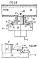
- Figure 2A is an assembled view of the sensor assembly of Figure 1 installed in the associated vehicle gas directing component;
- Figure 2B is an expanded view of an engagement member of the sensor assembly of Figure 1 passing by an extension;
- Figure 3 is an expanded view of an alternate embodiment of a sensor assembly having an anti-rotation member designed according to the present invention;
- Figure 4A is an enlarged facial view of a sensor receipt member designed according to the present invention;
- Figure 4B is an enlarged facial view of an alternate embodiment of a sensor receipt member designed according to the present invention;
- Figure 5 is a sectional view of a gas directing component;
- Figure 6A is an expanded view of an engagement member of the sensor assembly designed in accordance with the present invention;
- Figure 6B is another expanded view of an engagement member of the sensor assembly designed in accordance with the present invention; and
- Figure 7 is yet another expanded view of an engagement member of the sensor assembly designed in accordance with the present invention.
-
- Figure 1 illustrates an exploded view of a
vehicle sensor assembly 10 and a vehicle gas directingcomponent 12 such as an air intake manifold. Thesensor assembly 10 includes asensor body 14 to retain asensor element 16 such as a temperature sensor, manifold absolute pressure (MAP) sensor, mass air flow sensor, potentiometer or other sensor element. As will be further described below, thesensor assembly 10 includes a plurality ofengagement members 18 which lock thesensor assembly 10 into asensor receipt member 20. - The
sensor receipt member 20 is preferably formed into the vehicle gas directingcomponent 12 such as an air intake manifold. As illustrated in Figure 1, thesensor receipt member 20 extends from anexternal wall 24 of thegas directing component 12 and provides anaperture 26 into the interior 28 of thegas directing component 12. To engage thesensor assembly 10,extensions 30 protrude from thesensor receipt member 20. Eachextension 30 includes aslot 32 which receives a segment of theengagement members 18. - The
sensor body 22 includes a locatingsegment 34 which fits within theaperture 26 and defines aprimary axis 35. Preferably, aseal 33 such as an O-ring is fitted to agroove 37 in the locatingsegment 34 to assure an air-tight fit between the locatingsegment 34 and theaperture 26. - Each of the
engagement members 18 define asecondary axis 36 displaced from theprimary axis 35. Theengagement members 18 each include afirst segment 38 which is receivable within a correspondingextension 30slot 32. Anenlarged segment 40 of eachengagement member 18 is preferably sized greater than theslot 32 to retain theengagement member 18 within theextension 30. In this disclosed embodiment, theengagement member 18 is substantially spherical in shape, however, other configurations are contemplated within the present invention. - Referring to Figure 2A, the
sensor assembly 10 is illustrated in an installed position. To install thesensor assembly 10, the locatingsegment 34 is initially inserted within theaperture 26. Thesensor assembly 10 is then pressed in the direction of arrow I along theprimary axis 35 until theenlarged segment 40 of eachengagement member 18 encounters an associatedextension 30. By providing additional force in the direction of arrow I, contact between theenlarged segment 40 of eachengagement member 18 and eachextension 30 forces theengagement members 18 to spread outward from their normal position along their secondary axis 36 (Figure 2A). Because theenlarged segment 40 is preferably low resistance such as the disclosed spherical shape, minimal additional force is required to force theenlarged segment 40 around theextensions 30. - Further force in the direction of arrow I allows the
enlarged segments 40 to pass by theextensions 30. Thefirst segment 38 of theengagement members 18 can then snap into theslots 32 and lock thesensor assembly 10 into the installed position. Because theenlarged segment 40 preferably cannot fit through theslot 32, great force is required to remove the sensor assembly. Thus, although no tools and only a minimum of force is required to install thesensor assembly 10, a much greater force is required to remove it. - Additional alignment and anti-rotation features can be further incorporated into the
sensor assembly 10. As illustrated in Figure 3, aslot 42 can be located within theaperture 26 which receives a correspondingtab 44 on the sensor assembly. Theslot 42 andtab 44 preferably assists in the alignment of theengagement member 18 with theextensions 30. In addition, thetab 44 can be located to remain within the slot upon full insertion of thesensor assembly 10. By maintaining thetab 44 within theslot 42, thesensor assembly 10 is provided with an anti-rotation retention feature that does not wholly rely upon theengagement members 18. - Other installation features may also be provided. A
radial flange 46 preferably extends from the locatingsegment 34. Theflange 46 assists in the installation of the sensor assembly by preventing thesensor assembly 10 from being forced too deep into theaperture 26. Theflange 46 may further be used to axially compress aseal 48 between theflange 46 and aface 49 of thesensor receipt member 20. - Referring to Figure4A, one disclosed embodiment illustrates a facial view of a
sensor receipt member 50 having anaperture 52. Theextensions 54 includeslots 56 which do not continue for the full length of theextensions 54. In other words, theslots 56 do not continue to the outer diameter of thesensor receipt member 50. Accordingly, theextensions 54 are stiffer than a sensor receipt member 50' having extensions 54' and slots 56' which do continue for the full length of the extensions 56' (Figure 4B). - As illustrated in Figure 4A, an additional set of
extensions 54a are provided. Theadditional extensions 54a assure that should anextension 54 be broken off, for example during removal of the sensor assembly, theadditional extension 54a allow for the immediate reinstallation of the sensor assembly without the necessity of repair of replacement of the entire gas directing component. - Referring to Figure 5, an alternate embodiment of a
sensor receipt member 60 is provided. As illustrated in the sectional view of Figure 5, thesensor receipt member 60 extends from anexternal wall 62 of agas directing component 64. However, thesensor receipt member 60 is substantially recessed below anouter surface 66 of thegas directing component 64. Thesensor receipt member 60 is thereby additionally protected from inadvertent damage. - Referring to Figure 6A, another disclosed embodiment of an
engagement member 66 according to the present invention is provided. The disclosedengagement member 66 includes a substantially cylindricalenlarged segment 68. The cylindricalenlarged segment 68 engages with anextension 70 havingslot 71 as described above. - Referring to Figure 6B, another disclosed embodiment of an
engagement member 72 according to the present invention is provided. The disclosedengagement member 72 includes a substantially airfoil shapedenlarged segment 73 which engages with anextension 74 as described above. In addition, a chamfered edge 75 on theextension 74 may be additionally provided. The relationship between the chamfered edge 75 and airfoil shapedenlarged segment 73 may be further adjusted to alter the engagement force. Referring to Figure 7, yet another disclosed embodiment illustrates a top view of asensor receipt member 76. Theextensions 80 include aslot 82 having one ramp-shapedside 84. By providingslot 82 with a rampedside 84 on eachextension 80, the sensor assembly can be twisted in the direction of arrow R to be removed. As illustrated, afirst segment 88 of theengagement member 86 are forced outward along the rampedside 84 to disengage theengagement member 86. Thus, although theengagement member 86 can not be pulled out of theextension 80 because of theenlarged segment 87, it can be rotated out of theslot 82, when rotated in the direction of arrow R thereby using the rampedside 84 to force theengagement member 86 to be spread outward. Such an arrangement is particularly advantageous in recessed or difficult to reach locations. - The foregoing description is exemplary rather than limiting in nature. Many modifications and variations of the present invention are possible in light of the above teachings. The preferred embodiments of this invention have been disclosed, however, one of ordinary skill in the art would recognize that certain modifications are possible that would come within the scope of this invention. It is, therefore, to be understood that within the scope of the appended claims, the invention may be practiced otherwise than as specifically described. For that reason the following claims should be studied to determine the true scope of protection given for this invention.
Claims (19)
- A sensor assembly for a vehicle gas directing component comprising:a sensor receipt member, said sensor receipt member including a plurality of extensions, each of said extensions including a slot;a sensor body for insertion into said sensor receipt member, said sensor body defining a first axis; anda plurality of engagement members attached to said sensor body, each of said engagement members defining a secondary axis displaced from said primary axis, and each of said engagement members including a first segment receivable within one of said slots and an enlarged segment retainable by said extension.
- The sensor assembly as recited in claim 1, wherein said enlarged segment includes a substantially spherical portion.
- The sensor assembly as recited in claim 1, wherein said enlarged segment includes a substantially cylindrical portion.
- The sensor assembly as recited in claim 1, wherein said enlarged segment includes a substantially airfoil shaped portion.
- The sensor assembly as recited in claim 1, further comprising a key extending radially from said locating portion, said key receivable within a slot in said sensor receipt member to prevent rotation therebetween.
- The sensor assembly as recited in claim 1, wherein said plurality of extensions is more numerous than said plurality of engagement members.
- The sensor assembly as recited in claim 1, wherein said slot includes a first side and a second side, said first side being substantially parallel to said second side.
- The sensor assembly as recited in claim 1, wherein said slot includes a first side and a second side, said first side being substantially angled relative to said second side.
- The sensor assembly as recited in claim 1, wherein said sensor receipt member is substantially recessed relative to an outer wall of said gas directing component.
- The sensor assembly as recited in claim 1, wherein said first segment is flexible such that said enlarged portion can deflect around said extensions, and said first segment can then move into said slot with said enlarged section positioned adjacent said slot.
- A sensor assembly for a vehicle gas directing component comprising:a sensor receipt member, said sensor receipt member including a plurality of extensions, each of said extensions including a slot;a sensor body having a locating portion for insertion into said sensor receipt member, said locating portion defining a first axis; anda plurality of engagement members attached to said sensor body, each of said engagement members defining a secondary axis displaced from said primary axis, and each of said engagement members including a first segment receivable within one of said slots and an enlarged segment retainable by said extension.
- The sensor assembly as recited in claim 11, wherein said enlarged segment includes a substantially spherical portion.
- The sensor assembly as recited in claim 11, wherein said enlarged segment includes a substantially cylindrical portion.
- The sensor assembly as recited in claim 11, wherein said enlarged segment includes a substantially airfoil shaped portion.
- The sensor assembly as recited in claim 11, wherein said first segment is flexible such that said enlarged portion can deflect around said extensions, and said first segment can then move into said slot with said enlarged section positioned adjacent said slot.
- An air intake manifold assembly comprising:a sensor receipt member attached to an air intake manifold, said sensor receipt member including a plurality of extensions, each of said extensions including a slot;a sensor body having a locating portion for insertion into said sensor receipt member, said locating portion defining a first axis; anda plurality of engagement members attached to said sensor body, each of said engagement members defining a secondary axis displaced from said primary axis, and each of said engagement members including a first segment receivable within one of said slots and an enlarged segment retainable by said extension.
- The sensor assembly as recited in claim 16, wherein said sensor receipt member is substantially recessed relative to an outer wall of said air intake manifold.
- The sensor assembly as recited in claim 16, wherein said enlarged segment includes a substantially airfoil shaped portion.
- The sensor assembly as recited in claim 16, wherein said first segment is flexible such that said enlarged portion can deflect around said extensions, and said first segment can then move into said slot with said enlarged section positioned adjacent said slot.
Applications Claiming Priority (2)
| Application Number | Priority Date | Filing Date | Title |
|---|---|---|---|
| US13382299P | 1999-05-12 | 1999-05-12 | |
| US133822P | 1999-05-12 |
Publications (3)
| Publication Number | Publication Date |
|---|---|
| EP1052490A2 true EP1052490A2 (en) | 2000-11-15 |
| EP1052490A3 EP1052490A3 (en) | 2001-09-05 |
| EP1052490B1 EP1052490B1 (en) | 2004-08-11 |
Family
ID=22460444
Family Applications (1)
| Application Number | Title | Priority Date | Filing Date |
|---|---|---|---|
| EP00109883A Expired - Lifetime EP1052490B1 (en) | 1999-05-12 | 2000-05-10 | Snap-in attachment arrangement |
Country Status (3)
| Country | Link |
|---|---|
| US (1) | US6539786B1 (en) |
| EP (1) | EP1052490B1 (en) |
| DE (1) | DE60012814T2 (en) |
Families Citing this family (4)
| Publication number | Priority date | Publication date | Assignee | Title |
|---|---|---|---|---|
| US20060267257A1 (en) * | 2005-05-24 | 2006-11-30 | Bfs Diversified Products, Llc | Air spring assembly with non-threaded connection |
| JP2007315792A (en) | 2006-05-23 | 2007-12-06 | Mitsubishi Electric Corp | Pressure sensor mounting structure |
| US9689357B2 (en) * | 2013-11-15 | 2017-06-27 | Quirt Evan Crawford | Method and apparatus for improving engine performance |
| JP7261689B2 (en) * | 2019-08-07 | 2023-04-20 | ナブテスコ株式会社 | Pressure sensor mounting adapters and sensors |
Family Cites Families (18)
| Publication number | Priority date | Publication date | Assignee | Title |
|---|---|---|---|---|
| GB801735A (en) * | 1956-01-21 | 1958-09-17 | Spinnfaser Ag | Devices for permitting the connection to pipes or conduits of a measuring device formeasuring values indicating the condition of media passing through or stationary in pipes, or conduits especially pipe carrying spinning solutions |
| JPH0442568Y2 (en) | 1985-06-19 | 1992-10-08 | ||
| US4842010A (en) * | 1988-10-18 | 1989-06-27 | General Motors Corporaion | Locking mechanism |
| AT394112B (en) | 1989-03-30 | 1992-02-10 | Avl Verbrennungskraft Messtech | PRESSURE SENSOR |
| US5201623A (en) | 1992-02-18 | 1993-04-13 | Emhart Inc. | Two stage rivet |
| US5317924A (en) * | 1992-07-13 | 1994-06-07 | Delco Electronics Corporation | Self-retaining, self-sealing pressure sensor |
| DE4334123C2 (en) * | 1993-10-07 | 2002-12-19 | Bosch Gmbh Robert | pressure sensor |
| US5355726A (en) * | 1994-01-03 | 1994-10-18 | Ford Motor Company | Housing for reducing back air flow to mass air flow sensors |
| DE4413488A1 (en) * | 1994-04-19 | 1995-10-26 | Leybold Ag | Vacuum-tight connection |
| JPH07287900A (en) | 1994-04-20 | 1995-10-31 | Mitsumi Electric Co Ltd | Elastic member mounting structure |
| JP3251775B2 (en) | 1994-06-15 | 2002-01-28 | 株式会社ニフコ | clip |
| DE4426102C2 (en) * | 1994-07-22 | 1997-07-10 | Bosch Gmbh Robert | Sensor carrier for a device for measuring the mass of a flowing medium and method for producing a sensor carrier |
| JP3323745B2 (en) * | 1996-07-25 | 2002-09-09 | 株式会社日立製作所 | Characteristic adjustment means of physical quantity detection device and heating resistance type air flow device |
| JP3656689B2 (en) | 1996-08-30 | 2005-06-08 | 株式会社デンソー | Elastic member for sensor mounting, sensor mounting structure using the same, and sensor mounting method therefor |
| KR200145406Y1 (en) | 1996-11-05 | 1999-06-15 | 호우덴코 | Housing structure of intake pipe pressure sensor for internal combustion engine |
| DE19715556B4 (en) | 1997-04-15 | 2012-05-10 | Gm Global Technology Operations Llc (N.D.Ges.D. Staates Delaware) | Arrangement of a sensor housing on a wall |
| JP3523022B2 (en) * | 1997-06-26 | 2004-04-26 | 株式会社日立製作所 | Heating resistor type air flow measuring device, intake system of internal combustion engine and control system of internal combustion engine |
| US6000427A (en) | 1998-10-19 | 1999-12-14 | Hutton; Peter B. | Manifold for use with dual pressure sensor units |
-
2000
- 2000-05-10 DE DE2000612814 patent/DE60012814T2/en not_active Expired - Lifetime
- 2000-05-10 EP EP00109883A patent/EP1052490B1/en not_active Expired - Lifetime
- 2000-05-11 US US09/569,207 patent/US6539786B1/en not_active Expired - Fee Related
Also Published As
| Publication number | Publication date |
|---|---|
| DE60012814D1 (en) | 2004-09-16 |
| EP1052490B1 (en) | 2004-08-11 |
| DE60012814T2 (en) | 2005-01-13 |
| EP1052490A3 (en) | 2001-09-05 |
| US6539786B1 (en) | 2003-04-01 |
Similar Documents
| Publication | Publication Date | Title |
|---|---|---|
| US5724946A (en) | Fuel rail and injector assembly | |
| EP1221022B1 (en) | Creep enhanced sensor attachment arrangement | |
| US5882367A (en) | Rotatable sealed filter outlet | |
| US5711550A (en) | Connecting device for pipelines | |
| US8097061B2 (en) | Elliptical seal interface for filter assembly | |
| US6523817B1 (en) | Interlocking vehicle body mount | |
| US9446333B2 (en) | Keyed thread engagement on spin-on filter element | |
| KR102240601B1 (en) | Keyed thread engagement on spin-on filter element | |
| EP2025925B1 (en) | Fuel damper fixing clip | |
| US6779406B1 (en) | Self-retaining pressure sensor assembly having notched seal retention flange | |
| US5265411A (en) | Attachment clip | |
| CA2068820A1 (en) | Means for mounting a fuel injector on a fuel rail | |
| US20030168856A1 (en) | Receiving part of a fluid plug-in coupling | |
| US5655795A (en) | Throttle body inlet duct | |
| WO1998027334A1 (en) | Fuel rail to fuel tube end compact connector | |
| US5653147A (en) | Expandable retainer for conduit end fitting | |
| EP1052490B1 (en) | Snap-in attachment arrangement | |
| US5070829A (en) | Primer bulb retainer for carburetor | |
| US8821185B2 (en) | Locking device for a connecting arrangement | |
| US6497158B1 (en) | Push on sensor attachment arrangement | |
| GB2307728A (en) | Snap mount throttle position sensor | |
| US6588389B1 (en) | Shift drum | |
| US20200386129A1 (en) | Filter Element of a Filter for Purifying Fluids, Insertion Adapter, and Filter | |
| US7051694B2 (en) | Sealing system for a shaft | |
| US20020043235A1 (en) | Clampless hose retainer mechanism |
Legal Events
| Date | Code | Title | Description |
|---|---|---|---|
| PUAI | Public reference made under article 153(3) epc to a published international application that has entered the european phase |
Free format text: ORIGINAL CODE: 0009012 |
|
| AK | Designated contracting states |
Kind code of ref document: A2 Designated state(s): AT BE CH CY DE DK ES FI FR GB GR IE IT LI LU MC NL PT SE Kind code of ref document: A2 Designated state(s): DE FR GB |
|
| AX | Request for extension of the european patent |
Free format text: AL;LT;LV;MK;RO;SI |
|
| PUAL | Search report despatched |
Free format text: ORIGINAL CODE: 0009013 |
|
| AK | Designated contracting states |
Kind code of ref document: A3 Designated state(s): AT BE CH CY DE DK ES FI FR GB GR IE IT LI LU MC NL PT SE |
|
| AX | Request for extension of the european patent |
Free format text: AL;LT;LV;MK;RO;SI |
|
| 17P | Request for examination filed |
Effective date: 20010809 |
|
| AKX | Designation fees paid |
Free format text: DE FR GB |
|
| RAP1 | Party data changed (applicant data changed or rights of an application transferred) |
Owner name: SIEMENS VDO AUTOMOTIVE INC. |
|
| 17Q | First examination report despatched |
Effective date: 20031126 |
|
| GRAP | Despatch of communication of intention to grant a patent |
Free format text: ORIGINAL CODE: EPIDOSNIGR1 |
|
| GRAS | Grant fee paid |
Free format text: ORIGINAL CODE: EPIDOSNIGR3 |
|
| GRAA | (expected) grant |
Free format text: ORIGINAL CODE: 0009210 |
|
| AK | Designated contracting states |
Kind code of ref document: B1 Designated state(s): DE FR GB |
|
| REG | Reference to a national code |
Ref country code: GB Ref legal event code: FG4D |
|
| REF | Corresponds to: |
Ref document number: 60012814 Country of ref document: DE Date of ref document: 20040916 Kind code of ref document: P |
|
| ET | Fr: translation filed | ||
| PLBE | No opposition filed within time limit |
Free format text: ORIGINAL CODE: 0009261 |
|
| STAA | Information on the status of an ep patent application or granted ep patent |
Free format text: STATUS: NO OPPOSITION FILED WITHIN TIME LIMIT |
|
| 26N | No opposition filed |
Effective date: 20050512 |
|
| PG25 | Lapsed in a contracting state [announced via postgrant information from national office to epo] |
Ref country code: FR Free format text: LAPSE BECAUSE OF NON-PAYMENT OF DUE FEES Effective date: 20060131 |
|
| REG | Reference to a national code |
Ref country code: FR Ref legal event code: ST Effective date: 20060131 |
|
| PGFP | Annual fee paid to national office [announced via postgrant information from national office to epo] |
Ref country code: GB Payment date: 20140521 Year of fee payment: 15 |
|
| PGFP | Annual fee paid to national office [announced via postgrant information from national office to epo] |
Ref country code: DE Payment date: 20140531 Year of fee payment: 15 |
|
| REG | Reference to a national code |
Ref country code: DE Ref legal event code: R119 Ref document number: 60012814 Country of ref document: DE |
|
| GBPC | Gb: european patent ceased through non-payment of renewal fee |
Effective date: 20150510 |
|
| PG25 | Lapsed in a contracting state [announced via postgrant information from national office to epo] |
Ref country code: GB Free format text: LAPSE BECAUSE OF NON-PAYMENT OF DUE FEES Effective date: 20150510 Ref country code: DE Free format text: LAPSE BECAUSE OF NON-PAYMENT OF DUE FEES Effective date: 20151201 |