EP1052487A2 - Method for measuring pressure higher than measurable range of presure measuring film - Google Patents
Method for measuring pressure higher than measurable range of presure measuring film Download PDFInfo
- Publication number
- EP1052487A2 EP1052487A2 EP00303974A EP00303974A EP1052487A2 EP 1052487 A2 EP1052487 A2 EP 1052487A2 EP 00303974 A EP00303974 A EP 00303974A EP 00303974 A EP00303974 A EP 00303974A EP 1052487 A2 EP1052487 A2 EP 1052487A2
- Authority
- EP
- European Patent Office
- Prior art keywords
- pressure
- measuring film
- pressure measuring
- distribution curve
- film
- Prior art date
- Legal status (The legal status is an assumption and is not a legal conclusion. Google has not performed a legal analysis and makes no representation as to the accuracy of the status listed.)
- Withdrawn
Links
- 238000000034 method Methods 0.000 title claims abstract description 38
- 238000009826 distribution Methods 0.000 claims abstract description 63
- 238000009530 blood pressure measurement Methods 0.000 claims description 15
- 239000003094 microcapsule Substances 0.000 claims description 12
- 229920001875 Ebonite Polymers 0.000 claims description 5
- 230000003247 decreasing effect Effects 0.000 claims description 2
- 230000003287 optical effect Effects 0.000 claims 2
- 238000010586 diagram Methods 0.000 description 13
- 238000005259 measurement Methods 0.000 description 5
- 239000003822 epoxy resin Substances 0.000 description 4
- 229920000647 polyepoxide Polymers 0.000 description 4
- 235000010724 Wisteria floribunda Nutrition 0.000 description 3
- 239000011521 glass Substances 0.000 description 3
- 238000002485 combustion reaction Methods 0.000 description 2
- 239000000463 material Substances 0.000 description 2
- 230000001154 acute effect Effects 0.000 description 1
- 238000006243 chemical reaction Methods 0.000 description 1
- 239000011248 coating agent Substances 0.000 description 1
- 238000000576 coating method Methods 0.000 description 1
- 230000006835 compression Effects 0.000 description 1
- 238000007906 compression Methods 0.000 description 1
- 238000009792 diffusion process Methods 0.000 description 1
- 238000006073 displacement reaction Methods 0.000 description 1
- 239000003365 glass fiber Substances 0.000 description 1
- 230000002093 peripheral effect Effects 0.000 description 1
Images



Classifications
-
- G—PHYSICS
- G01—MEASURING; TESTING
- G01L—MEASURING FORCE, STRESS, TORQUE, WORK, MECHANICAL POWER, MECHANICAL EFFICIENCY, OR FLUID PRESSURE
- G01L1/00—Measuring force or stress, in general
- G01L1/24—Measuring force or stress, in general by measuring variations of optical properties of material when it is stressed, e.g. by photoelastic stress analysis using infrared, visible light, ultraviolet
Definitions
- the present invention relates to a method for measuring a pressure applied between opposing surfaces using a pressure measuring film, particularly a method for measuring a pressure higher than a measurable pressure range of the pressure measuring film.
- the present invention also relates to a pressure measurement apparatus for direct use in carrying out the method.
- the Prescale is comprising of microcapsules containing a color former and a color developer coated on the same surface of a support, or on different supports.
- the microcapsules at the portion subjected to pressure is destroyed to cause the color former released from the ruptured microcapsules to react to the developer so as to develop a predetermined color (e.g., red) by chemical reaction.
- a predetermined color e.g., red
- the pressure applied can be determined by measuring the developed color density.
- the pressure measuring film is able to measure different pressure range by using microcapsules which have different wall thicknesses to be ruptured upon application of different pressure levels. A plurality of types of pressure measuring films for different measurable pressure range are prepared, and the film with an appropriate pressure range is selected and used depending on the pressure to be measured.
- the pressure level to be measured is higher than the measurable pressure range of the pressure measuring film, the pressure cannot correctly be measured with this pressure measuring film.
- the cylinder block and cylinder head of a reciprocating engine (internal combustion engine) with a gasket disposed therebetween are clamped by a cylinder head bolt.
- this pressure becomes larger than the pressure range of the pressure measuring film for the highest pressure use.
- the measurable pressure range of an available pressure measuring film (Prescale) for high-pressure is 50 to 130 MPa (additionally, 1 MPa is nearly equal to 10.2 kgf/cm 2 ), while the bonding pressure of the cylinder block and cylinder head is about 1.8 ton/cm 2 (nearly equal to 176.5 MPa). Therefore, even when the pressure measuring film for high-pressure is used, it can only be judged that the detected pressure is higher than the maximum value (130 MPa) of the measurable pressure range. The color density at the portion to which such high pressure is applied reaches up to the maximum density and saturates in this density level. Accordingly, the actual maximum bonding pressure cannot correctly be measured, which is a large obstruction during development of the engine and gasket.
- a first object at least of a preferred embodiment, is to provide a pressure measurement method which can measure a pressure higher than a measurable pressure range using a pressure measuring film.
- a second object again at least of a preferred embodiment, is to provide a pressure measurement apparatus for direct use in carrying out this method.
- a method for measuring a pressure applied between opposing first and second surfaces using a pressure measuring film comprising steps of;
- the point or linear contact portion on the second surface does not restrictedly mean the point or linear shape, and of course has a certain degree of area.
- a protrusion disposed along a circle surrounding a cylinder periphery forms the linear contact portion.
- the top surface of the gasket including the protrusion constitutes the second surface of the present invention.
- the bottom surface of the cylinder head onto which the protrusion is abutted and pressed constitutes first surface of the present invention.
- one of the pressing surfaces disposed opposite to each other is flatter than the other, and this one (i.e., the first surface) is abutted and contacted with the other pressing surface (i.e., the second surface) in an acute manner.
- the pressure measurement method of the present invention can be applied.
- a film can be used which is obtained by forming a layer of a microcapsulated color former and a layer of a color developer on a support (film). By application of pressure, the microcapsules are destroyed to release the color former from the ruptured microcapsules. The released color former is adsorbed to the developer and a color is developed by chemical reaction.
- "Prescale” (tradename) sold by Fuji Photo Film Co., Ltd. can be used.
- the density distribution on a line crossing the colored image which corresponds the contact portion of point or linear contact is measured to obtain the pressure distribution along the crossing line.
- the maximum pressure P H between the pressing surfaces can be obtained by using the area S E surrounded by the pressure distribution curve and the contact length L of the contact portion.
- the area S E surrounded by the pressure distribution curve is considered to correspond to the work amount (pressure ⁇ compression amount) by pressing, or to the amount obtained by integrating this work amount by a coefficient for correcting the influence by an elastic sheet. Consequently, the maximum pressure applied between the pressing surfaces can be determined using this area S E and contact length L.
- the contact length L used herein may be detected from the colored image obtained when the same pressure measuring film (second pressure measuring film) is held and pressed between the pressing surfaces without using any elastic sheet.
- the contact length L may also be obtained as follows.
- the pressure measuring films of the same standard are held between both surfaces of the elastic sheet and two pressing surfaces, and the contact length L is obtained from the colored image formed on the pressure measuring film (second pressure measuring film) which directly contacts to the point/linear contact portion of the pressing surface (second surface).
- the pressure measuring film (second pressure film) having the same characteristics as that of the above-described pressure measuring film (first pressure measuring film) is pressed between the pressing surfaces without using the elastic sheet, and a second pressure distribution curve F may be obtained from the resulting color development state.
- the pressure distribution curve is obtained from the colored image formed on the pressure measuring film by using the elastic sheet as described above and thus obtained curve is used as a first pressure distribution curve E
- the aimed maximum pressure can be obtained by enlarging or extrapolating the second pressure distribution curve toward the maximum value so that the area S F surrounded by the enlarged second pressure distribution curve substantially becomes the same as the area S E of the first pressure distribution curve.
- the respective pressure measuring films may be held and pressed between both sides of the elastic sheet and two pressing surfaces.
- the pressure measuring film coming in contact with the point/linear contact portion of the second pressing surface is used as the second pressure measuring film, and the other film can be used as the first pressure measuring film.
- the necessary pressure distribution curves can be obtained by once pressing the first and second pressure measuring films between the pressing surfaces, measurement precision is enhanced.
- a hard rubber sheet may be used as the elastic sheet, but when the pressure is particularly large, hard glass epoxy resin having less elastic deformability than that of hard rubber may be used. If between both the pressing surfaces, the pressure applied from the second pressing surface including a more acutely protruded contact portion is dispersed in the elastic sheet, and the pressure transmitted and applied to the pressure measuring film is reduced, such sheet can be used as the elastic sheet in the pressure measurement method of the present invention.
- a pressure measurement apparatus for use in the method described above, the apparatus comprising:
- a cylinder block 10 of a reciprocating engine, and a cylinder head 12 are firmly clamped and fixed to each other by a cylinder head bolt (not shown) via a gasket 14.
- a gasket 14 As shown in Figs. 2, 3, circular openings 14A are formed facing to respective cylinders 10A, while a circular protrusion 14B is disposed along the peripheral edge of the opening 14A on the top surface (the surface facing to the cylinder head 12).
- the protrusion 14B forms a linear contact portion in the present invention, and this protrusion 14B is strongly pressed against the under surface 12A of the cylinder head 12 to prevent the leakage of the internal pressure from the combustion chamber. Therefore, the under surface 12A of the cylinder head 12 and the top surface 14C of the gasket 14 forms first and second pressing surfaces in the present invention, respectively.
- an elastic sheet 16 and a pressure measuring film 18 are laid on the top surface 14C of the gasket 14, finally the cylinder head 12 is laid and the whole assembly is strongly clamped and bonded by the cylinder head bolt (not shown).
- the elastic sheet 16 is a sheet formed of hard rubber, epoxy resin reinforced by glass fiber (glass epoxy resin), or the like, and a sheet with an appropriate elasticity and thickness is selected depending on the magnitude of a clamping force (that is, a pressing force) applied between pressing surfaces 14C and 12A.
- a film obtained by coating a microcapsulated color former and a color developer on a support can be used.
- film "Prescale” (tradename) presented by Fuji Photo Film Co., Ltd. is suitable.
- This film includes a mono-sheet type in which a layer of microcapsules containing the color former and a layer of the color developer are overlaid and coated on one sheet of support, and a two-sheet type in which both are separately applied to the supports and the supports are overlaid during use to join the microcapsulated color former to the developer. Either type can be used in the present invention.
- the elastic sheet 16 and pressure measuring film 18 are pressed between two pressing surfaces 14C and 12A.
- the protrusion 14B of the gasket 14 presses the elastic sheet 16 in a concentrated manner, and the pressure is diffused and transmitted to the pressure measuring film 18 as shown by a dotted line A of Fig. 3.
- the pressure applied to the pressure measuring film 18 is dispersed and the pressure distribution is substantially in a round mountain shape as shown by a dotted line B.
- a circular color development pattern or colored image C appears along the periphery of the cylinder 10A as shown in Fig. 4.
- the hardness and thickness of the elastic sheet 16 are set so that the pressure (per unit area) applied to the pressure measuring film 18 enters the measurable pressure range of the film 18.
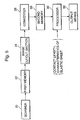
- the density distribution of the colored image C is read by a scanner 20 shown in Fig. 5.
- the read image is stored in a first memory 22.
- the image running along a straight line D-D crossing the colored image C is cut out from the read image by an image cutout section 24.
- a converter 26 converts the color density into the pressure value using a separately prepared table or calibration graph which shows the relationship between the color density and the pressure applied to the pressure measuring film, and obtains a pressure distribution E (Fig. 4B) along the straight line D-D from the density change of the cut out image.
- the obtained pressure distribution is stored in a second memory 28.
- the abscissa D-D indicates the coordinate of the length direction of the crossing line D-D shown in Fig. 4A, and the ordinate P indicates the pressure.
- the maximum pressing force P H which is larger than the maximum pressure P M of the measurable pressure range of the pressure measuring film 18.
- the contact length L By inputting the contact length L in an appropriate method, and setting the area of a rectangle L ⁇ H to be equal to S E , the height H is obtained.
- the correction coefficient indicating the influence by the thickness and hardness of the elastic sheet 16 may be added to the above described formula.
- the height H may be obtained in other methods.
- the state of diffusion of the pressure applied to the elastic sheet 16 from the protrusion (linear contact portion) 14B changes, for example, by the thickness, hardness and other characteristics of the elastic sheet 16. Therefore, conversely, when the thickness, hardness, and other characteristics of the elastic sheet 16 are known, the actual pressure distribution curve F at the position of the protrusion 14B can be estimated from the detected pressure distribution curve E.
- Fig. 4B shows this estimated pressure distribution curve F.
- an intersection of the curves E and F is set as a , and a slant-line area S 1 held between the curves E and F below this intersection a is set to be equal to a slant-line area S 2 held between the curves E and F above the intersection a .
- an appropriate correction coefficient may be added to perform correction.
- the maximum pressing force P H obtained in this manner is transferred to an output means or device 32, such as a display or a printer for outputting the maximum pressure P H .
- the maximum pressure P H is obtained based on the contact length L and the characteristics of the elastic sheet 16, but another pressure measuring film (second pressure measuring film) 40 of the same standard as that of the pressure measuring film 18 may be used to estimate the maximum pressure P H .
- the pressure measuring film 18 is used as the first pressure measuring film in the second embodiment as described hereinafter.
- Figs. 6A to 6D are diagrams showing a method of using the first and second pressure measuring films 18, 40 to perform pressure measurement.
- Fig. 6A is a diagram showing the arrangement of the respective films 18, 40
- Fig. 6B is a diagram showing the pressure distribution curve E detected from the first pressure measuring film 18
- Fig. 6C is a diagram showing the pressure distribution curve F detected from the second pressure measuring film 40
- Fig. 6D is a diagram showing a method of using both curves E and F to obtain the maximum pressure P H .
- the abscissa D-D indicates the position along the straight line which crosses the color development pattern
- the ordinate indicates the pressure P.
- the second pressure distribution curve F shows the pressure up to the maximum pressure P M of the measurable pressure range of the second pressure measuring film 40.
- the second pressure measuring film 40 is held between the gasket 14 and the elastic sheet 16, and pressed together with the first pressure measuring film 18, and the color development pattern is simultaneously formed. Subsequently, these color development patterns are read by the scanner 20 shown in Fig. 5 and stored in the first memory 22.
- the image cutout section cuts out the image of the position corresponding to the same crossing line D-D from this image, and the respective pressure distributions are obtained by the converter 26 and stored in the second memory 28.
- the processor 30 overlaps two pressure distribution curves E and F as shown in Fig. 6D, and enlarges or expands the shape of the curve F upward.
- the shape of an expanded curve F O is determined so that the area S FO surrounded by the expanded curve F O and abscissa D-D substantially agrees with the area S E surrounded by the first pressure distribution curve E and abscissa D-D.
- the height H of the upwardly-expanded second pressure distribution curve F O indicates the maximum pressure P H .
- the second pressure measuring film 40 When the second pressure measuring film 40 is pressed simultaneously with the first pressure measuring film 18 in this manner, it is possible to set the pressure in total applied to the films 40, 18 to be the same and enhance the measurement precision. However, by separately pressing both films 40, 18, the respective color development patterns may separately be obtained. In this case, it is of course necessary to change the gasket 14 and set the same clamping force. When the gasket 14 is pressed, this method is not appropriate because the gasket 14 is deformed by pressing and it is difficult to provide the same clamping force, but the method is appropriate when the pressure between the pressing surfaces is measured by a press apparatus in which the pressing force is always constant without using the gasket or other deformable materials.
- the pressure applied to the pressure measuring film is placed in the measurable pressure range by holding and pressing the elastic sheet between the pressing surface having the point/linear contact portion and the pressure measuring film.
- the pressure distribution obtained from the colored image formed on the pressure measuring film is used to determine the maximum pressure applied between the pressing surfaces. Accordingly, it is possible to measure the large pressure which falls in or exceeds the measurable pressure range of the pressure measuring film.
- the film whose color development state e.g., color and density
- the film obtained by applying the microcapsulated color former and the color developer to one sheet of support or separate sheets of supports is convenient for handling.
- There can be various methods of obtaining the maximum pressure from the color development state of the pressure measuring film. For example, by obtaining the pressure distribution on the line crossing the contact portion from the color development state of the film, and using the area S E of the pressure distribution curve and the contact length L on the same line crossing the contact portion, the maximum pressure P H can be calculated by the following equation: S E L ⁇ P H .
- the maximum pressure P H can relatively easily be estimated according to the method.
- the contact length L is assumed to be substantially determined by the shape of the contact portion and material of the elastic sheet, the pressing force, etc., the contact length can be inputted as a predetermined constant value in advance. However, in the case in which the pressing can be repeated with a constant pressing force, this contact length L may be obtained from the colored image formed on the second pressure measuring film which is held and pressed between the pressing surfaces without using the elastic sheet, and the measurement precision is enhanced in this case.
- the second pressure measuring film used in this case when the film having the same characteristics as that of the pressure measuring film (first pressure measuring film) for pressing via the elastic sheet is used, the measurement precision is further enhanced.
- the maximum pressure P H can be detected.
- the color development pattern can be formed on both films by single pressing operation, the measurement precision is further enhanced.
- the method may comprise comparing the respective pressure distribution curves E, F detected by the first and second pressure measuring films to obtain the maximum pressure P H .
- the maximum pressure can be estimated from the height of the enlarged second pressure distribution curve F O .
- the precision is further enhanced.
- the second pressure measuring film may be pressed without using the elastic sheet, but the first and second pressure measuring films may be overlaid on both sides of the elastic sheet and simultaneously pressed. Also in this case, since the pressing conditions for both films are the same, the precision is further enhanced, and additionally the operation is facilitated.
- the elastic sheet a hard rubber sheet is easily obtainable and convenient, but harder sheets such as a glass epoxy resin sheet are also suitable depending on the pressure range to be measured.
- the pressure measurement apparatus for direct use in carrying out the method of the present invention can be obtained.
Landscapes
- Physics & Mathematics (AREA)
- General Physics & Mathematics (AREA)
- Force Measurement Appropriate To Specific Purposes (AREA)
- Measuring Fluid Pressure (AREA)
Abstract
Description
Claims (11)
- A method for measuring a pressure applied between opposing first and second surfaces using a pressure measuring film, the first surface being flatter than the second surface, the second surface having a contact portion to contact with the first surface in point contact or linear contact, comprising steps of;providing the pressure measuring film between said first and second surfaces, the pressure measuring film causing a pressurized portion thereof to develop a color;disposing an elastic sheet between said second surface and said pressure measuring film;applying the pressure between said first and second surfaces with holding said pressure measuring film and said elastic sheet therebetween;detecting a colored image formed on said pressure measuring film to obtain a pressure distribution curve; anddetermining a maximum pressure applied between said first and second surfaces based on the pressure distribution curve;wherein the pressure applied to said pressure measuring film is decreased as compared with the case in which the elastic sheet is not used.
- A method as claimed in claim 1,
wherein a measurable pressure range of said pressure measuring film is lower than the maximum pressure applied between said first and second surfaces, and the pressure applied to said pressure measuring film is placed into the measurable pressure range by disposing the elastic sheet intervened between said second surface and said pressure measuring film. - A method as claimed in claim 1 or 2, wherein said pressure distribution curve is obtained from a density distribution along a crossing line which crosses the colored image formed on the pressure measuring film; and wherein the maximum pressure applied between the first and second surfaces is calculated by following formula;PH is the maximum pressure applied between the first and second surfaces;SE is an area surrounded by said pressure distribution curve; andL is a contact length which is a length of the contact portion of the second surface to the first surface and is along said crossing line.
- A method as claimed in claim 3, wherein said contact length of the contact portion is detected from a colored imaged formed on a second pressure measuring film which is disposed and pressed between the first and second surfaces without using any elastic sheet.
- A method as claimed in claim 3,wherein a second pressure measuring film is also disposed between said first surface and said elastic sheet and the pressure is applied between the first and second surfaces with holding said pressure measuring film, said elastic sheet and said second pressure measuring sheet therebetween; andwherein said contact length of the contact portion is obtained from a colored image formed on said second pressuring film.
- A method as claimed in claim 1, further comprising;providing a second pressure measuring film, which has a characteristics same as that of said pressure measuring film, between the first and second surfaces;applying the pressure between the first and second surfaces with holding the second pressure measuring film therebetween; anddetecting a colored image formed on the second pressure measuring film to obtain a second pressure distribution curve;wherein said second pressure distribution curve is enlarged toward the maximum value of a pressure measurement range so that an area surrounded by the enlarged second pressure distribution curve is equal to an area surrounded by said pressure distribution curve of claim 1, and a height value of the enlarged second pressure distribution curve is read as the maximum pressure applied between the first and second surfaces.
- A method as claimed in claim 1,wherein a second pressure measuring film, which has a characteristics same as that of said pressure measuring film, is additionally disposed between the first surface and said elastic sheet, and the pressure is applied between the first and second surfaces with maintaining said first pressure measuring film, the elastic sheet and said second pressure measuring film therebetween;wherein a second pressure distribution curve is obtained from a colored image formed on the second pressure measuring film;and wherein said second pressure distribution curve is enlarged toward the maximum value of a pressure measurement range so that an area surrounded by the enlarged second pressure distribution curve is equal to an area surrounded by said pressure distribution curve of claim 1, a height value of the enlarged second pressure distribution curve is read as the maximum pressure applied between the first and second surfaces.
- A method as claimed in claim 1, wherein said pressure measuring film comprises a color developer and microcapsules containing a color former coated on the same surface of a support, and wherein the color former released from the microcapsules ruptured by an application of a pressure is adsorbed to the developer so as to develop a color, and an optical density of developed color increases in proportion with the pressure applied.
- A method as claimed in claim 1, wherein said pressure measuring film comprises a layer of microcapsules containing a color former coated on a support, and a layer of a color developer coated on a different support so as to oppose to the layer of microcapsules; and wherein the color former released from the microcapsules ruptured by an application of a pressure is adsorbed to the developer so as to develop a color, and an optical density of developed color increases in proportion with the pressure applied.
- A method as claimed in any preceding claim, wherein the elastic sheet is a hard rubber sheet.
- A pressure measurement apparatus for use in the method of claim 1, the apparatus comprising:a scanner for reading the colored image formed on a pressure measuring film to which a pressure is applied to develop color;a first memory for storing the image read by the scanner;an image cutout section for obtaining an image on a line crossing a contact portion of point contact or linear contact from the read image;a converter for obtaining a pressure distribution from the image cut out by the image cutout section;a second memory for storing the pressure distribution obtained by the converter;a processor for using the pressure distribution stored in the second memory to obtain a maximum pressure applied between surfaces; andan output means for outputting an operation result obtained by the processor.
Applications Claiming Priority (2)
| Application Number | Priority Date | Filing Date | Title |
|---|---|---|---|
| JP12949599A JP3911363B2 (en) | 1999-05-11 | 1999-05-11 | Pressure measuring method and apparatus |
| JP12949599 | 1999-05-11 |
Publications (2)
| Publication Number | Publication Date |
|---|---|
| EP1052487A2 true EP1052487A2 (en) | 2000-11-15 |
| EP1052487A3 EP1052487A3 (en) | 2003-05-14 |
Family
ID=15010902
Family Applications (1)
| Application Number | Title | Priority Date | Filing Date |
|---|---|---|---|
| EP00303974A Withdrawn EP1052487A3 (en) | 1999-05-11 | 2000-05-11 | Method for measuring pressure higher than measurable range of presure measuring film |
Country Status (3)
| Country | Link |
|---|---|
| US (1) | US6564641B1 (en) |
| EP (1) | EP1052487A3 (en) |
| JP (1) | JP3911363B2 (en) |
Families Citing this family (11)
| Publication number | Priority date | Publication date | Assignee | Title |
|---|---|---|---|---|
| FR2861847B1 (en) * | 2003-11-05 | 2006-03-31 | Eads Space Transportation Sa | EVALUATION METHOD FOR CONTROLLING IMPACT CONSEQUENCES ON A STRUCTURAL COMPOSITE MATERIAL PART |
| JP4836886B2 (en) * | 2007-07-05 | 2011-12-14 | 三菱電機株式会社 | Simple strain measurement tool and inspection device |
| US8640546B2 (en) * | 2011-09-12 | 2014-02-04 | Del Monte Corporation | Sensor for high pressure processing of articles |
| KR20140091033A (en) * | 2011-11-07 | 2014-07-18 | 베크만 컬터, 인코포레이티드 | Specimen container detection |
| US9916778B2 (en) * | 2015-08-06 | 2018-03-13 | Xerox Corporation | Backlighting effect for package displays |
| US20180306662A1 (en) * | 2017-04-24 | 2018-10-25 | Adam Burchett | System and Methods for Chromatic Pressure Gauges |
| JP7011471B2 (en) * | 2018-01-10 | 2022-01-26 | Ihi運搬機械株式会社 | A method for detecting a gripping state of a pressure measuring sheet and a rail clamp device for a track-traveling machine using the pressure measuring sheet. |
| JP7075589B2 (en) * | 2018-05-24 | 2022-05-26 | 地方独立行政法人鳥取県産業技術センター | Hand sensor device |
| JP6653006B1 (en) * | 2018-11-05 | 2020-02-26 | 株式会社テクサー | Pressure sensor sheet |
| JP7270926B2 (en) * | 2019-08-08 | 2023-05-11 | 戸田建設株式会社 | Lock bolt axial force detection fixture |
| WO2021235364A1 (en) | 2020-05-22 | 2021-11-25 | 富士フイルム株式会社 | Surface pressure analysis device, method, and program |
Family Cites Families (10)
| Publication number | Priority date | Publication date | Assignee | Title |
|---|---|---|---|---|
| US3469439A (en) | 1968-02-21 | 1969-09-30 | Sanford B Roberts | Means for measuring distributed forces using microcapsules |
| DE2260903A1 (en) * | 1972-12-13 | 1974-06-20 | Kalle Ag | METHOD FOR PRESSURE MEASUREMENT AND SUITABLE PRESSURE MEASURING BODIES |
| JPS50126479A (en) | 1974-03-26 | 1975-10-04 | ||
| JPS5288380A (en) * | 1976-01-20 | 1977-07-23 | Fuji Photo Film Co Ltd | Pressure measuring device |
| JPS6417534U (en) * | 1987-07-21 | 1989-01-27 | ||
| JP2755118B2 (en) * | 1993-09-01 | 1998-05-20 | 松下電器産業株式会社 | Thermal transfer recording method and intermediate transfer body |
| DE69532164T2 (en) * | 1994-08-18 | 2004-07-22 | Asahi Kasei Kabushiki Kaisha | HIGH DENSITY ETHYLENE POLYMERS AND METHOD FOR THE PRODUCTION THEREOF |
| JPH10170205A (en) * | 1996-12-12 | 1998-06-26 | Fuji Photo Film Co Ltd | Gap dimension detecting method and its detecting laminated body |
| JP3717136B2 (en) | 1998-05-21 | 2005-11-16 | 富士写真フイルム株式会社 | Gap size detection method, gap size detection laminate, and gap size detection device |
| US6033987A (en) * | 1999-01-15 | 2000-03-07 | Winbond Electronics Corp. | Method for mapping and adjusting pressure distribution of CMP processes |
-
1999
- 1999-05-11 JP JP12949599A patent/JP3911363B2/en not_active Expired - Fee Related
-
2000
- 2000-05-11 EP EP00303974A patent/EP1052487A3/en not_active Withdrawn
- 2000-05-11 US US09/568,496 patent/US6564641B1/en not_active Expired - Lifetime
Also Published As
| Publication number | Publication date |
|---|---|
| US6564641B1 (en) | 2003-05-20 |
| EP1052487A3 (en) | 2003-05-14 |
| JP2000321152A (en) | 2000-11-24 |
| JP3911363B2 (en) | 2007-05-09 |
Similar Documents
| Publication | Publication Date | Title |
|---|---|---|
| US6564641B1 (en) | Method for measuring pressure higher than measurable range of pressure measuring film | |
| EP0622622B1 (en) | Physical quantity detecting apparatus and internal combustion engine control apparatus each utilizing optical fiber | |
| US5469264A (en) | Optical measurement apparatus | |
| US20050285025A1 (en) | Optical noninvasive pressure sensor | |
| US4757195A (en) | Optical pressure sensor with pedestal mounted photoelastic element | |
| JP2006112842A (en) | Surface pressure distribution sensor | |
| EP0936455B1 (en) | Semiconductor pressure detecting device | |
| US6267014B1 (en) | Apparatus for sensing a load of pressure applied to a surface | |
| JP2005106513A (en) | Pressure sensor calibration method | |
| US7327473B2 (en) | Flatness tester for optical components | |
| US20040125465A1 (en) | Resin composition for lens sheet, lens sheet, and projection screen | |
| JP3410568B2 (en) | Pressure sensor | |
| JP2001185239A (en) | Mounting structure of temperature detection components | |
| JP3310137B2 (en) | Optical interference type fluid property measurement device | |
| JPH0694558A (en) | High pressure sensor | |
| JPH088436Y2 (en) | Optical sensor measurement medium | |
| KR200351396Y1 (en) | The Test Apparatus of The Optical Fingerprint Image Apparatus | |
| KR100538482B1 (en) | Resin composition for lens sheet, lens sheet, and projection screen | |
| JP2988077B2 (en) | Differential pressure measuring device | |
| JPH08189871A (en) | Differential pressure measuring device | |
| JPH06103232B2 (en) | Pressure sensitive foil | |
| EP0962744B1 (en) | Differential curvature transducer | |
| JP3771439B2 (en) | Load sensor | |
| CN116137679A (en) | Method for manufacturing optical sensor and optical sensor for detecting environment | |
| JPH05288620A (en) | Pressure sensor |
Legal Events
| Date | Code | Title | Description |
|---|---|---|---|
| PUAI | Public reference made under article 153(3) epc to a published international application that has entered the european phase |
Free format text: ORIGINAL CODE: 0009012 |
|
| AK | Designated contracting states |
Kind code of ref document: A2 Designated state(s): AT BE CH CY DE DK ES FI FR GB GR IE IT LI LU MC NL PT SE |
|
| AX | Request for extension of the european patent |
Free format text: AL;LT;LV;MK;RO;SI |
|
| PUAL | Search report despatched |
Free format text: ORIGINAL CODE: 0009013 |
|
| AK | Designated contracting states |
Designated state(s): AT BE CH CY DE DK ES FI FR GB GR IE IT LI LU MC NL PT SE |
|
| AX | Request for extension of the european patent |
Extension state: AL LT LV MK RO SI |
|
| 17P | Request for examination filed |
Effective date: 20030818 |
|
| AKX | Designation fees paid |
Designated state(s): DE FR GB |
|
| 17Q | First examination report despatched |
Effective date: 20060925 |
|
| RAP1 | Party data changed (applicant data changed or rights of an application transferred) |
Owner name: FUJIFILM CORPORATION |
|
| STAA | Information on the status of an ep patent application or granted ep patent |
Free format text: STATUS: THE APPLICATION IS DEEMED TO BE WITHDRAWN |
|
| 18D | Application deemed to be withdrawn |
Effective date: 20070206 |