EP1052479A2 - Piezoelectric oscillator and signal detection apparatus using the same - Google Patents
Piezoelectric oscillator and signal detection apparatus using the same Download PDFInfo
- Publication number
- EP1052479A2 EP1052479A2 EP00303646A EP00303646A EP1052479A2 EP 1052479 A2 EP1052479 A2 EP 1052479A2 EP 00303646 A EP00303646 A EP 00303646A EP 00303646 A EP00303646 A EP 00303646A EP 1052479 A2 EP1052479 A2 EP 1052479A2
- Authority
- EP
- European Patent Office
- Prior art keywords
- output
- vibration
- electrodes
- electrode
- driving
- Prior art date
- Legal status (The legal status is an assumption and is not a legal conclusion. Google has not performed a legal analysis and makes no representation as to the accuracy of the status listed.)
- Withdrawn
Links
Images






Classifications
-
- H—ELECTRICITY
- H10—SEMICONDUCTOR DEVICES; ELECTRIC SOLID-STATE DEVICES NOT OTHERWISE PROVIDED FOR
- H10N—ELECTRIC SOLID-STATE DEVICES NOT OTHERWISE PROVIDED FOR
- H10N30/00—Piezoelectric or electrostrictive devices
-
- G—PHYSICS
- G01—MEASURING; TESTING
- G01C—MEASURING DISTANCES, LEVELS OR BEARINGS; SURVEYING; NAVIGATION; GYROSCOPIC INSTRUMENTS; PHOTOGRAMMETRY OR VIDEOGRAMMETRY
- G01C19/00—Gyroscopes; Turn-sensitive devices using vibrating masses; Turn-sensitive devices without moving masses; Measuring angular rate using gyroscopic effects
- G01C19/56—Turn-sensitive devices using vibrating masses, e.g. vibratory angular rate sensors based on Coriolis forces
- G01C19/5607—Turn-sensitive devices using vibrating masses, e.g. vibratory angular rate sensors based on Coriolis forces using vibrating tuning forks
-
- G—PHYSICS
- G01—MEASURING; TESTING
- G01C—MEASURING DISTANCES, LEVELS OR BEARINGS; SURVEYING; NAVIGATION; GYROSCOPIC INSTRUMENTS; PHOTOGRAMMETRY OR VIDEOGRAMMETRY
- G01C19/00—Gyroscopes; Turn-sensitive devices using vibrating masses; Turn-sensitive devices without moving masses; Measuring angular rate using gyroscopic effects
- G01C19/56—Turn-sensitive devices using vibrating masses, e.g. vibratory angular rate sensors based on Coriolis forces
-
- G—PHYSICS
- G01—MEASURING; TESTING
- G01P—MEASURING LINEAR OR ANGULAR SPEED, ACCELERATION, DECELERATION, OR SHOCK; INDICATING PRESENCE, ABSENCE, OR DIRECTION, OF MOVEMENT
- G01P15/00—Measuring acceleration; Measuring deceleration; Measuring shock, i.e. sudden change of acceleration
- G01P15/02—Measuring acceleration; Measuring deceleration; Measuring shock, i.e. sudden change of acceleration by making use of inertia forces using solid seismic masses
- G01P15/08—Measuring acceleration; Measuring deceleration; Measuring shock, i.e. sudden change of acceleration by making use of inertia forces using solid seismic masses with conversion into electric or magnetic values
- G01P15/09—Measuring acceleration; Measuring deceleration; Measuring shock, i.e. sudden change of acceleration by making use of inertia forces using solid seismic masses with conversion into electric or magnetic values by piezoelectric pick-up
Definitions
- the present invention relates to a piezoelectric oscillator for use in gyroscopes, and more particularly, relates to a piezoelectric oscillator in which the number of electrodes is reduced, and relates to a signal detection apparatus using the same.
- Fig. 15A is a perspective view showing one of the surfaces of a conventional three-pronged tuning-fork-type piezoelectric oscillator.
- Fig. 15B is a perspective view showing the other surface thereof.
- Fig. 16 is a front view of a piezoelectric oscillator when the piezoelectric oscillator of Fig. 15A is viewed from the direction of arrow 16.
- the whole of an oscillator 1 is formed from a plate-shaped piezoelectric material, such as a piezoelectric ceramic or a quartz crystal; a tip portion thereof is separated by slots 1A and 1A, and three vibration legs 1a, 1b, and 1c are integrally formed therewith.
- the dielectric polarization direction of the piezoelectric material in each of the vibration legs 1a, 1b, and 1c is as indicated by the arrows in Fig. 16.
- the dielectric polarization direction is the same for the vibration legs 1b and 1c on both right and left sides. In the center vibration leg 1a, the dielectric polarization direction is laterally and vertically symmetrical with respect to the vibration legs 1b and 1c on the right and left.
- each of the vibration legs 1a, 1b, and 1c is formed with a pair of driving electrodes, 2 and 2, using a conductive material.
- the driving electrodes 2, 2, . . . extend up to the base end portion 1B of the oscillator 1, as shown in Fig. 15B.
- These driving electrodes 2, 2, . . . are connected to an AC driving power supply 3 by wiring (not shown), so that a driving voltage of the same electrical potential is supplied to the driving electrodes 2, 2, . . . , from the AC driving power supply 3.
- a pair of ground electrodes 4 and 4 are formed in each of the vibration legs 1b and 1c on the right and left, and one ground electrode 4 is formed in the center vibration leg 1a.
- the driving electrodes 4, 4, . . . extend to the base end portion 1B of the oscillator 1.
- a concentration pattern 4a is formed in the base end portion 1B, and all the ground electrodes 4 are connected to the concentration pattern 4a.
- Each of the ground electrodes 4 is at the ground potential by a wiring path (not shown).
- the driving electrodes 2, 2, . . . , and the ground electrodes 4, 4, . . . supply a driving voltage to the piezoelectric material which is a driving means.
- the vibration legs 1b and 1c on the right and left are driven to vibrate at the same phase in the X direction, and the vibration leg 1a in the center is driven to vibrate 180° out of phase opposite to that of the vibration legs 1b and 1c on right and left similarly in the X direction. That is, at a particular point in time, the amplitude of the vibration legs 1b and 1c on the right and left in the X direction and the amplitude of the vibration leg 1a in the X direction are opposite.
- the surface of the center vibration leg 1a is formed with a pair of detection electrodes 5a and 5b.
- the detection electrodes 5a and 5b extend more toward the front than the base end portion 1B in the back portion of the oscillator 1, and the detection electrodes 5a and 5b are formed integrally with land portions 5a1 and 5b1, respectively.
- each of the vibration legs 1a, 1b, and 1c has a vibration component in the Y direction due to a Coriolis force.
- the vibration legs 1b and 1c on both sides and the vibration leg 1a in the center since the phases of vibrations by a driving voltage are opposite, the phases of vibrations by a Coriolis force are opposite between the vibration legs 1b and 1c and the vibration leg 1a.
- the directions of the amplitude components, in the Y direction by the Coriolis forces, of the vibration legs 1b and 1c are the same, and the direction of the amplitude components in the Y direction, of the center vibration leg 1a is opposite to the direction of those of the vibration legs 1b and 1c.
- the detection electrodes 5a and 5b are formed on the same plane (the same vibration plane) of the center vibration leg 1a, and the piezoelectric material of the center vibration leg 1a functions as a Coriolis force detection means.
- the dielectric polarization directions of the piezoelectric materials in the portions where the detection electrodes 5a and 5b are formed are opposite to each other.
- a DC voltage corresponding to the phase difference ⁇ is detected by a phase difference detection means (not shown), the angular velocity ⁇ is determined from this DC voltage, and the angle is determined by numerical integration of this angular velocity ⁇ .
- the ground electrode 4 is provided on the narrow surface thereof, and moreover, this ground electrode 4 must be formed parallel to the detection electrode 5a and the detection electrode 5b in an area from the tip of the vibration leg 1a up to the base end portion 1B.
- An object of the present invention is to provide a piezoelectric oscillator in which the number of ground electrodes, which are required conventionally, can be reduced, simplifying a manufacturing process.
- Another object of the present invention is to provide a piezoelectric oscillator in which electrodes are arranged appropriately in vibration legs so that a phase difference can be reliably detected, and to provide a signal detection apparatus using this piezoelectric oscillator.
- a piezoelectric oscillator for outputting an angular velocity proportional to a Coriolis force in a rotating system
- the piezoelectric oscillator comprising: a vibration leg having a rectangular or square cross section; a pair of driving electrodes extending with a spacing therebetween in a direction in which the vibration leg is driven and in the direction of the length of the vibration leg in the plane extending in the driving direction; and a pair of output electrodes opposing the driving electrodes, extending in the direction of the length of the vibration leg, on a surface opposite to the surface on which the driving electrodes of the vibration leg are formed, wherein when driving power is supplied to the driving electrodes, the vibration leg is driven to vibrate by a piezoelectric effect, and an angular velocity component proportional to the Coriolis force is obtained from the pair of output electrodes by a piezoelectric effect.
- a pair of driving electrodes may be formed on the surface of one of the vibration legs, a pair of output electrodes may be formed on the other surface thereof, and no ground electrode need be provided between the driving electrodes and the output electrodes.
- a ground electrode for the purpose of grounding provided between a pair of output electrodes, can be omitted, it is possible to simplify the manufacturing process for forming electrodes.
- the oscillator is preferably provided with three-pronged vibration legs, the driving electrode and the output electrode are provided in all the vibration legs. and a driving signal is supplied between the driving electrode and the output electrode so that an angular velocity component proportional to a Coriolis force is detected from at least one set of output electrodes from among the output electrodes.
- the one set of output electrodes described above is, most preferably, a combination of a pair of output electrodes a and b provided in a center vibration leg (11v).
- they may be a combination of output electrodes a1 and b1 of a vibration leg (11u) on the left side, a combination of output electrodes a2 and b2 of a vibration leg (11w) on the right side, a combination of the output electrode a1 of the vibration leg (11u) on the left side and the output electrode b2 of the vibration leg (11w) on the right side, or a combination of the output electrode b1 of the vibration leg (11u) on the left side and the output electrode b2 of the vibration leg (11w) on the right side. It is also possible to make the outputs of the output electrodes a1 and a2 and the outputs of the output electrode b1 and b2 one set of output electrodes
- an output electrode other than the one set of output electrodes is fixed to an invariable potential.
- the invariable potential is a ground potential, and in addition, may also be a power-supply voltage, a midpoint potential (1/2 of the power-supply voltage), etc., as long as it is an electrical potential which does not vary.
- the output electrode is preferably provided at a position which is farthest from the center axis in the plane of the vibration legs.
- the present invention provides a signal detection apparatus comprising a piezoelectric oscillator comprising I/V (current/voltage) conversion means for converting a current output obtained from the output electrode into a voltage output, each of the output electrodes being grounded via an imaginary short-circuit in the I/V conversion means.
- I/V current/voltage
- a pair of driving electrodes are formed on one of the surfaces of a vibration leg, and a pair of output electrodes are formed on the other surface thereof.
- An AC driving signal is supplied to the driving electrode, and each pair of electrodes disposed in the vibration legs on both sides within the other surface are connected to a ground potential or to an invariable potential, making it possible to vibrate the vibration legs on both sides in the same phase.
- the electrode disposed in the center vibration leg is connected to the I/V conversion means comprising an operational amplifier, etc. Between an inversion terminal and a non-inversion terminal of the operational amplifier, which is a constituent of the I/V conversion means, the inversion terminal is at a ground potential due to the imaginary short-circuit. Thus, it is possible to cause the center vibration leg to be driven to vibrate even if a ground electrode is not formed as in the conventional case.
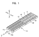
- Fig. 1 is a perspective view of a piezoelectric oscillator in a gyroscope.
- Fig. 2 is a front view of the piezoelectric oscillator when the piezoelectric oscillator of Fig. 1 is viewed from the direction of arrow 2.
- Fig. 3 is a front view showing the polarized state of another piezoelectric oscillator.
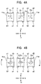
- Fig. 4A is a front view of each vibration leg when a vibration in the X direction is applied to the piezoelectric oscillator.
- Fig. 4B is a front view of each vibration leg when the piezoelectric oscillator is placed in a rotating system.
- a piezoelectric oscillator 11 As shown in Fig. 1, the whole of a piezoelectric oscillator 11 is formed by a plate member of a piezoelectric material formed from lead zirconate titanate (PZT) or a quartz crystal, and three vibration legs 11u, 11v, and 11w are formed so as to branch in the tip of the piezoelectric oscillator 11.
- PZT lead zirconate titanate
- the dielectric polarization direction of the piezoelectric material in each of the vibration legs 11u, 11v, and 11w is as indicated by the arrows in Fig. 2. That is, the dielectric polarization direction is the same for the vibration legs 11u and 11w on both right and left sides, and in the vibration leg 11v in the center, the dielectric polarization direction is symmetrical laterally and vertically with respect to the vibration legs 11u and 11w on the right and left.
- polarization from an output electrode b toward an output electrode a is set to P xa
- polarization from a driving electrode d toward a driving electrode c is set to P xb
- polarization from the output electrode b toward the driving electrode c is set to P ya
- polarization from the driving electrode d toward the output electrode a is set to P yb .
- electrodes b1, a1, b, a, b2, and a2 corresponding to the above-described driving electrodes are each printed and formed.
- the driving electrodes c1, d1, c, d, c2, and d2 are connected to an AC driving signal source E.
- the output electrodes b1, a1, b2, and a2 of the vibration legs 11u and 11w on both sides are connected to a ground potential (0 volt).
- the output electrodes b1, a1, b2, and a2 may be connected to a potential other than a ground potential, for example, a midpoint potential, if they are continuously fixed to a constant potential (invariable potential).
- the electrodes a and b of the center vibration leg 11v are output electrodes.
- the output electrodes a and b are connected to I/V conversion means 12 and 13, respectively, for converting a current output to a voltage output.
- the I/V conversion means 12 and 13 mainly comprise operational amplifiers 12A and 13A, respectively, so that current outputs I a and I b of the output electrodes a and b are converted into voltage outputs V a and V b , respectively.
- Non-inversion terminals (+ terminals) of the operational amplifiers 12A and 13A are grounded, and although the input impedances of the operational amplifiers 12A and 13A themselves are very large, the input impedances as the I/V conversion means 12 and 13 are very small.
- the inversion terminal reaches almost a ground potential. Therefore, even if a ground electrode G is provided between the electrodes a and b, and this round electrode G and the ground potential are not connected to each other as in the conventional case, the voltage outputs V a and V b can be obtained. Therefore, it is possible to omit the ground electrode G between the electrodes a and b.
- connection between the polarization arrangements of each of the vibration legs 11u, 11v, and 11w and the AC driving signal source may be, for example, that shown in Fig. 3. That is, when all the polarizations of each of the vibration legs 11u, 11v, and 11w are made in the same direction, for a driving signal to be supplied to the center vibration leg 11v and a driving signal to be supplied to the vibration legs 11u and 11w on both sides, power supplies E1 and E2, which are out of phase with each other by 180°, may be used. Alternatively, driving signals which are 180° out of phase may be generated from a driving signal of one AC driving signal source E, and these may be applied in a manner similar to that described above.
- each of the vibration legs 11u, 11v, and 11w bending deformation vibrations by a primary or several-order mode occurs in the X direction.
- the vibration legs 11u and 11w on both sides are driven in the same phase, and the center vibration leg 11v is driven in a phase which is different by ⁇ (180°) from those of the vibration legs 11u and 11w on both sides. That is, as shown in Fig. 4A, when the direction of the amplitude at a particular point in time of the vibration legs 11u and 11w on both sides is in the +X direction, the amplitude direction of the center vibration leg 11v is in the -X direction (the arrow of the dotted line). Also, when both the vibration legs 11u and 11w vibrate in the -X direction, the amplitude direction of the center vibration leg 11v is in the +X direction (the arrow of the solid line).
- each of the center axes of each of the vibration legs 11u, 11v, and 11w is set to O u , O v , and O w , respectively, the center axis O v of the center vibration leg 11v corresponds to the neutral axis O of the piezoelectric oscillator 11 when vibrations do not occur. Then, when vibrations occur in the X direction, the center axis O v of the center vibration leg 11v vibrates in the +X direction and in the -X direction about the neutral axis O.
- the vibration legs 11u and 11w on both sides vibrate in the X direction laterally symmetrical with respect to the neutral axis O, they have a role as balancers for the center vibration leg 11v to vibrate evenly from side to side.
- Fig. 5A is a front view showing the end surface of a vibration leg in the center.
- Fig. 5B shows the relationship of the relative distance between the center axis and an output electrode in a case in which a vibration in the X direction is applied to the vibration leg of Fig. 5A.
- Fig. 6A is a front view showing the end surface of the center vibration leg.
- Fig. 6B shows the relationship of the relative distance between the center axis and the output electrode in a case in which a vibration in the X direction is applied to the vibration leg of Fig. 6A and the piezoelectric oscillator is placed in a rotating system,
- the center vibration leg 11v when the center vibration leg 11v is taken note of, in a state in which vibrations occur in the X direction, the center axis O v of the center vibration leg 11v draws a trajectory which reciprocates between the coordinates ( ⁇ , 0) and (- ⁇ , 0) on the X axis.
- the trajectory is shown as a straight line which slants downward to the right, such as that shown in Fig. 5B.
- Fig. 5A when one of the electrodes a is regarded as being fixed and the relative distance L between this electrode a and the center axis O v in the trajectory is determined, the trajectory is shown as a straight line which slants downward to the right, such as that shown in Fig. 5B.
- Fig. 5A when one of the electrodes a is regarded as being fixed and the relative distance L between this electrode a and the center axis O v in the trajectory is determined, the trajectory is shown as a straight line which slants downward to the right,
- the driving electrode c side which is positioned at a side opposite thereto is in an expanded state. Also, the output electrode b side is in a state of shifting from an expanded state to a compressed state, and the driving electrode d side is in a state of shifting from a compressed state to a expanded state. Next, when the output electrode b side reaches a compressed state, the driving electrode d side is in an expanded state, the electrode a side is in a state of shifting from a compressed state to an expanded state, and the driving electrode c side is in a state of shifting from an expanded state to a compressed state.
- the distance between the center axis O v and the output electrode a or the distance between the center axis O v and the output electrode b is increased, a large elliptical motion results, and consequently, it takes a long time for the compressed or expanded state to shift from the output electrode a to the output electrode b.
- the amplitude of the output signal is likely to vary due to variations in the voltage of the AC driving signal source and due to variations in the temperature of the piezoelectric material.
- an AGC (automatic gain control) circuit, etc. must be added to a control circuit so as to stabilize the amplitude.
- the output electrode a and the output electrode b are formed on the same plans as the vibration legs, and a ground electrode need not be formed therebetween as in the conventional case, making it possible to simplify a manufacturing process. Therefore, there is no need to make the creeping distance between the output electrodes and the ground electrode uniform, and the problem of insulation breakdown does not occur.
- Fig. 7 is an enlarged view of the end surface of the center vibration leg.
- the minor axis thereof is set to 2 ⁇ ( ⁇ ⁇ ⁇ )
- the eccentric angle is set to ⁇
- the current I a can be expressed as in equation (3): I a ⁇ ⁇ E a ⁇ deg
- the first embodiment is shown in Figs. 8A, 8B, and 8C.
- This embodiment shows a case in which, since a Coriolis force does not occur in the piezoelectric oscillator 11, the vibration leg 11v is driven to vibrate in a linear manner only in the X direction. Therefore, as shown in Fig. 8A, the relationship between the distance L a between the output electrode a and the center axis O v and the distance L b between the output electrode b and the center axis O v when the center axis O v is at an arbitrary position in the linear trajectory is such that the phases are ⁇ (180°) out of phase from each other. This means that the distortion which occurs in the +X direction and the distortion which occurs in the -X direction are a (180°) out of phase from each other.
- the polarizations P xa and P ya with respect to the output electrode a, and the polarizations P xb and P yb with respect to the output electrode b differ in polarization direction.
- the actual outputs of the electrodes a and b of the vibration leg 11v are current outputs (see Fig. 2). Therefore, by converting the voltage outputs V a and V b shown in Fig. 8B, current outputs I a and I b of the same phase, such as those shown in Fig. 8C, are determined. When a current waveform is converted into a voltage waveform, since the output is inverted, the phase of the voltage waveform is delayed by ⁇ .
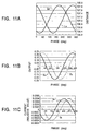
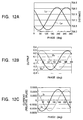
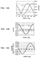
- FIGS. 9A, 10A, 11A, and 12A show the relationship between the distance L a between the neutral axis O and the output electrode a and the distance L b between the center axis O v and the output electrode b when the center axis O v is positioned at an arbitrary point in an ellipse or a circular trajectory.
- Figs. 9B, 10B, 11B, and 12B show each of voltage outputs V a and V b .
- Figs. 9C, 10C, 11C, and 12C show each of current outputs I a and I b .
- the elliptical trajectory of Fig. 9 has a great flatness, is more circular as in Figs. 10 and 11, and is completely circular in Fig. 12.
- the phase difference between the distance L a and the distance L b appears to be large with respect to an elliptical trajectory which is more flat than a linear vibration driving, with respect to a trajectory which is more circular than a flat elliptical trajectory, and with respect to a complete circular trajectory than an elliptical trajectory which is nearly circular.
- phase differences between the voltage outputs V a and V b and between the current outputs I a and I b are detected to be the greatest when the ratio the polarization coefficient (P xa , P xb ) in the X direction to the polarization coefficient (P ya , P yb ) in the Y direction is 1:1, and phase differences are detected to be small as this ratio deviates therefrom. This also coincides with the actually measured values.
- equation (3) shown in the above considerations may be said to be appropriate in order to visually recognize the waveforms of the current outputs I a and I b , even though the dimensions are different.
- each output electrode at a position far away from the center axis, it is possible to reliably detect a phase difference between the current outputs.
Landscapes
- Physics & Mathematics (AREA)
- General Physics & Mathematics (AREA)
- Engineering & Computer Science (AREA)
- Radar, Positioning & Navigation (AREA)
- Remote Sensing (AREA)
- Gyroscopes (AREA)
Abstract
Description
| Electrode position | Electrode position | Ellipse major axis | Ellipse minor axis | Polarization coefficient | Polarization coefficient | Polarization coefficient | Polarization coefficient | Remarks | |
| Lx | Ly | α | β | Kxa | Kya | Kxb | Kyb | ||
| First embodiment | 500 | 500 | 1 | 0 | 100 | 100 | -100 | -100 | Figs. 8A, 8B, and 8C |
| Second embodiment | 500 | 500 | 1 | 0.05 | 100 | 100 | -100 | -100 | Figs. 9A, 9B, and 9C |
| Third embodiment | 500 | 500 | 1 | 0.1 | 100 | 100 | -100 | -100 | Figs. 10A, 10B, and 10C |
| Fourth embodiment | 500 | 500 | 1 | 0.5 | 100 | 100 | -100 | -100 | Figs. 11A, 11B, and 11C |
| Fifth embodiment | 500 | 500 | 1 | 1 | 100 | 100 | -100 | -100 | Figs. 12A, 12B, and 12C |
| Sixth embodiment | 500 | 500 | 200 | 0 | 100 | 100 | -100 | -100 | Figs. 13A, 13B, and 13C |
| Seventh embodiment | 500 | 500 | 1 | 1 | 100 | 5 | -100 | -5 | Figs. 14A, 14B, and 14C |
Claims (6)
- A piezoelectric oscillator for outputting an angular velocity proportional to a Coriolis force in a rotating system, said piezoelectric oscillator comprising:a vibration leg having a rectangular or square cross section;a pair of driving electrodes extending with a spacing therebetween in a direction in which the vibration leg is driven and in the direction of the length of the vibration leg in the plane extending in said driving direction; anda pair of output electrodes opposing said driving electrodes, extending in the direction of the length of the vibration leg, on a surface opposite to the surface on which said driving electrodes of said vibration leg are formed, wherein when driving power is supplied to said driving electrodes, the vibration leg is driven to vibrate by a piezoelectric effect, and an angular velocity component proportional to said Coriolis force is obtained from said pair of output electrodes by a piezoelectric effect.
- A piezoelectric oscillator according to claim 1, wherein three-pronged vibration legs are provided in the oscillator, said driving electrode and said output electrode are provided in all the vibration legs, and a driving signal is provided between said driving electrode and said output electrode so that an angular velocity component proportional to a Coriolis force is detected from at least one set of output electrodes from among said output electrodes.
- A piezoelectric oscillator according to claim 2, wherein an output electrode other than said one set of output electrodes is fixed to an invariable potential.
- A piezoelectric oscillator according to claim 3, wherein said invariable potential is a ground potential.
- A piezoelectric oscillator according to claim 1,2,3 or 4 wherein when an axis which passes through the center of each vibration leg in the width direction and which extends in the direction of the length thereof is a center axis of each vibration leg, the output electrode is provided at a position farthest from the center axis in the plane of the vibration legs.
- A signal detection apparatus using a piezoelectric oscillator according to claim 1, said piezoelectric oscillator comprising: current-to-voltage conversion means for converting a current output obtained from said output electrodes into a voltage output, each of said output electrodes being grounded via an imaginary short-circuit in said current-to-voltage conversion means.
Applications Claiming Priority (2)
| Application Number | Priority Date | Filing Date | Title |
|---|---|---|---|
| JP12854599 | 1999-05-10 | ||
| JP11128545A JP2000321074A (en) | 1999-05-10 | 1999-05-10 | Piezoelectric oscillator and signal detector employing it |
Publications (2)
| Publication Number | Publication Date |
|---|---|
| EP1052479A2 true EP1052479A2 (en) | 2000-11-15 |
| EP1052479A3 EP1052479A3 (en) | 2003-08-13 |
Family
ID=14987414
Family Applications (1)
| Application Number | Title | Priority Date | Filing Date |
|---|---|---|---|
| EP00303646A Withdrawn EP1052479A3 (en) | 1999-05-10 | 2000-04-28 | Piezoelectric oscillator and signal detection apparatus using the same |
Country Status (4)
| Country | Link |
|---|---|
| US (1) | US6397676B1 (en) |
| EP (1) | EP1052479A3 (en) |
| JP (1) | JP2000321074A (en) |
| KR (1) | KR100368719B1 (en) |
Families Citing this family (1)
| Publication number | Priority date | Publication date | Assignee | Title |
|---|---|---|---|---|
| CN101173957B (en) * | 2006-10-30 | 2011-12-21 | 索尼株式会社 | Angular velocity sensor and electronic device |
Family Cites Families (4)
| Publication number | Priority date | Publication date | Assignee | Title |
|---|---|---|---|---|
| JPH0783671A (en) | 1993-07-22 | 1995-03-28 | Yoshiro Tomikawa | Vibration-type gyroscope |
| US5893054A (en) * | 1993-09-07 | 1999-04-06 | Boeing North American, Inc. | Amplitude detection and automatic gain control of a sparsely sampled sinusoid by computation including a hilbert transform |
| JPH09145378A (en) * | 1995-11-20 | 1997-06-06 | Alps Electric Co Ltd | Detector employing piezoelectric oscillator |
| JP3288597B2 (en) * | 1997-01-27 | 2002-06-04 | アルプス電気株式会社 | Vibratory gyroscope |
-
1999
- 1999-05-10 JP JP11128545A patent/JP2000321074A/en not_active Withdrawn
-
2000
- 2000-04-28 EP EP00303646A patent/EP1052479A3/en not_active Withdrawn
- 2000-05-09 KR KR10-2000-0024559A patent/KR100368719B1/en not_active Expired - Fee Related
- 2000-05-09 US US09/567,247 patent/US6397676B1/en not_active Expired - Fee Related
Also Published As
| Publication number | Publication date |
|---|---|
| EP1052479A3 (en) | 2003-08-13 |
| KR100368719B1 (en) | 2003-01-24 |
| US6397676B1 (en) | 2002-06-04 |
| JP2000321074A (en) | 2000-11-24 |
| KR20010014885A (en) | 2001-02-26 |
Similar Documents
| Publication | Publication Date | Title |
|---|---|---|
| KR100288070B1 (en) | Vibratory gyroscope | |
| US11835338B2 (en) | Sensor element, angular velocity sensor, and multi-axis angular velocity sensor | |
| CN109477717B (en) | Angular velocity sensor, sensor element, and multi-axis angular velocity sensor | |
| KR100397105B1 (en) | Drive detecting device for gyroscope | |
| US11112247B2 (en) | Angular velocity sensor, sensor element, and multi-axis angular velocity sensor | |
| CN1918452B (en) | Vibration gyroscope circuit, vibration gyroscope unit, and vibration gyroscope output detection method | |
| US6205857B1 (en) | Angular velocity sensing device | |
| US6397676B1 (en) | Piezoelectric oscillator and signal detection apparatus using the same | |
| KR100494967B1 (en) | Piezoelectric vibrating gyroscope utilizing an energy-trapping vibration mode | |
| JP3369033B2 (en) | Vibratory gyroscope | |
| US20200217663A1 (en) | Angular velocity sensor and sensor element | |
| KR960034990A (en) | Vibrating gyroscope | |
| US20210254976A1 (en) | Sensor element and angular velocity sensor | |
| US11656078B2 (en) | Sensor element and angular velocity sensor | |
| JPH07239339A (en) | Angular velocity sensor | |
| US20220042800A1 (en) | Sensor element and angular velocity sensor | |
| KR100215935B1 (en) | Vibrator of vibrating gyro | |
| JP2000283765A (en) | Tripod tuning fork vibrator and angular velocity sensor | |
| JP2000241167A (en) | Piezoelectric vibration gyro | |
| JP3766730B2 (en) | Energy-confined piezoelectric vibration gyroscope | |
| JPS61180107A (en) | Method for manufacturing angular velocity sensor element | |
| JPH11258286A (en) | Minute capacitance detection circuit | |
| JP2000249556A (en) | Triangular prism tripod tuning fork vibrator and angular velocity sensor | |
| JP2001082961A (en) | Angular velocity sensor and method of manufacturing angular velocity sensor | |
| JP2006105710A (en) | Piezoelectric vibration gyro |
Legal Events
| Date | Code | Title | Description |
|---|---|---|---|
| PUAI | Public reference made under article 153(3) epc to a published international application that has entered the european phase |
Free format text: ORIGINAL CODE: 0009012 |
|
| AK | Designated contracting states |
Kind code of ref document: A2 Designated state(s): AT BE CH CY DE DK ES FI FR GB GR IE IT LI LU MC NL PT SE |
|
| AX | Request for extension of the european patent |
Free format text: AL;LT;LV;MK;RO;SI |
|
| PUAL | Search report despatched |
Free format text: ORIGINAL CODE: 0009013 |
|
| AK | Designated contracting states |
Designated state(s): AT BE CH CY DE DK ES FI FR GB GR IE IT LI LU MC NL PT SE |
|
| AX | Request for extension of the european patent |
Extension state: AL LT LV MK RO SI |
|
| 17P | Request for examination filed |
Effective date: 20030922 |
|
| AKX | Designation fees paid |
Designated state(s): DE FR GB NL |
|
| 17Q | First examination report despatched |
Effective date: 20070313 |
|
| STAA | Information on the status of an ep patent application or granted ep patent |
Free format text: STATUS: THE APPLICATION IS DEEMED TO BE WITHDRAWN |
|
| 18D | Application deemed to be withdrawn |
Effective date: 20101119 |