EP1052404A2 - Hinge mechanism for variable displacement compressors - Google Patents
Hinge mechanism for variable displacement compressors Download PDFInfo
- Publication number
- EP1052404A2 EP1052404A2 EP00110002A EP00110002A EP1052404A2 EP 1052404 A2 EP1052404 A2 EP 1052404A2 EP 00110002 A EP00110002 A EP 00110002A EP 00110002 A EP00110002 A EP 00110002A EP 1052404 A2 EP1052404 A2 EP 1052404A2
- Authority
- EP
- European Patent Office
- Prior art keywords
- pin
- compressor
- axis
- plate
- guide
- Prior art date
- Legal status (The legal status is an assumption and is not a legal conclusion. Google has not performed a legal analysis and makes no representation as to the accuracy of the status listed.)
- Withdrawn
Links
- 238000006073 displacement reaction Methods 0.000 title claims abstract description 33
- 230000006835 compression Effects 0.000 description 8
- 238000007906 compression Methods 0.000 description 8
- 238000005452 bending Methods 0.000 description 6
- 230000007423 decrease Effects 0.000 description 6
- 230000000740 bleeding effect Effects 0.000 description 3
- 239000003507 refrigerant Substances 0.000 description 3
- 230000015572 biosynthetic process Effects 0.000 description 2
- 238000001816 cooling Methods 0.000 description 1
- 230000003247 decreasing effect Effects 0.000 description 1
- 238000004519 manufacturing process Methods 0.000 description 1
- 230000002093 peripheral effect Effects 0.000 description 1
- 238000004904 shortening Methods 0.000 description 1
Images

Classifications
-
- F—MECHANICAL ENGINEERING; LIGHTING; HEATING; WEAPONS; BLASTING
- F04—POSITIVE - DISPLACEMENT MACHINES FOR LIQUIDS; PUMPS FOR LIQUIDS OR ELASTIC FLUIDS
- F04B—POSITIVE-DISPLACEMENT MACHINES FOR LIQUIDS; PUMPS
- F04B27/00—Multi-cylinder pumps specially adapted for elastic fluids and characterised by number or arrangement of cylinders
- F04B27/08—Multi-cylinder pumps specially adapted for elastic fluids and characterised by number or arrangement of cylinders having cylinders coaxial with, or parallel or inclined to, main shaft axis
- F04B27/10—Multi-cylinder pumps specially adapted for elastic fluids and characterised by number or arrangement of cylinders having cylinders coaxial with, or parallel or inclined to, main shaft axis having stationary cylinders
- F04B27/1036—Component parts, details, e.g. sealings, lubrication
- F04B27/1054—Actuating elements
- F04B27/1072—Pivot mechanisms
Definitions
- the present invention relates to a hinge mechanism for variable displacement compressors used in, for example, automobile air-conditioners.
- a typical variable displacement compressor has a housing, which houses a crank chamber, and a cylinder block.
- a drive shaft extends through the crank chamber. Cylinder bores extending through the cylinder block accommodate pistons.
- a lug plate is fixed to the drive shaft to rotate integrally with the drive shaft.
- a swash plate which drives the pistons, is located adjacent to the lug plate.
- the lug plate is connected to the swash plate by a hinge mechanism. Each piston is coupled to the swash plate.
- the difference between the pressure of the crank chamber and the pressure of the cylinder bores is altered by adjusting the size of the opening in a displacement control valve.
- the inclination of the swash plate changes in accordance with the pressure difference, the displacement of the compressor varies accordingly.
- a hinge mechanism 51 which enables a swash plate 54 to incline, includes a guide bore 53 formed on a rear surface 52a of a lug plate 52 and a pin 55 projecting from a front surface of the swash plate 54.
- the guide bore 53 is formed so that its axis AXg is inclined relative to the rear surface of the lug plate 52.
- the pin 55 has a spherical end portion 55a, which is received by the guide bore 53 and which slides along the guide bore 53 in the direction of the guide bore axis AXg.
- Fa represents the force applied to the spherical portion 55a of the pin 55 by the compression load in a direction perpendicular to the pin axis AXp.
- Fb represents the force applied to the spherical portion 55a by the compression load in a direction perpendicular to the guide bore axis AXg.
- L represents the length of the pin 55 extending from the swash plate 54, and ⁇ represents the angle between the pin axis AXp and the guide bore axis AXg. The angle ⁇ is equivalent to the angle formed between the two forces Fa, Fb.
- the length L of the pin 55 must be relatively long so that the pin 55 can move in the guide bore 53 for a distance that enables the swash plate 54 to move between a maximum inclination position and a minimum inclination position. Further, the angle ⁇ between the pin axis AXp and the guide bore axis AXg must be minimized to avoid interference between the guide bore 53 and the pin 55. This results in a large force Fa being applied to the spherical portion 55a of the pin 55 by the compression load.
- the bending moment M applied to the proximal end 55b of the pin 55 is large. Therefore, the pin 55 must be securely fixed to the swash plate 54 by press-fitting the proximal end 55b of the pin 55 into a retaining bore 54a of the swash plate 54. Therefore, the dimensions of the proximal end 55b and the retaining bore 54a must be accurate. Further, the diameter and length of the press-fitted portion including the proximal end 55b must be as large as possible. This enlarges the pin 55 and its surrounding components. As a result, the manufacturing cost increases, and the weight of the compressor increases.
- Japanese Unexamined Patent Publication No. 10-54353 proposes a compressor in which the pin is located on the lug plate and received by a guide groove in the swash plate.
- the guide groove extends diagonally relative to the front surface of the swash plate.
- the pin slides in the axial direction of the guide groove, and the axes of the pin and guide groove intersect.
- the guide groove must be long to enable the pin to slide between locations corresponding to the swash plate's maximum inclination position (where the displacement of the compressor is maximal) and minimum inclination position (where the displacement of the compressor is minimal).
- a large support must be provided on the front surface of the swash plate to form the guide groove. This increases the weight of the swash plate.
- the large support may cause a weight imbalance of the swash plate. This would result in inaccurate positioning, or inclination, of the swash plate when the displacement control valve alters the pressure difference between the crank chamber and the cylinder bores.
- the pin extends from the rear surface of the lug plate toward a location on the swash plate corresponding to the top dead center position of the pistons.
- the angle of the pin relative to the drive shaft is always the same regardless of the compressor displacement.
- the bending moment at the proximal end of the pin increases as the compressor displacement increases.
- the present invention provides a variable displacement compressor having a crank chamber and a plurality of cylinder bores within a housing.
- a rotary drive shaft extends through the crank chamber and carries a lug plate integrally rotatable with the drive shaft.
- a drive plate is disposed adjacent to the lug plate and coupled to the lug plate by a hinge mechanism so as to be integrally rotatable with and inclinable in respect with the drive shaft.
- the displacement of the compressor varies according to an inclination of the drive plate based on a pressure difference between the crank chamber and each cylinder bore.
- the mechanism has at least one guide linearly extending in the lug plate and at least one pin projecting from the drive plate toward the lug plate and slidably contacting the guide. An axis of the pin extends in a direction intersecting an axis of the guide.
- variable displacement compressor according to the present invention will now be described with reference to Figs. 1 to 3.
- a front housing 11 is fastened to the front end of a cylinder block 12.
- a rear housing 13 is fastened to the rear end of the cylinder block 12.
- a valve plate 14 is arranged between the cylinder block 12 and the rear housing 13.
- a crank chamber 15 is defined in the front housing 11 and the cylinder block 12.
- a rotatable drive shaft 16 extends through the crank chamber 15 between the front housing 11 and the cylinder block 12.
- the drive shaft 16 is connected to an automobile engine (not shown) or other power source by an electromagnetic clutch. When the engine is running, the clutch connects the drive shaft 16 to the engine and rotates the drive shaft 16.
- a lug plate 19 is fixed to the drive shaft 16 in the crank chamber 15 to rotate integrally with the drive shaft 16.
- a drive plate which is a swash plate 20 in this embodiment, is fitted to the drive shaft 16 and supported so that it inclines while sliding in the direction of the drive shaft axis AXd.
- a hinge mechanism 21 is arranged between the lug plate 19 and the swash plate 20.
- the hinge mechanism 21 enables the swash plate 20 to rotate integrally with the drive shaft 16 and incline relative to the drive shaft 16.
- the inclination of the swash plate 20 with respect to a plane perpendicular to the drive shaft 16 decreases when the central portion of the swash plate 20 moves toward the cylinder block 12 and increases when the central portion moves toward the lug plate 19.
- Cylinder bores 12a extend through the cylinder block 12.
- a single-headed piston 22 is held in each cylinder bore 12a.
- the head 22a of each piston 22 is moved within the cylinder bore 12a, and a skirt 22b of each piston 22 is coupled to the peripheral portion of the swash plate 20 by shoes 23.
- the rotation of the swash plate 20 is converted into the reciprocation of the pistons 22 in the cylinder bores 12a.
- a suction chamber 24 and a discharge chamber 25 are defined in the rear housing 13.
- the valve plate 14 has a suction port 26, a suction valve 27 (flap valve), a discharge port 28, and a discharge valve 29 (flap valve) for each cylinder bore 12a.
- the crank chamber 15 and the suction chamber 24 are connected by a bleeding passage 30.
- the bleeding passage 30 is formed by an axial passage 30a extending along the axis of the drive shaft 16 and a communication aperture 30b extending through the cylinder block 12 and the valve plate 14.
- the discharge chamber 25 and the crank chamber 15 are connected by a pressurizing passage 31.
- the pressurizing passage 31 extends through the rear housing 13, the valve plate 14, and the cylinder block 12.
- a displacement control valve 32 is arranged in the pressurizing passage 31.
- the control valve 32 has a solenoid 32a and a valve body 32b, which is driven by the solenoid 32a to open and close the pressurizing passage 31.
- the solenoid 32a is excited and de-excited by a computer (not shown) in accordance with the cooling load, which depends primarily on the temperature of the passenger compartment.
- the valve body 32b adjusts the opening size of the pressurizing passage 31 to change the pressure of the crank chamber 15. This adjusts the difference between the pressure of the crank chamber 15, which acts on the front of the pistons 22, and the pressure of the cylinder bores 12a, which acts on the rear of the pistons 22.
- the pressure difference adjustment changes the inclination of the swash plate 20, which in turn, alters the stroke of the pistons 22 and varies the displacement of the compressor.
- valve body 32b opens the pressurizing passage 31 and connects the discharge chamber 25 to the crank chamber 15. This permits the high-pressure refrigerant gas in the discharge chamber 25 to flow into the crank chamber 15 through the pressurizing passage 31 and increases the pressure of the crank chamber 15.
- the increase of the crank chamber pressure increases the difference between the pressure applied to the pistons 22 by the crank chamber 15 and the pressure applied to the pistons 22 by the cylinder bores 12a. Consequently, the inclination of the swash plate 20 becomes minimal, as shown by the broken lines in Fig. 1, thus shortening the stroke of the pistons 22 and minimizing the displacement of the compressor.
- valve body 32b closes the pressurizing passage 31 and disconnects the discharge chamber 25 from the crank chamber 15. This causes the pressure of the crank chamber 15, due to the release of gas into the suction chamber 24 through the bleeding passage 30, to decrease.
- the decrease of the crank chamber pressure decreases the difference between the pressure applied to the pistons 22 by the crank chamber 15 and the pressure applied to the pistons 22 by the cylinder bores 12a. Consequently, the inclination of the swash plate 20 becomes maximal, as shown by the solid lines in Fig. 1, thus lengthening the stroke of the pistons 22 and maximizing the displacement of the compressor.
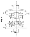
- each bracket 33 which are spaced equally apart from the drive shaft 16, project from the front surface 20a of the swash plate 20.
- the point corresponding to the top dead center position on the swash plate 20 is located between the brackets 33.
- Each bracket 33 has a retaining bore 33a into which a proximal portion 34b of a pin 34 is press-fitted.
- a spherical portion 34a is formed at the distal end of each pin 34.
- Two supports 35 project from the rear surface 19a of the lug plate 19 in association with the two pins 34.
- a guide 36 is defined on the distal end of each support 35.
- the guide 36 includes a bearing surface 36a, which has a generally semi-spherical cross-section, and a channel 36b, which receives the spherical portion 34a of the associated pin 34.
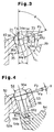
- the axis AXg of the guide 36 is parallel to a plane including the axis AXd of the drive shaft 16 and the point on the swash plate 20 corresponding to the upper dead center position. Further, the axis AXg of the guide 36 is inclined so that the axis AXg is farther from the rear surface 19a of the lug plate 19 at locations closer to the drive shaft 16.
- Each pin 34 engages the associated bearing surface 36a, and the axis AXp of each pin 34 is substantially perpendicular to the axis AXg of the associated guide 36.
- Each pin 34 engages the corresponding bearing surface 36a so that the spherical portion 34a slides in the direction of the axis AXg.
- the angle ⁇ between the axis AXp of each pin 34 and the axis AXg of the associated guide 36 is closest to a right angle. Further, the axis AXp of the pin 34 is substantially parallel to the axis AXd of the drive shaft 16.
- the pin 34 does not have to be extended in the direction of the axis AXg of the guide 36.
- the length L of the pin 34 can be relatively short.
- the axis AXp of the pin 34 and the axis AXg of the guide 36 are nearly perpendicular (within the range of 45 to 90 degrees) when the swash plate 20 is fully inclined.
- the angle ⁇ between the axis AXp of each pin 34 and the axis AXg of the associated guide 36 is large. This decreases the force Fa applied to the spherical portion 34a of the pin 34. Therefore, the bending moment M (obtained from equation (1)), which is applied to the proximal portion 34b of each pin 34 during operation of the compressor, is small even when a large compression load acts on the pin 34.
- the structure that fixes the proximal portion 34b of each pin 34 to the swash plate 20 is simplified. Further, the dimensions of the proximal portions 34b of the pins 34 and the retaining bores 33a of the brackets 33 do not have to be accurate. The formation of a bulky support on the front surface 20a of the swash plate 20 is also not necessary. In addition, the press-fitted portions, which include the proximal portions 34b of the pins 34, can be smaller. This allows the pins 34 and their surrounding parts to have smaller dimensions. As a result, the structure for fixing the pins 34 is inexpensive. Further, the weight of the swash plate 20 and the whole compressor are decreased.
- the guides 36 are located on the lug plate 19, the formation of a large support on the front surface 20a of the swash plate 20, as in the compressor of Japanese Unexamined Patent Publication No. 10-54353, is unnecessary. In this manner, an imbalance in the weight of the swash plate 20 is avoided. Therefore, the swash plate 20 is inclined accurately to the desired position when the difference between the pressure of the crank chamber 15 acting on the pistons 22 and the pressure of the cylinder bores 12a acting on the pistons 22 changes. Accordingly, the compressor responds quickly to displacement control.
- each pin 34 When the inclination of the swash plate 20 and the displacement are maximal, the axis AXp of each pin 34 is substantially parallel to the axis AXd of the drive shaft 16. Accordingly, when the displacement is maximal and the compression load acting on the pins 34 is maximal, the pin axes AXp are substantially parallel to the drive shaft axis AXd. In this state, the compression load acts in a direction coinciding with the axes AXp of the pins 34. This decreases the bending moment M applied to the proximal portions 34b of the pin 34 by the large compression loads produced when the compressor is operating in a maximum displacement state.
- the illustrated embodiment may be modified by providing the lug plate 19 only one of the guides 36 and the swash plate 20 with only one of the pins 34.
- the present invention may be applied to a compressor employing a wobble plate in lieu of the swash plate.
- An improved variable displacement compressor has a drive shaft (16) extending through a crank chamber.
- a lug plate (19) is integrally fixed to the drive shaft (16).
- a drive plate (20) is connected to and driven by the lug plate (19) by a hinge mechanism (21).
- the drive plate (20) inclines with respect to the drive shaft (16) to vary the displacement of the compressor.
- the hinge mechanism (21) has a linear guide (19) on the lug plate (19) and a pin (34) projecting from the drive plate (20) toward the lug plate (19).
- a bearing surface (36a) engages the pin (34).
- the pin (34) has an axis (AXp) that intersects an axis (Axg) of the guide (19).
- the axis (AXp) of the pin (34) is parallel to the axis (AXd) of the drive shaft (20) when the compressor operates with a maximum load.
Landscapes
- Engineering & Computer Science (AREA)
- Mechanical Engineering (AREA)
- General Engineering & Computer Science (AREA)
- Compressors, Vaccum Pumps And Other Relevant Systems (AREA)
Abstract
Description
Claims (8)
- A variable displacement compressor having a crank chamber (15) and a plurality of cylinder bores (12a) within a housing (11, 12, 13), wherein a rotary drive shaft (16) extends through the crank chamber and carries a lug plate (19) integrally rotatable with the drive shaft (16), wherein a drive plate (20) is disposed adjacent to the lug plate (19) and coupled to the lug plate (19) by a hinge mechanism (21) so as to be integrally rotatable with and inclinable in respect with the drive shaft (16), and wherein the displacement of the compressor varies according to an inclination of the drive plate (20) based on a pressure difference between the crank chamber (15) and each cylinder bore (12a), characterized in that said mechanism (21) has at least one guide (19) linearly extending in the lug plate (19) and at least one pin (34) projecting from the drive plate (20) toward the lug plate (19) and slidably contacting the guide (19), wherein an axis (Axg) of the pin (34) nearly perpendicularly extends to an axis (Axp) of the guide (19).the axis of the guide extends in a direction intersecting the axis of the pin
- The compressor as set forth in Claim 1, characterized in that said guide (36) includes a channel (36b) for clamping the pin (34), wherein said channel (36b) has an inner supporting surface and wherein said pin (34) slidably engages the inner supporting surface.
- The compressor as set forth in Claims 1 or 2, characterized in that at least one bracket (33) provided on the drive plate (20), said bracket (33) including a bore (33a), wherein said pin (34) has a proximal end (34a) press-fitted within the bore (33a).
- The compressor as set forth in any one of the preceding claims, characterized in that said axis (Axp) of the pin (34) extends substantially parallelly with the axis of the drive shaft (16) when the compressor is driven at its maximum displacement.
- The compressor as set forth in any one of the preceding claims, characterized by a plurality of pistons (22), each coupled to the drive plate (20) and movable in the associated cylinder bore (12a) by a stroke based on the inclination of the drive plate (20), wherein said piston (22) has a first end surface directed to the crank chamber (15) and a second end surface directed to the cylinder bore (12a), and wherein the inclination of the drive plate (20) is subject to a difference between pressures respectively acting on the first end surface and the second end surface.
- The compressor as set forth in any one of the preceding claims, characterized by that said pin (34) has a spherical portion (34a) at its distal end.
- The compressor as set forth in any one the preceding claims, characterized in that said drive plate includes a swash plate (20).
- The compressor as set forth in any one of the preceding claims, characterized in that the axis (AXg) of the guide (36) extends nearly perpendicular to the axis (AXp) of the pin (34) within a range of 45° to 90°.
Applications Claiming Priority (2)
| Application Number | Priority Date | Filing Date | Title |
|---|---|---|---|
| JP11132646A JP2000320454A (en) | 1999-05-13 | 1999-05-13 | Variable displacement compressor |
| JP13264699 | 1999-05-13 |
Publications (2)
| Publication Number | Publication Date |
|---|---|
| EP1052404A2 true EP1052404A2 (en) | 2000-11-15 |
| EP1052404A3 EP1052404A3 (en) | 2001-03-21 |
Family
ID=15086203
Family Applications (1)
| Application Number | Title | Priority Date | Filing Date |
|---|---|---|---|
| EP00110002A Withdrawn EP1052404A3 (en) | 1999-05-13 | 2000-05-11 | Hinge mechanism for variable displacement compressors |
Country Status (3)
| Country | Link |
|---|---|
| US (1) | US6474955B1 (en) |
| EP (1) | EP1052404A3 (en) |
| JP (1) | JP2000320454A (en) |
Cited By (2)
| Publication number | Priority date | Publication date | Assignee | Title |
|---|---|---|---|---|
| US6860188B2 (en) | 2003-06-20 | 2005-03-01 | Visteon Global Technologies, Inc. | Variable displacement compressor hinge mechanism |
| US9765764B2 (en) | 2014-04-07 | 2017-09-19 | Hanon Systems | Hinge mechanism for a variable displacement compressor |
Families Citing this family (6)
| Publication number | Priority date | Publication date | Assignee | Title |
|---|---|---|---|---|
| JP2004068757A (en) * | 2002-08-08 | 2004-03-04 | Toyota Industries Corp | Variable displacement compressor |
| JP2006242120A (en) * | 2005-03-04 | 2006-09-14 | Toyota Industries Corp | Variable displacement type swash plate compressor |
| US20080302236A1 (en) * | 2005-03-09 | 2008-12-11 | Calsonic Kansei Corporation | Variable Displacement Compressor |
| US7444921B2 (en) | 2006-08-01 | 2008-11-04 | Visteon Global Technologies, Inc. | Swash ring compressor |
| JP4924464B2 (en) * | 2008-02-05 | 2012-04-25 | 株式会社豊田自動織機 | Swash plate compressor |
| JP2009203888A (en) * | 2008-02-28 | 2009-09-10 | Toyota Industries Corp | Variable displacement type swash plate compressor |
Citations (1)
| Publication number | Priority date | Publication date | Assignee | Title |
|---|---|---|---|---|
| JPH1054353A (en) | 1996-08-09 | 1998-02-24 | Zexel Corp | Variable displacement compressor |
Family Cites Families (18)
| Publication number | Priority date | Publication date | Assignee | Title |
|---|---|---|---|---|
| JP2846089B2 (en) | 1990-09-14 | 1999-01-13 | 株式会社日立製作所 | Variable displacement compressor |
| JP3125952B2 (en) | 1993-04-08 | 2001-01-22 | 株式会社豊田自動織機製作所 | Variable capacity swash plate compressor |
| JPH08338362A (en) * | 1995-06-08 | 1996-12-24 | Toyota Autom Loom Works Ltd | Variable displacement type swash plate type compressor |
| DE59506900D1 (en) | 1995-07-28 | 1999-10-28 | Keiper Gmbh & Co | Vehicle seat |
| JP3422186B2 (en) * | 1995-11-24 | 2003-06-30 | 株式会社豊田自動織機 | Variable capacity compressor |
| US6112639A (en) * | 1995-12-18 | 2000-09-05 | Kabushiki Kaisha Toyoda Jidoshokki Seisakusho | Structure for collecting leaking oil in compressor |
| JPH09250452A (en) * | 1996-03-19 | 1997-09-22 | Toyota Autom Loom Works Ltd | Lubricating structure in compressor |
| JP3787903B2 (en) * | 1996-08-05 | 2006-06-21 | 株式会社豊田自動織機 | Variable capacity compressor |
| JPH10131850A (en) * | 1996-10-25 | 1998-05-19 | Toyota Autom Loom Works Ltd | Compressor |
| JPH10169557A (en) * | 1996-12-06 | 1998-06-23 | Toyota Autom Loom Works Ltd | Compressor |
| JPH10266952A (en) | 1997-03-25 | 1998-10-06 | Zexel Corp | Variable displacement type swash plate compressor |
| JP3832012B2 (en) * | 1997-03-31 | 2006-10-11 | 株式会社豊田自動織機 | Variable capacity compressor |
| JPH1193833A (en) * | 1997-09-17 | 1999-04-06 | Toyota Autom Loom Works Ltd | Variable displacement swash plate type compressor |
| JPH11159458A (en) * | 1997-11-27 | 1999-06-15 | Toyota Autom Loom Works Ltd | Cooling structure of compressor |
| JPH11173341A (en) * | 1997-12-11 | 1999-06-29 | Toyota Autom Loom Works Ltd | Power transmission mechanism |
| JPH11343969A (en) * | 1998-03-31 | 1999-12-14 | Toyota Autom Loom Works Ltd | Variable displacement compressor |
| JPH11287181A (en) * | 1998-04-02 | 1999-10-19 | Toyota Autom Loom Works Ltd | Variable displacement compressor |
| JP2001289159A (en) | 2000-04-03 | 2001-10-19 | Zexel Valeo Climate Control Corp | Variable displacement swash plate compressor |
-
1999
- 1999-05-13 JP JP11132646A patent/JP2000320454A/en active Pending
-
2000
- 2000-05-10 US US09/568,363 patent/US6474955B1/en not_active Expired - Fee Related
- 2000-05-11 EP EP00110002A patent/EP1052404A3/en not_active Withdrawn
Patent Citations (1)
| Publication number | Priority date | Publication date | Assignee | Title |
|---|---|---|---|---|
| JPH1054353A (en) | 1996-08-09 | 1998-02-24 | Zexel Corp | Variable displacement compressor |
Cited By (3)
| Publication number | Priority date | Publication date | Assignee | Title |
|---|---|---|---|---|
| US6860188B2 (en) | 2003-06-20 | 2005-03-01 | Visteon Global Technologies, Inc. | Variable displacement compressor hinge mechanism |
| US7021193B2 (en) | 2003-06-20 | 2006-04-04 | Visteon Global Technologies, Inc. | Variable displacement compressor hinge mechanism |
| US9765764B2 (en) | 2014-04-07 | 2017-09-19 | Hanon Systems | Hinge mechanism for a variable displacement compressor |
Also Published As
| Publication number | Publication date |
|---|---|
| JP2000320454A (en) | 2000-11-21 |
| EP1052404A3 (en) | 2001-03-21 |
| US6474955B1 (en) | 2002-11-05 |
Similar Documents
| Publication | Publication Date | Title |
|---|---|---|
| US5890876A (en) | Control valve in variable displacement compressor | |
| US5259736A (en) | Swash plate type compressor with swash plate hinge coupling mechanism | |
| US6010312A (en) | Control valve unit with independently operable valve mechanisms for variable displacement compressor | |
| US5964578A (en) | Control valve in variable displacement compressor | |
| JP3422186B2 (en) | Variable capacity compressor | |
| US5615599A (en) | Guiding mechanism for reciprocating piston of piston-type compressor | |
| EP0748937A2 (en) | Displacement controlling structure for clutchless variable displacement compressor | |
| KR100302820B1 (en) | Control Valve and Mounting Method for Variable Capacity Compressor | |
| US5931079A (en) | Variable capacity swash plate compressor | |
| US6116145A (en) | Variable displacement compressor | |
| US6010313A (en) | Single-headed piston type compressor | |
| US6146107A (en) | Variable displacement compressor | |
| US6077047A (en) | Variable displacement compressor | |
| KR20050086356A (en) | Variable volume type compressor | |
| US6474955B1 (en) | Hinge mechanism for variable displacement compressors | |
| US6076449A (en) | Variable displacement compressor | |
| US6123513A (en) | Compressor with improved piston for lubricating the coupling portion between the piston and the driving body | |
| US20160047367A1 (en) | Variable displacement swash-plate compressor | |
| US6544004B2 (en) | Single-headed piston type compressor | |
| US6048178A (en) | Compressor | |
| CA2221475C (en) | Variable displacement compressor | |
| US6546841B2 (en) | Swash plate compressor and piston therefor | |
| US20040055456A1 (en) | Variable displacement compressor | |
| US5882179A (en) | Compressor with bearing between the drive shaft and the swash-plate boss | |
| US6260469B1 (en) | Piston for use in a compressor |
Legal Events
| Date | Code | Title | Description |
|---|---|---|---|
| PUAI | Public reference made under article 153(3) epc to a published international application that has entered the european phase |
Free format text: ORIGINAL CODE: 0009012 |
|
| 17P | Request for examination filed |
Effective date: 20000511 |
|
| AK | Designated contracting states |
Kind code of ref document: A2 Designated state(s): DE FR IT |
|
| AX | Request for extension of the european patent |
Free format text: AL;LT;LV;MK;RO;SI |
|
| PUAL | Search report despatched |
Free format text: ORIGINAL CODE: 0009013 |
|
| AK | Designated contracting states |
Kind code of ref document: A3 Designated state(s): AT BE CH CY DE DK ES FI FR GB GR IE IT LI LU MC NL PT SE |
|
| AX | Request for extension of the european patent |
Free format text: AL;LT;LV;MK;RO;SI |
|
| AKX | Designation fees paid |
Free format text: DE FR IT |
|
| RAP1 | Party data changed (applicant data changed or rights of an application transferred) |
Owner name: KABUSHIKI KAISHA TOYOTA JIDOSHOKKI |
|
| 17Q | First examination report despatched |
Effective date: 20050427 |
|
| STAA | Information on the status of an ep patent application or granted ep patent |
Free format text: STATUS: THE APPLICATION IS DEEMED TO BE WITHDRAWN |
|
| 18D | Application deemed to be withdrawn |
Effective date: 20050908 |