EP1052375A2 - Apparatus and method for relieving thermally induced stresses in inner and outer bands of thermally cooled turbine nozzle stages - Google Patents
Apparatus and method for relieving thermally induced stresses in inner and outer bands of thermally cooled turbine nozzle stages Download PDFInfo
- Publication number
- EP1052375A2 EP1052375A2 EP00304037A EP00304037A EP1052375A2 EP 1052375 A2 EP1052375 A2 EP 1052375A2 EP 00304037 A EP00304037 A EP 00304037A EP 00304037 A EP00304037 A EP 00304037A EP 1052375 A2 EP1052375 A2 EP 1052375A2
- Authority
- EP
- European Patent Office
- Prior art keywords
- cover
- combustion
- wall
- hot gases
- flowing
- Prior art date
- Legal status (The legal status is an assumption and is not a legal conclusion. Google has not performed a legal analysis and makes no representation as to the accuracy of the status listed.)
- Granted
Links
Images


Classifications
-
- F—MECHANICAL ENGINEERING; LIGHTING; HEATING; WEAPONS; BLASTING
- F02—COMBUSTION ENGINES; HOT-GAS OR COMBUSTION-PRODUCT ENGINE PLANTS
- F02C—GAS-TURBINE PLANTS; AIR INTAKES FOR JET-PROPULSION PLANTS; CONTROLLING FUEL SUPPLY IN AIR-BREATHING JET-PROPULSION PLANTS
- F02C9/00—Controlling gas-turbine plants; Controlling fuel supply in air- breathing jet-propulsion plants
- F02C9/26—Control of fuel supply
- F02C9/28—Regulating systems responsive to plant or ambient parameters, e.g. temperature, pressure, rotor speed
-
- F—MECHANICAL ENGINEERING; LIGHTING; HEATING; WEAPONS; BLASTING
- F01—MACHINES OR ENGINES IN GENERAL; ENGINE PLANTS IN GENERAL; STEAM ENGINES
- F01D—NON-POSITIVE DISPLACEMENT MACHINES OR ENGINES, e.g. STEAM TURBINES
- F01D25/00—Component parts, details, or accessories, not provided for in, or of interest apart from, other groups
- F01D25/08—Cooling; Heating; Heat-insulation
- F01D25/10—Heating, e.g. warming-up before starting
-
- F—MECHANICAL ENGINEERING; LIGHTING; HEATING; WEAPONS; BLASTING
- F01—MACHINES OR ENGINES IN GENERAL; ENGINE PLANTS IN GENERAL; STEAM ENGINES
- F01D—NON-POSITIVE DISPLACEMENT MACHINES OR ENGINES, e.g. STEAM TURBINES
- F01D11/00—Preventing or minimising internal leakage of working-fluid, e.g. between stages
- F01D11/08—Preventing or minimising internal leakage of working-fluid, e.g. between stages for sealing space between rotor blade tips and stator
- F01D11/14—Adjusting or regulating tip-clearance, i.e. distance between rotor-blade tips and stator casing
- F01D11/20—Actively adjusting tip-clearance
- F01D11/24—Actively adjusting tip-clearance by selectively cooling-heating stator or rotor components
-
- F—MECHANICAL ENGINEERING; LIGHTING; HEATING; WEAPONS; BLASTING
- F01—MACHINES OR ENGINES IN GENERAL; ENGINE PLANTS IN GENERAL; STEAM ENGINES
- F01D—NON-POSITIVE DISPLACEMENT MACHINES OR ENGINES, e.g. STEAM TURBINES
- F01D25/00—Component parts, details, or accessories, not provided for in, or of interest apart from, other groups
- F01D25/08—Cooling; Heating; Heat-insulation
-
- F—MECHANICAL ENGINEERING; LIGHTING; HEATING; WEAPONS; BLASTING
- F01—MACHINES OR ENGINES IN GENERAL; ENGINE PLANTS IN GENERAL; STEAM ENGINES
- F01D—NON-POSITIVE DISPLACEMENT MACHINES OR ENGINES, e.g. STEAM TURBINES
- F01D25/00—Component parts, details, or accessories, not provided for in, or of interest apart from, other groups
- F01D25/08—Cooling; Heating; Heat-insulation
- F01D25/12—Cooling
-
- F—MECHANICAL ENGINEERING; LIGHTING; HEATING; WEAPONS; BLASTING
- F01—MACHINES OR ENGINES IN GENERAL; ENGINE PLANTS IN GENERAL; STEAM ENGINES
- F01D—NON-POSITIVE DISPLACEMENT MACHINES OR ENGINES, e.g. STEAM TURBINES
- F01D5/00—Blades; Blade-carrying members; Heating, heat-insulating, cooling or antivibration means on the blades or the members
- F01D5/12—Blades
- F01D5/14—Form or construction
- F01D5/18—Hollow blades, i.e. blades with cooling or heating channels or cavities; Heating, heat-insulating or cooling means on blades
- F01D5/187—Convection cooling
-
- F—MECHANICAL ENGINEERING; LIGHTING; HEATING; WEAPONS; BLASTING
- F01—MACHINES OR ENGINES IN GENERAL; ENGINE PLANTS IN GENERAL; STEAM ENGINES
- F01D—NON-POSITIVE DISPLACEMENT MACHINES OR ENGINES, e.g. STEAM TURBINES
- F01D9/00—Stators
- F01D9/02—Nozzles; Nozzle boxes; Stator blades; Guide conduits, e.g. individual nozzles
-
- F—MECHANICAL ENGINEERING; LIGHTING; HEATING; WEAPONS; BLASTING
- F02—COMBUSTION ENGINES; HOT-GAS OR COMBUSTION-PRODUCT ENGINE PLANTS
- F02C—GAS-TURBINE PLANTS; AIR INTAKES FOR JET-PROPULSION PLANTS; CONTROLLING FUEL SUPPLY IN AIR-BREATHING JET-PROPULSION PLANTS
- F02C7/00—Features, components parts, details or accessories, not provided for in, or of interest apart form groups F02C1/00 - F02C6/00; Air intakes for jet-propulsion plants
- F02C7/20—Mounting or supporting of plant; Accommodating heat expansion or creep
-
- F—MECHANICAL ENGINEERING; LIGHTING; HEATING; WEAPONS; BLASTING
- F05—INDEXING SCHEMES RELATING TO ENGINES OR PUMPS IN VARIOUS SUBCLASSES OF CLASSES F01-F04
- F05D—INDEXING SCHEME FOR ASPECTS RELATING TO NON-POSITIVE-DISPLACEMENT MACHINES OR ENGINES, GAS-TURBINES OR JET-PROPULSION PLANTS
- F05D2240/00—Components
- F05D2240/80—Platforms for stationary or moving blades
- F05D2240/81—Cooled platforms
Definitions
- the present invention relates generally to gas turbines having closed cooling circuits in one or more nozzle stages and particularly relates to reducing thermally induced stresses in the inner and outer bands of the nozzle stages caused by temperature differentials between the hot gases of combustion flowing along the hot gas path and the cooling medium.
- one or more of the nozzle stages are cooled by passing a cooling medium from a plenum in each nozzle segment portion forming part of the outer band through one or more nozzle vanes to cool the nozzles and into a plenum in the corresponding inner band portion.
- the cooling medium then flows radially outwardly from the inner band portion, again through the one or more nozzle vanes for discharge.
- the cooling medium is steam.
- Each of the nozzle segments including the inner and outer band portions and one or more nozzle vanes are typically cast. Covers are applied to the inner and outer band portions on sides thereof remote from the hot gas path to define plenums for receiving the cooling medium. The covers are not cast with the nozzle segments.
- the hot gas flowpath sides of the bands are exposed to relatively high temperatures, while the covers which are not directly exposed to the hot gases of combustion, along the flowpath, remain considerably cooler. Additionally, the covers are exposed externally to compressor discharge air which, while having a temperature higher than the temperature of the steam cooling medium is still considerably less than the temperature of the inner and outer bands exposed to the hot gases of combustion.
- the temperature differential between the covers and the band portions, particularly along the weld lines between the covers and walls of the band portions exposed to the hot gas path cover results in high thermal stresses.
- the temperature difference between the flowpath exposed surfaces of the inner and outer bands and the covers exposed both to the cooling medium and the compressor discharge air is reduced by flowing a thermal medium along the covers at a temperature intermediate the temperature of the hot gases of combustion and the cooling medium through the cover and particularly adjacent the joints between the covers and the nozzle bands.
- the thermal medium flowing along the covers is at a significantly higher temperature than the temperatures of the cooling medium and the compressor discharge air in order to heat the cover so that the cover temperature approaches the bulk temperature of the flowpath exposed surfaces of the nozzle bands.
- a portion of the combustion path gases are directed through entry ports at the leading edges of the cover.
- the mixture of hot combustion gases and compressor discharge air is (i) lower in pressure than both the compressor discharge air and hot gases of combustion at the leading edge of the passages and (ii) higher than the pressure of the hot gases of combustion at the trailing edge of the cover.
- the cooling medium flows passively through the passages between the leading edges to the trailing edges of the nozzle segments.
- apparatus for controlling a temperature mismatch in at least one of the inner and outer bands of turbine nozzles having cooling circuits for flowing a cooling medium comprising a nozzle segment having at least one nozzle vane and inner and outer nozzle band portions adjacent opposite ends of the nozzle vane and in part defining a path for flowing hot gases of combustion, one of the band portions forming a wall exposed to the hot gas path of the turbine and having a cover on a side of the wall remote from the hot gas path, the cover and the wall defining a plenum therebetween for receiving the cooling medium forming part of the cooling circuit, the segment including at least one passage through the cover for flowing a thermal medium at a temperature intermediate the temperature of the cooling medium and the hot gases of combustion to reduce the temperature differential between the cover and the wall and thereby reduce thermal-induced stresses in the one band portion.
- apparatus for controlling a temperature mismatch in at least one of inner and outer bands having a turbine nozzle vane therebetween and a cooling circuit for flowing a cooling medium through the nozzle vane comprising a nozzle segment having at least one nozzle vane and inner and outer nozzle band portions adjacent opposite ends of the nozzle vane and in part defining a path for flowing hot gases of combustion, one of the band portions forming a wall exposed to a hot gas path of the turbine and having a cover on a side of the wall remote from the hot gas path, the cover and the wall, defining a plenum therebetween for receiving the cooling medium forming part of a nozzle cooling circuit, the cover and the wall of the band forming joints therebetween and along opposite sides thereof, the segment including passages through the cover from adjacent a leading edge to a trailing edge thereof and adjacent the joints for flowing the medium at a temperature intermediate the temperature of the cooling medium and the hot gases of combustion to reduce the temperature differential between the cover and the wail in
- a method of reducing a temperature differential between a wall of an inner or an outer band of a turbine nozzle segment having a vane between the walls and a cover on a side of the wall remote from a flowpath for hot gases of combustion past the nozzle wherein the wall and cover define a plenum therebetween for receiving a cooling medium for flow through the nozzle vane comprising the steps of flowing a thermal medium through at least one passage in the cover at a temperature intermediate respective temperatures of the hot gases of combustion and the cooling medium to elevate the temperature of the cover.
- a nozzle stage generally designated 10, comprised of a plurality of nozzle segments arranged circumferentially about the axis of the turbine.
- Each of the nozzle segments 12 includes one or more nozzle vanes 14 disposed between inner and outer band portions 16 and 18, respectively. It will be appreciated that the inner and outer band portions 16 and 18 and nozzle vanes 14 define a flowpath for hot gases of combustion flowing in the direction of the arrow 20.
- the nozzle segments are circumferentially arrayed about the turbine axis and secured to a fixed shell 22.
- Additionally illustrated in Figure 1 is one of a plurality of circumferentially spaced buckets 24 forming part of the rotor of the turbine, it being appreciated that the hot gases of combustion flow through the buckets and rotate the rotor.
- the inner and outer band portions 24 and 26, respectively, are comprised of inner and outer walls 25 and 27, respectively, exposed to the hot gases of combustion in flowpath 20 and inner and outer covers 28 and 30.
- the covers define with the walls plenums P for receiving a cooling medium, one plenum P being illustrated in Figure 2 by the dashed lines.
- the cooling medium is supplied to the outer wall plenum for impingement cooling of the radial outer band portion and for flow through the vane 14 into a plenum in the inner band portion.
- the cooling medium flows into the latter plenum for impingement cooling of the inner band wall and for discharge through radially outwardly extending passages through the vane 14 for return.
- the nozzle segment may be cast for example, from a nickel alloy material.
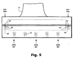
- the covers 28 and 30 are secured to the walls of the cast nozzle segments to define the plenums, preferably by welded or brazed joints 32, illustrated in Figure 5.
- the walls of the inner and outer band portions are, of course, exposed to the high temperature of the hot gases of combustion flowing along the flowpath 20, while the covers 28 are exposed to compressor discharge air on sides thereof remote from the walls.
- the compressor discharge air is, of course, at a lower temperature than the hot gases of combustion.
- the cooling medium supplied to the nozzle via the plenums is at a temperature intermediate the temperature of the compressor discharge air and the hot gases flowing along flowpath 20. As noted previously, this causes a thermal mismatch between the cover and the inner and outer band portions, causing thermal stresses in the inner and outer band segments.
- the present invention minimizes or eliminates those thermal stresses by elevating the temperature of the cover to a temperature closer to the temperature of the inner and outer walls and intermediate the bulk temperature of the walls and the temperature of the cooling medium.
- each cover has at least one passage and preferably a pair of passages 42 extending from its leading edge to its trailing edge for flowing a thermal, i.e., a heating medium to heat the cover and raise its temperature to approximate the bulk temperature of the wall.
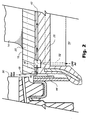
- the cover 26 includes at least one entry port 40 to each passage 42 which extends between the leading and trailing edges 44 and 46, respectively, of the cover to an exit port 47.
- a mixing chamber 48 is disposed in each passage 42 adjacent the leading edge 44.
- a slot 49 is formed between the leading edge of the nozzle segment and the adjoining structure 50 to permit passage of hot gases flowing along the hot gas path to enter the entry port 40 of the passage 42.
- a passage 52 extends through the cover and lies in communication at respective opposite ends with the mixing chamber 48 and an area 54 containing compressor discharge air. Consequently, both hot gases of combustion and compressor discharge air are supplied to the mixing chamber 48 and mixed to provide a thermal medium having a temperature sufficient to raise the temperature of the cover to approximate the bulk temperature of the wall.
- an entry port 40 and passage 42 are located directly adjacent each joint between the cover and the wall along opposite sides of the cover. Additional passages 42, entry ports 40, mixing chambers 48 and exit ports 47 may also be provided through the covers from their leading edges to their trailing edges between the opposite sides of the covers. These additional passages therefore similarly heat the cover between opposite sides thereof, with the mixture of hot combustion gases and compressor discharge air.
- FIGs 3 and 4 there is schematically illustrated a pair of covers which are useful with either the inner or outer band portions.
- the inner cover 28 includes the passages 42 adjacent opposite side edges, the outline of the vane 14 being superimposed by the dashed lines on the illustrated cover.
- each passage 42 is angled at substantially the same angle as the hot gases of combustion flow from the trailing edge of the vane. It will be appreciated that the passages 42 illustrated in Figure 3 lie along opposite sides of the cover directly adjacent the joints between the covers and the band portion 16.
- the entirety of the cover is heated by the mixed hot gases of combustion and compressor discharge air.
- a serpentine passage 60 is provided through the cover.
- the entry port 62 directs hot gases of combustion into the mixing chamber 64.
- the combined hot gases and compressor discharge air then flow along passage 60 and into the hot gas stream via exit port 66.
- the exit port 66 is angled at substantially the same angle as the angle of the trailing edge of the vane so that the exiting thermal medium flows in substantially the same direction as the hot gases of combustion leaving the trailing edge of the vane.
- the radial outer band portion is similarly configured as the inner band portion just described. That is, the outer band portion similarly includes entry ports adjacent opposite sides of the outer band portion in communication with mixing chambers adjacent the leading edge for mixing compressor discharge air and hot gases of combustion for flow through passages along the opposite edges of the cover and into the hot gas path adjacent the trailing edge of the outer cover.
- the temperature of the covers is heated by the mixture of the hot gases of combustion and compressor discharge air to a temperature which heats the covers to approximate the bulk temperature of the wall of the inner or outer band portions. Consequently, the temperature differential between the covers and the inner and outer wall band portions is substantially reduced sufficiently to minimize or eliminate thermal stresses.
- a substantial number of passages may be disposed through each of the covers, substantially paralleling the pair of passages along opposite sides of the covers. For example, as illustrated in Figure 5, the entry apertures for flowing hot gases of combustion into a plurality of mixing chambers within the cover and mixing the hot gases of combustion with compressor discharge air via passages 70 is illustrated. Thus, the entirety of the cover can be heated. Also, the pressure of the hot gases of combustion and compressor discharge air at the leading edge is greater than the pressure of the flowpath at the trailing edge. In this manner, the flow of the mixed gases does not require pumping and the gases flow passively to heat the covers.
Landscapes
- Engineering & Computer Science (AREA)
- Mechanical Engineering (AREA)
- General Engineering & Computer Science (AREA)
- Chemical & Material Sciences (AREA)
- Combustion & Propulsion (AREA)
- Turbine Rotor Nozzle Sealing (AREA)
Abstract
Description
- The present invention relates generally to gas turbines having closed cooling circuits in one or more nozzle stages and particularly relates to reducing thermally induced stresses in the inner and outer bands of the nozzle stages caused by temperature differentials between the hot gases of combustion flowing along the hot gas path and the cooling medium.
- In industrial or land-based gas turbines, one or more of the nozzle stages are cooled by passing a cooling medium from a plenum in each nozzle segment portion forming part of the outer band through one or more nozzle vanes to cool the nozzles and into a plenum in the corresponding inner band portion. The cooling medium then flows radially outwardly from the inner band portion, again through the one or more nozzle vanes for discharge. Typically, the cooling medium is steam. Each of the nozzle segments including the inner and outer band portions and one or more nozzle vanes are typically cast. Covers are applied to the inner and outer band portions on sides thereof remote from the hot gas path to define plenums for receiving the cooling medium. The covers are not cast with the nozzle segments. Rather, they are preferably later applied to the inner and outer band portions, for example, by welding or brazing. With this arrangement the hot gas flowpath sides of the bands are exposed to relatively high temperatures, while the covers which are not directly exposed to the hot gases of combustion, along the flowpath, remain considerably cooler. Additionally, the covers are exposed externally to compressor discharge air which, while having a temperature higher than the temperature of the steam cooling medium is still considerably less than the temperature of the inner and outer bands exposed to the hot gases of combustion. The temperature differential between the covers and the band portions, particularly along the weld lines between the covers and walls of the band portions exposed to the hot gas path cover results in high thermal stresses. As a consequence, there is a need to reduce the thermally induced stresses along the inner and outer bands of the nozzle stages caused principally by temperature differentials between the hot gases of combustion in the hot gas path, the cooling medium flowing through the inner and outer bands and the compressor discharge air.
- In accordance with a preferred embodiment of the present invention, the temperature difference between the flowpath exposed surfaces of the inner and outer bands and the covers exposed both to the cooling medium and the compressor discharge air is reduced by flowing a thermal medium along the covers at a temperature intermediate the temperature of the hot gases of combustion and the cooling medium through the cover and particularly adjacent the joints between the covers and the nozzle bands. The thermal medium flowing along the covers is at a significantly higher temperature than the temperatures of the cooling medium and the compressor discharge air in order to heat the cover so that the cover temperature approaches the bulk temperature of the flowpath exposed surfaces of the nozzle bands. To provide such thermal medium, a portion of the combustion path gases are directed through entry ports at the leading edges of the cover. Those gases follow passages through the cover and distribute heat substantially evenly to the cover for exit at the trailing edges of the covers into the hot gas path. Because of their very high temperature, flowpath gases alone can cause damage to the cover by way of oxidation, elevation of the bulk temperature of the covers in excess of that of the flowpath surfaces, and a reverse temperature gradient, resulting in similar high thermal stresses. To optimize the temperature of the thermal medium flowing through the heating passages in the covers, hot gases of combustion are combined with high pressure compressor discharge air for flow through the one or more passages in the cover. By providing one or more metering apertures in communication with compressor discharge air and with the passage(s) through the covers, hot flowpath gases entering the passage(s) are combined with compressor discharge air. This results in a thermal medium having a temperature sufficiently high to heat the cover adequately to reduce thermal stresses while avoiding the aforementioned and other problems.
- Also, and advantageously, the mixture of hot combustion gases and compressor discharge air is (i) lower in pressure than both the compressor discharge air and hot gases of combustion at the leading edge of the passages and (ii) higher than the pressure of the hot gases of combustion at the trailing edge of the cover. Thus, the cooling medium flows passively through the passages between the leading edges to the trailing edges of the nozzle segments. The result is a cover having a temperature very close to the bulk temperature of the hot gas flowpath surfaces, thus reducing the thermal stresses induced by the thermal mismatch and affording higher component life and more reliable joints.
- In a preferred embodiment according to the present invention, there is provided apparatus for controlling a temperature mismatch in at least one of the inner and outer bands of turbine nozzles having cooling circuits for flowing a cooling medium, comprising a nozzle segment having at least one nozzle vane and inner and outer nozzle band portions adjacent opposite ends of the nozzle vane and in part defining a path for flowing hot gases of combustion, one of the band portions forming a wall exposed to the hot gas path of the turbine and having a cover on a side of the wall remote from the hot gas path, the cover and the wall defining a plenum therebetween for receiving the cooling medium forming part of the cooling circuit, the segment including at least one passage through the cover for flowing a thermal medium at a temperature intermediate the temperature of the cooling medium and the hot gases of combustion to reduce the temperature differential between the cover and the wall and thereby reduce thermal-induced stresses in the one band portion.
- In a further preferred embodiment according to the present invention, there is provided apparatus for controlling a temperature mismatch in at least one of inner and outer bands having a turbine nozzle vane therebetween and a cooling circuit for flowing a cooling medium through the nozzle vane, comprising a nozzle segment having at least one nozzle vane and inner and outer nozzle band portions adjacent opposite ends of the nozzle vane and in part defining a path for flowing hot gases of combustion, one of the band portions forming a wall exposed to a hot gas path of the turbine and having a cover on a side of the wall remote from the hot gas path, the cover and the wall, defining a plenum therebetween for receiving the cooling medium forming part of a nozzle cooling circuit, the cover and the wall of the band forming joints therebetween and along opposite sides thereof, the segment including passages through the cover from adjacent a leading edge to a trailing edge thereof and adjacent the joints for flowing the medium at a temperature intermediate the temperature of the cooling medium and the hot gases of combustion to reduce the temperature differential between the cover and the wail in the region of the joints to reduce thermal induced stresses in the one portion.
- In a still further preferred embodiment according to the present invention, there is provided a method of reducing a temperature differential between a wall of an inner or an outer band of a turbine nozzle segment having a vane between the walls and a cover on a side of the wall remote from a flowpath for hot gases of combustion past the nozzle wherein the wall and cover define a plenum therebetween for receiving a cooling medium for flow through the nozzle vane, comprising the steps of flowing a thermal medium through at least one passage in the cover at a temperature intermediate respective temperatures of the hot gases of combustion and the cooling medium to elevate the temperature of the cover.
An embodiment of the invention will now be described, by way of example, with reference to the accompanying drawings, in which: - FIGURE 1 is a fragmentary cross-sectional view illustrating a nozzle stage for a gas turbine incorporating the present invention;
- FIGURE 2 is an enlarged fragmentary cross-sectional view illustrating a leading edge of the inner band portion of a nozzle segment;
- FIGURES 3 and 4 are perspective schematic illustrations of covers for the inner or outer band segments; and
- FIGURE 5 is a fragmentary cross-sectional view of an inner band segment portion illustrating the thermal medium passages.
-
- Referring now to the drawings, particularly to Figure 1, there is illustrated a nozzle stage, generally designated 10, comprised of a plurality of nozzle segments arranged circumferentially about the axis of the turbine. Each of the
nozzle segments 12 includes one ormore nozzle vanes 14 disposed between inner andouter band portions outer band portions nozzle vanes 14 define a flowpath for hot gases of combustion flowing in the direction of thearrow 20. The nozzle segments are circumferentially arrayed about the turbine axis and secured to afixed shell 22. Additionally illustrated in Figure 1 is one of a plurality of circumferentially spacedbuckets 24 forming part of the rotor of the turbine, it being appreciated that the hot gases of combustion flow through the buckets and rotate the rotor. - The inner and
outer band portions outer walls flowpath 20 and inner andouter covers vane 14 into a plenum in the inner band portion. The cooling medium flows into the latter plenum for impingement cooling of the inner band wall and for discharge through radially outwardly extending passages through thevane 14 for return. It will be appreciated that the nozzle segment may be cast for example, from a nickel alloy material. Thecovers joints 32, illustrated in Figure 5. Referring back to Figure 1, the walls of the inner and outer band portions are, of course, exposed to the high temperature of the hot gases of combustion flowing along theflowpath 20, while thecovers 28 are exposed to compressor discharge air on sides thereof remote from the walls. The compressor discharge air is, of course, at a lower temperature than the hot gases of combustion. Additionally, the cooling medium supplied to the nozzle via the plenums is at a temperature intermediate the temperature of the compressor discharge air and the hot gases flowing alongflowpath 20. As noted previously, this causes a thermal mismatch between the cover and the inner and outer band portions, causing thermal stresses in the inner and outer band segments. The present invention minimizes or eliminates those thermal stresses by elevating the temperature of the cover to a temperature closer to the temperature of the inner and outer walls and intermediate the bulk temperature of the walls and the temperature of the cooling medium. - To accomplish the foregoing, and referring to Figures 1 and 2, each cover has at least one passage and preferably a pair of
passages 42 extending from its leading edge to its trailing edge for flowing a thermal, i.e., a heating medium to heat the cover and raise its temperature to approximate the bulk temperature of the wall. Referring to Figure 2 and theinner band portion 16, thecover 26 includes at least oneentry port 40 to eachpassage 42 which extends between the leading andtrailing edges exit port 47. Amixing chamber 48 is disposed in eachpassage 42 adjacent the leadingedge 44. As best illustrated in Figure 2, aslot 49 is formed between the leading edge of the nozzle segment and theadjoining structure 50 to permit passage of hot gases flowing along the hot gas path to enter theentry port 40 of thepassage 42. Additionally, apassage 52 extends through the cover and lies in communication at respective opposite ends with themixing chamber 48 and anarea 54 containing compressor discharge air. Consequently, both hot gases of combustion and compressor discharge air are supplied to themixing chamber 48 and mixed to provide a thermal medium having a temperature sufficient to raise the temperature of the cover to approximate the bulk temperature of the wall. - As best illustrated in Figures 3 and 5, an
entry port 40 andpassage 42 are located directly adjacent each joint between the cover and the wall along opposite sides of the cover.Additional passages 42,entry ports 40,mixing chambers 48 andexit ports 47 may also be provided through the covers from their leading edges to their trailing edges between the opposite sides of the covers. These additional passages therefore similarly heat the cover between opposite sides thereof, with the mixture of hot combustion gases and compressor discharge air. Referring to Figures 3 and 4, there is schematically illustrated a pair of covers which are useful with either the inner or outer band portions. In Figure 3, for example, theinner cover 28 includes thepassages 42 adjacent opposite side edges, the outline of thevane 14 being superimposed by the dashed lines on the illustrated cover. It will be seen that theexit port 47 of eachpassage 42 is angled at substantially the same angle as the hot gases of combustion flow from the trailing edge of the vane. It will be appreciated that thepassages 42 illustrated in Figure 3 lie along opposite sides of the cover directly adjacent the joints between the covers and theband portion 16. - In Figure 4, the entirety of the cover is heated by the mixed hot gases of combustion and compressor discharge air. In this form, a
serpentine passage 60 is provided through the cover. As in the prior embodiment, theentry port 62 directs hot gases of combustion into themixing chamber 64. The combined hot gases and compressor discharge air then flow alongpassage 60 and into the hot gas stream viaexit port 66. Theexit port 66 is angled at substantially the same angle as the angle of the trailing edge of the vane so that the exiting thermal medium flows in substantially the same direction as the hot gases of combustion leaving the trailing edge of the vane. - It will be appreciated that the radial outer band portion is similarly configured as the inner band portion just described. That is, the outer band portion similarly includes entry ports adjacent opposite sides of the outer band portion in communication with mixing chambers adjacent the leading edge for mixing compressor discharge air and hot gases of combustion for flow through passages along the opposite edges of the cover and into the hot gas path adjacent the trailing edge of the outer cover.
- From the foregoing, it will be appreciated that the temperature of the covers is heated by the mixture of the hot gases of combustion and compressor discharge air to a temperature which heats the covers to approximate the bulk temperature of the wall of the inner or outer band portions. Consequently, the temperature differential between the covers and the inner and outer wall band portions is substantially reduced sufficiently to minimize or eliminate thermal stresses. It will also be appreciated that a substantial number of passages may be disposed through each of the covers, substantially paralleling the pair of passages along opposite sides of the covers. For example, as illustrated in Figure 5, the entry apertures for flowing hot gases of combustion into a plurality of mixing chambers within the cover and mixing the hot gases of combustion with compressor discharge air via
passages 70 is illustrated. Thus, the entirety of the cover can be heated. Also, the pressure of the hot gases of combustion and compressor discharge air at the leading edge is greater than the pressure of the flowpath at the trailing edge. In this manner, the flow of the mixed gases does not require pumping and the gases flow passively to heat the covers.
Claims (15)
- Apparatus for controlling a temperature mismatch in at least one of the inner and outer bands of turbine nozzles having cooling circuits for flowing a cooling medium, comprising:a nozzle segment (16) having at least one nozzle vane (14) and inner and outer nozzle band portions (16, 18) adjacent opposite ends of said nozzle vane and in part defining a path (20) for flowing hot gases of combustion;one of said band portions forming a wall (25) exposed to said hot gas path of said turbine and having a cover (28) on a side of said wall remote from said hot gas path, said cover and said wall defining a plenum (P) therebetween for receiving the cooling medium forming part of the cooling circuit;said segment including at least one passage (42, 60) through said cover for flowing a thermal medium at a temperature intermediate the temperature of the cooling medium and the hot gases of combustion to reduce the temperature differential between said cover and said wall and thereby reduce thermal-induced stresses in said one band portion.
- Apparatus according to Clam 1 wherein said one passage lies in communication with the hot gases of combustion flowing along said flowpath, and/or with compressor discharge air on a side of said cover opposite said wall.
- Apparatus according to Claim 1 wherein said one passage includes a mixing chamber (48) adjacent a leading edge portion of the one nozzle band portion for mixing hot gases of combustion and compressor discharge air and flowing the mixed hot gases in combustion and compressor discharge air along said one passage (42).
- Apparatus according to Claim 1 wherein said one passage has an exit opening (47) angled to direct the thermal medium at substantially the same angle as the hot gases of combustion exit a trailing edge of said one nozzle vane.
- Apparatus according to Claim 1 wherein said one passage (42) extends in a generally serpentine manner (60) between opposite side edges of said one band portion from a leading edge to a trailing edge thereof.
- Apparatus according to Claim 1 wherein said cover (28) and said wall (25) of said one band portion form joints (32) therebetween along opposite sides of said segment, said one passage (42) extending adjacent one said joint along one side of said segment and a second passage (42) extending adjacent a second joint (32) along said opposite side of said segment for flowing said thermal medium thereby to reduce the temperature differential between said cover and said wall along said joints.
- Apparatus for controlling a temperature mismatch in at least one of inner and outer bands having a turbine nozzle vane therebetween and a cooling circuit for flowing a cooling medium through the nozzle vane, comprising:a nozzle segment (12) having at least one nozzle vane (14) and inner and outer nozzle band portions (16, 18) adjacent opposite ends of said nozzle vane and in part defining a path (20) for flowing hot gases of combustion;one of said band portions forming a wall (25) exposed to a hot gas path of the turbine and having a cover (28) on a side of said wall remote from the hot gas path, said cover and said wall, defining a plenum (P) therebetween for receiving the cooling medium forming part of a nozzle cooling circuit, said cover and said wall of said band forming joints (32) therebetween and along opposite sides thereof;said segment including passages (42) through said cover from adjacent a leading edge to a trailing edge thereof and adjacent said joints (32) for flowing the medium at a temperature intermediate the temperature of the cooling medium and the hot gases of combustion to reduce the temperature differential between said cover and said wall in the region of the joints to reduce thermal induced stresses in said one portion.
- Apparatus according to Claim 7 wherein said passages (42) lie in communication with the hot gases of combustion flowing along said path and compressor discharge air on one side of said cover opposite said wall.
- Apparatus according to Claim 7 wherein each said passage includes a mixing chamber (48) adjacent a leading edge portion of the one nozzle band portion for mixing hot gases of combustion and compressor discharge air and flowing the mixed hot gases of combustion and compressor discharge air along said passages.
- A method of reducing a temperature differential between a wall (25) of an inner or an outer band (16, 18) of a turbine nozzle segment having a vane between said walls and a cover (28) on a side of the wall remote from a flowpath (20) for hot gases of combustion past said nozzle wherein the wall and cover define a plenum (P) therebetween for receiving a cooling medium for flow through the nozzle vane, comprising the steps of:flowing a thermal medium through at least one passage (42, 60) in said cover at a temperature intermediate respective temperatures of said hot gases of combustion and said cooling medium to elevate the temperature of the cover.
- A method according to Claim 10 including flowing hot gases of combustion and/or compressor discharge air through said passage.
- A method according to Claim 10 including mixing hot gases of combustion and compressor discharge air in a mixing chamber (48) adjacent a leading edge of the wall to form the thermal medium and flowing the mixture from adjacent said leading edge along said passage to a trailing edge of said wall.
- A method according to Claim 12 including flowing the thermal medium exiting at the trailing edge of the wall at substantially the same angle as hot gases of combustion exit the trailing edge of the nozzle vane.
- A method according to Claim 12 wherein said passage (60) extends in a serpentine manner between opposite sides of said segment and between leading and trailing edges thereof.
- A method according to Claim 12 including a joint (32) between said cover and said wall along opposite sides of said segment forming a pair of passages (42) adjacent said joint and flowing the thermal medium through said pair of passages adjacent said joints.
Applications Claiming Priority (2)
| Application Number | Priority Date | Filing Date | Title |
|---|---|---|---|
| US31164099A | 1999-05-14 | 1999-05-14 | |
| US311640 | 1999-05-14 |
Publications (3)
| Publication Number | Publication Date |
|---|---|
| EP1052375A2 true EP1052375A2 (en) | 2000-11-15 |
| EP1052375A3 EP1052375A3 (en) | 2002-11-13 |
| EP1052375B1 EP1052375B1 (en) | 2012-09-12 |
Family
ID=23207810
Family Applications (1)
| Application Number | Title | Priority Date | Filing Date |
|---|---|---|---|
| EP00304037A Expired - Lifetime EP1052375B1 (en) | 1999-05-14 | 2000-05-12 | A nozzle stage including cooling circuits and method of reducing a temperature differential in the nozzle stage |
Country Status (4)
| Country | Link |
|---|---|
| US (1) | US6394749B2 (en) |
| EP (1) | EP1052375B1 (en) |
| JP (1) | JP4554759B2 (en) |
| KR (1) | KR100694370B1 (en) |
Cited By (9)
| Publication number | Priority date | Publication date | Assignee | Title |
|---|---|---|---|---|
| EP1239117A3 (en) * | 2001-02-16 | 2004-01-14 | Mitsubishi Heavy Industries, Ltd. | Gas turbine combustor transition piece outlet structure, transition piece, combustor and gas turbine |
| DE102004002888A1 (en) * | 2003-01-22 | 2004-08-12 | Mitsubishi Heavy Industries, Ltd. | Gas turbine tailpipe gasket and gas turbine using it |
| EP1726785A3 (en) * | 2005-05-23 | 2009-12-30 | United Technologies Corporation | Turbine airfoil platform cooling circuit |
| EP1653047A3 (en) * | 2004-10-27 | 2011-09-07 | Snecma | Gas turbine rotor blade |
| WO2014055811A1 (en) * | 2012-10-05 | 2014-04-10 | General Electric Company | Turbine blades with platform cooling and corresponding gas turbine |
| CN104254671A (en) * | 2012-04-27 | 2014-12-31 | 通用电气公司 | Half-spoolie metal seal integral with tube |
| CN105736062A (en) * | 2014-12-29 | 2016-07-06 | 通用电气公司 | Hot gas path component and methods of manufacture |
| EP3128133A1 (en) * | 2015-08-07 | 2017-02-08 | MTU Aero Engines GmbH | Device and method for influencing the temperatures in internal ring segments of a gas turbine |
| EP4202184A1 (en) * | 2021-12-24 | 2023-06-28 | ITP Next Generation Turbines, S.L. | Gas turbine including a heated turbine outlet stator vane arrangement |
Families Citing this family (10)
| Publication number | Priority date | Publication date | Assignee | Title |
|---|---|---|---|---|
| FR2851287B1 (en) * | 2003-02-14 | 2006-12-01 | Snecma Moteurs | ANNULAR DISPENSER PLATFORM FOR TURBOMACHINE LOW PRESSURE TURBINE |
| US6742984B1 (en) | 2003-05-19 | 2004-06-01 | General Electric Company | Divided insert for steam cooled nozzles and method for supporting and separating divided insert |
| US6843637B1 (en) | 2003-08-04 | 2005-01-18 | General Electric Company | Cooling circuit within a turbine nozzle and method of cooling a turbine nozzle |
| US7029228B2 (en) * | 2003-12-04 | 2006-04-18 | General Electric Company | Method and apparatus for convective cooling of side-walls of turbine nozzle segments |
| EP1847696A1 (en) * | 2006-04-21 | 2007-10-24 | Siemens Aktiengesellschaft | Component for a secondary combustion system in a gas turbine and corresponding gas turbine. |
| US9021816B2 (en) * | 2012-07-02 | 2015-05-05 | United Technologies Corporation | Gas turbine engine turbine vane platform core |
| US10612469B2 (en) | 2013-08-05 | 2020-04-07 | United Technologies Corporation | Diffuser case mixing chamber for a turbine engine |
| US10392950B2 (en) * | 2015-05-07 | 2019-08-27 | General Electric Company | Turbine band anti-chording flanges |
| US10385727B2 (en) * | 2015-10-12 | 2019-08-20 | General Electric Company | Turbine nozzle with cooling channel coolant distribution plenum |
| US12091982B2 (en) | 2022-06-10 | 2024-09-17 | Ge Infrastructure Technology Llc | Turbine component with heated structure to reduce thermal stress |
Citations (1)
| Publication number | Priority date | Publication date | Assignee | Title |
|---|---|---|---|---|
| EP0475102A2 (en) | 1990-09-10 | 1992-03-18 | Westinghouse Electric Corporation | Apparatus and method for minimizing differential thermal expansion of gas turbine vane structures |
Family Cites Families (8)
| Publication number | Priority date | Publication date | Assignee | Title |
|---|---|---|---|---|
| FR2280791A1 (en) * | 1974-07-31 | 1976-02-27 | Snecma | IMPROVEMENTS IN ADJUSTING THE CLEARANCE BETWEEN THE BLADES AND THE STATOR OF A TURBINE |
| US4126405A (en) * | 1976-12-16 | 1978-11-21 | General Electric Company | Turbine nozzle |
| FR2519374B1 (en) * | 1982-01-07 | 1986-01-24 | Snecma | DEVICE FOR COOLING THE HEELS OF MOBILE BLADES OF A TURBINE |
| US5394687A (en) * | 1993-12-03 | 1995-03-07 | The United States Of America As Represented By The Department Of Energy | Gas turbine vane cooling system |
| US5494402A (en) * | 1994-05-16 | 1996-02-27 | Solar Turbines Incorporated | Low thermal stress ceramic turbine nozzle |
| ES2144147T3 (en) * | 1994-11-10 | 2000-06-01 | Siemens Westinghouse Power | GAS TURBINE ALABE WITH REFRIGERATED INTERNAL JAM. |
| US5538393A (en) * | 1995-01-31 | 1996-07-23 | United Technologies Corporation | Turbine shroud segment with serpentine cooling channels having a bend passage |
| US5848876A (en) * | 1997-02-11 | 1998-12-15 | Mitsubishi Heavy Industries, Ltd. | Cooling system for cooling platform of gas turbine moving blade |
-
2000
- 2000-05-04 KR KR1020000023867A patent/KR100694370B1/en not_active Expired - Fee Related
- 2000-05-11 JP JP2000137903A patent/JP4554759B2/en not_active Expired - Fee Related
- 2000-05-12 EP EP00304037A patent/EP1052375B1/en not_active Expired - Lifetime
-
2001
- 2001-01-18 US US09/761,635 patent/US6394749B2/en not_active Expired - Fee Related
Patent Citations (1)
| Publication number | Priority date | Publication date | Assignee | Title |
|---|---|---|---|---|
| EP0475102A2 (en) | 1990-09-10 | 1992-03-18 | Westinghouse Electric Corporation | Apparatus and method for minimizing differential thermal expansion of gas turbine vane structures |
Cited By (20)
| Publication number | Priority date | Publication date | Assignee | Title |
|---|---|---|---|---|
| US6769257B2 (en) | 2001-02-16 | 2004-08-03 | Mitsubishi Heavy Industries, Ltd. | Transition piece outlet structure enabling to reduce the temperature, and a transition piece, a combustor and a gas turbine providing the above output structure |
| EP1239117A3 (en) * | 2001-02-16 | 2004-01-14 | Mitsubishi Heavy Industries, Ltd. | Gas turbine combustor transition piece outlet structure, transition piece, combustor and gas turbine |
| DE102004002888A1 (en) * | 2003-01-22 | 2004-08-12 | Mitsubishi Heavy Industries, Ltd. | Gas turbine tailpipe gasket and gas turbine using it |
| US6860108B2 (en) | 2003-01-22 | 2005-03-01 | Mitsubishi Heavy Industries, Ltd. | Gas turbine tail tube seal and gas turbine using the same |
| DE102004002888B4 (en) * | 2003-01-22 | 2006-03-02 | Mitsubishi Heavy Industries, Ltd. | Gas turbine tail pipe sealing arrangement |
| EP1653047A3 (en) * | 2004-10-27 | 2011-09-07 | Snecma | Gas turbine rotor blade |
| EP1726785A3 (en) * | 2005-05-23 | 2009-12-30 | United Technologies Corporation | Turbine airfoil platform cooling circuit |
| US10196935B2 (en) | 2012-04-27 | 2019-02-05 | General Electric Company | Half-spoolie metal seal integral with tube |
| CN104254671A (en) * | 2012-04-27 | 2014-12-31 | 通用电气公司 | Half-spoolie metal seal integral with tube |
| CN104254671B (en) * | 2012-04-27 | 2020-03-17 | 通用电气公司 | Semi-sleeve metal seal integral with a tube |
| WO2014055811A1 (en) * | 2012-10-05 | 2014-04-10 | General Electric Company | Turbine blades with platform cooling and corresponding gas turbine |
| CN104704202A (en) * | 2012-10-05 | 2015-06-10 | 通用电气公司 | Turbine blades with platform cooling and corresponding gas turbine |
| CN105736062A (en) * | 2014-12-29 | 2016-07-06 | 通用电气公司 | Hot gas path component and methods of manufacture |
| US9757936B2 (en) | 2014-12-29 | 2017-09-12 | General Electric Company | Hot gas path component |
| CN105736062B (en) * | 2014-12-29 | 2019-08-06 | 通用电气公司 | Turbine components and its manufacturing method |
| EP3040522A3 (en) * | 2014-12-29 | 2016-12-07 | General Electric Company | Hot gas path component and methods of manufacture |
| EP3128133A1 (en) * | 2015-08-07 | 2017-02-08 | MTU Aero Engines GmbH | Device and method for influencing the temperatures in internal ring segments of a gas turbine |
| US10590788B2 (en) | 2015-08-07 | 2020-03-17 | MTU Aero Engines AG | Device and method for influencing the temperatures in inner ring segments of a gas turbine |
| EP4202184A1 (en) * | 2021-12-24 | 2023-06-28 | ITP Next Generation Turbines, S.L. | Gas turbine including a heated turbine outlet stator vane arrangement |
| US12018573B2 (en) | 2021-12-24 | 2024-06-25 | Itp Next Generation Turbines S.L. | Turbine arrangement including a turbine outlet stator vane arrangement |
Also Published As
| Publication number | Publication date |
|---|---|
| EP1052375A3 (en) | 2002-11-13 |
| US20010005480A1 (en) | 2001-06-28 |
| KR100694370B1 (en) | 2007-03-12 |
| KR20010014863A (en) | 2001-02-26 |
| US6394749B2 (en) | 2002-05-28 |
| EP1052375B1 (en) | 2012-09-12 |
| JP2000352301A (en) | 2000-12-19 |
| JP4554759B2 (en) | 2010-09-29 |
Similar Documents
| Publication | Publication Date | Title |
|---|---|---|
| EP1052375B1 (en) | A nozzle stage including cooling circuits and method of reducing a temperature differential in the nozzle stage | |
| JP3486191B2 (en) | Turbine vane with platform cavity for dual supply of cooling fluid | |
| US4693667A (en) | Turbine inlet nozzle with cooling means | |
| US5127793A (en) | Turbine shroud clearance control assembly | |
| EP0959230B1 (en) | Shroud cooling assembly for gas turbine engine | |
| US5350277A (en) | Closed-circuit steam-cooled bucket with integrally cooled shroud for gas turbines and methods of steam-cooling the buckets and shrouds | |
| US5098257A (en) | Apparatus and method for minimizing differential thermal expansion of gas turbine vane structures | |
| EP1544414B1 (en) | Inboard cooled nozzle doublet | |
| EP1347152B1 (en) | Cooled turbine nozzle sector | |
| US5344283A (en) | Turbine vane having dedicated inner platform cooling | |
| US8033119B2 (en) | Gas turbine transition duct | |
| EP0543627A1 (en) | Integrated steam/air cooling system for gas turbines | |
| EP1219784B1 (en) | Apparatus and method for localized cooling of gas turbine nozzle walls | |
| US6406254B1 (en) | Cooling circuit for steam and air-cooled turbine nozzle stage | |
| US7527470B2 (en) | Stator turbine vane with improved cooling | |
| US6419445B1 (en) | Apparatus for impingement cooling a side wall adjacent an undercut region of a turbine nozzle segment | |
| JPH03213602A (en) | Self cooling type joint connecting structure to connect contact segment of gas turbine engine | |
| US5545002A (en) | Stator vane mounting platform | |
| US6331096B1 (en) | Apparatus and methods for impingement cooling of an undercut region adjacent a side wall of a turbine nozzle segment | |
| US6413040B1 (en) | Support pedestals for interconnecting a cover and nozzle band wall in a gas turbine nozzle segment |
Legal Events
| Date | Code | Title | Description |
|---|---|---|---|
| PUAI | Public reference made under article 153(3) epc to a published international application that has entered the european phase |
Free format text: ORIGINAL CODE: 0009012 |
|
| AK | Designated contracting states |
Kind code of ref document: A2 Designated state(s): AT BE CH CY DE DK ES FI FR GB GR IE IT LI LU MC NL PT SE |
|
| AX | Request for extension of the european patent |
Free format text: AL;LT;LV;MK;RO;SI |
|
| PUAL | Search report despatched |
Free format text: ORIGINAL CODE: 0009013 |
|
| AK | Designated contracting states |
Kind code of ref document: A3 Designated state(s): AT BE CH CY DE DK ES FI FR GB GR IE IT LI LU MC NL PT SE |
|
| AX | Request for extension of the european patent |
Free format text: AL;LT;LV;MK;RO;SI |
|
| RIC1 | Information provided on ipc code assigned before grant |
Free format text: 7F 01D 9/04 A, 7F 01D 25/12 B, 7F 01D 5/18 B, 7F 01D 25/10 B |
|
| 17P | Request for examination filed |
Effective date: 20030513 |
|
| AKX | Designation fees paid |
Designated state(s): CH DE FR GB IT LI |
|
| 17Q | First examination report despatched |
Effective date: 20030909 |
|
| GRAP | Despatch of communication of intention to grant a patent |
Free format text: ORIGINAL CODE: EPIDOSNIGR1 |
|
| GRAC | Information related to communication of intention to grant a patent modified |
Free format text: ORIGINAL CODE: EPIDOSCIGR1 |
|
| RTI1 | Title (correction) |
Free format text: A NOZZLE STAGE INCLUDING COOLING CIRCUITS AND METHOD OF REDUCING A TEMPERATURE DIFFERENTIAL IN THE NOZZLE STAGE |
|
| GRAS | Grant fee paid |
Free format text: ORIGINAL CODE: EPIDOSNIGR3 |
|
| GRAA | (expected) grant |
Free format text: ORIGINAL CODE: 0009210 |
|
| AK | Designated contracting states |
Kind code of ref document: B1 Designated state(s): CH DE FR GB IT LI |
|
| REG | Reference to a national code |
Ref country code: GB Ref legal event code: FG4D |
|
| REG | Reference to a national code |
Ref country code: CH Ref legal event code: EP |
|
| REG | Reference to a national code |
Ref country code: DE Ref legal event code: R096 Ref document number: 60047486 Country of ref document: DE Effective date: 20121108 |
|
| REG | Reference to a national code |
Ref country code: CH Ref legal event code: NV Representative=s name: SERVOPATENT GMBH, CH |
|
| PLBE | No opposition filed within time limit |
Free format text: ORIGINAL CODE: 0009261 |
|
| STAA | Information on the status of an ep patent application or granted ep patent |
Free format text: STATUS: NO OPPOSITION FILED WITHIN TIME LIMIT |
|
| 26N | No opposition filed |
Effective date: 20130613 |
|
| REG | Reference to a national code |
Ref country code: DE Ref legal event code: R097 Ref document number: 60047486 Country of ref document: DE Effective date: 20130613 |
|
| PGFP | Annual fee paid to national office [announced via postgrant information from national office to epo] |
Ref country code: DE Payment date: 20130927 Year of fee payment: 14 |
|
| PGFP | Annual fee paid to national office [announced via postgrant information from national office to epo] |
Ref country code: GB Payment date: 20130927 Year of fee payment: 14 Ref country code: FR Payment date: 20130919 Year of fee payment: 14 |
|
| PGFP | Annual fee paid to national office [announced via postgrant information from national office to epo] |
Ref country code: IT Payment date: 20130925 Year of fee payment: 14 |
|
| PGFP | Annual fee paid to national office [announced via postgrant information from national office to epo] |
Ref country code: CH Payment date: 20130927 Year of fee payment: 14 |
|
| REG | Reference to a national code |
Ref country code: DE Ref legal event code: R119 Ref document number: 60047486 Country of ref document: DE |
|
| REG | Reference to a national code |
Ref country code: CH Ref legal event code: PL |
|
| GBPC | Gb: european patent ceased through non-payment of renewal fee |
Effective date: 20140512 |
|
| PG25 | Lapsed in a contracting state [announced via postgrant information from national office to epo] |
Ref country code: LI Free format text: LAPSE BECAUSE OF NON-PAYMENT OF DUE FEES Effective date: 20140531 Ref country code: CH Free format text: LAPSE BECAUSE OF NON-PAYMENT OF DUE FEES Effective date: 20140531 |
|
| REG | Reference to a national code |
Ref country code: DE Ref legal event code: R119 Ref document number: 60047486 Country of ref document: DE Effective date: 20141202 |
|
| REG | Reference to a national code |
Ref country code: FR Ref legal event code: ST Effective date: 20150130 |
|
| PG25 | Lapsed in a contracting state [announced via postgrant information from national office to epo] |
Ref country code: IT Free format text: LAPSE BECAUSE OF NON-PAYMENT OF DUE FEES Effective date: 20140512 Ref country code: DE Free format text: LAPSE BECAUSE OF NON-PAYMENT OF DUE FEES Effective date: 20141202 |
|
| PG25 | Lapsed in a contracting state [announced via postgrant information from national office to epo] |
Ref country code: FR Free format text: LAPSE BECAUSE OF NON-PAYMENT OF DUE FEES Effective date: 20140602 Ref country code: GB Free format text: LAPSE BECAUSE OF NON-PAYMENT OF DUE FEES Effective date: 20140512 |