EP1052351A2 - Motor vehicle assembly - Google Patents
Motor vehicle assembly Download PDFInfo
- Publication number
- EP1052351A2 EP1052351A2 EP00303651A EP00303651A EP1052351A2 EP 1052351 A2 EP1052351 A2 EP 1052351A2 EP 00303651 A EP00303651 A EP 00303651A EP 00303651 A EP00303651 A EP 00303651A EP 1052351 A2 EP1052351 A2 EP 1052351A2
- Authority
- EP
- European Patent Office
- Prior art keywords
- sleeve
- cylinder
- lock
- cap element
- body portion
- Prior art date
- Legal status (The legal status is an assumption and is not a legal conclusion. Google has not performed a legal analysis and makes no representation as to the accuracy of the status listed.)
- Withdrawn
Links
Images

Classifications
-
- G—PHYSICS
- G07—CHECKING-DEVICES
- G07C—TIME OR ATTENDANCE REGISTERS; REGISTERING OR INDICATING THE WORKING OF MACHINES; GENERATING RANDOM NUMBERS; VOTING OR LOTTERY APPARATUS; ARRANGEMENTS, SYSTEMS OR APPARATUS FOR CHECKING NOT PROVIDED FOR ELSEWHERE
- G07C9/00—Individual registration on entry or exit
- G07C9/00174—Electronically operated locks; Circuits therefor; Nonmechanical keys therefor, e.g. passive or active electrical keys or other data carriers without mechanical keys
- G07C9/00944—Details of construction or manufacture
-
- E—FIXED CONSTRUCTIONS
- E05—LOCKS; KEYS; WINDOW OR DOOR FITTINGS; SAFES
- E05B—LOCKS; ACCESSORIES THEREFOR; HANDCUFFS
- E05B17/00—Accessories in connection with locks
- E05B17/0054—Fraction or shear lines; Slip-clutches, resilient parts or the like for preventing damage when forced or slammed
- E05B17/0058—Fraction or shear lines; Slip-clutches, resilient parts or the like for preventing damage when forced or slammed with non-destructive disengagement
-
- E—FIXED CONSTRUCTIONS
- E05—LOCKS; KEYS; WINDOW OR DOOR FITTINGS; SAFES
- E05B—LOCKS; ACCESSORIES THEREFOR; HANDCUFFS
- E05B17/00—Accessories in connection with locks
- E05B17/04—Devices for coupling the turning cylinder of a single or a double cylinder lock with the bolt operating member
-
- G—PHYSICS
- G07—CHECKING-DEVICES
- G07C—TIME OR ATTENDANCE REGISTERS; REGISTERING OR INDICATING THE WORKING OF MACHINES; GENERATING RANDOM NUMBERS; VOTING OR LOTTERY APPARATUS; ARRANGEMENTS, SYSTEMS OR APPARATUS FOR CHECKING NOT PROVIDED FOR ELSEWHERE
- G07C9/00—Individual registration on entry or exit
- G07C9/00174—Electronically operated locks; Circuits therefor; Nonmechanical keys therefor, e.g. passive or active electrical keys or other data carriers without mechanical keys
- G07C2009/00579—Power supply for the keyless data carrier
- G07C2009/00587—Power supply for the keyless data carrier by battery
-
- G—PHYSICS
- G07—CHECKING-DEVICES
- G07C—TIME OR ATTENDANCE REGISTERS; REGISTERING OR INDICATING THE WORKING OF MACHINES; GENERATING RANDOM NUMBERS; VOTING OR LOTTERY APPARATUS; ARRANGEMENTS, SYSTEMS OR APPARATUS FOR CHECKING NOT PROVIDED FOR ELSEWHERE
- G07C9/00—Individual registration on entry or exit
- G07C9/00174—Electronically operated locks; Circuits therefor; Nonmechanical keys therefor, e.g. passive or active electrical keys or other data carriers without mechanical keys
- G07C2009/00968—Electronically operated locks; Circuits therefor; Nonmechanical keys therefor, e.g. passive or active electrical keys or other data carriers without mechanical keys shape of the data carrier
- G07C2009/00992—Electronically operated locks; Circuits therefor; Nonmechanical keys therefor, e.g. passive or active electrical keys or other data carriers without mechanical keys shape of the data carrier mechanical key
Definitions
- the present invention relates to an improved cylinder lock, and in particular, but not exclusively to a cylinder lock for use in motor vehicles.
- One such lock comprises a locking cylinder, a sleeve and a housing.
- the sleeve is freely rotatable in the housing.
- the cylinder includes a number of locking plates.
- the locking plates are retained within the cylinder and the cylinder will rotate relative to the sleeve and housing to release a latch.
- at least one of the plates extends into the sleeve to drive the sleeve relative to the housing.
- the presence of camming surfaces will cause the sleeve or means carried by and driven by the sleeve to be displaced axially with respect to the housing. Axial movement of the sleeve causes the latch mechanism to be isolated from the cylinder, and so rotation of the cylinder by the incorrect key no longer causes actuation of the latch mechanism.
- the latch mechanism may no longer be isolated from the latch when an incorrect key is inserted. Once such a break has occur inserting any key into the keyway that results in rotating of the cylinder will cause the latch to be actuated. It is clear that such a defect has adverse security implications for a vehicle fitted with such a declutch mechanism.
- a lock assembly comprising a lock housing, a lock cylinder, a sleeve, a first cap element, a second cap element, a generally "U" -shaped plate, spring means and a latching finger
- the lock assembly being characterised in that the sleeve comprises a first body portion and a second capping portion, the first body portion including drive surfaces and keying means, the second capping portion including keying means for mating with the keying means of the first body portion and camming surfaces
- the lock cylinder comprises a body portion for location within the sleeve and a shaft extending beyond the body portion into the lock housing, the body portion including a plurality of tumbler plates and the shaft including detent means
- the first cap element comprises camming surfaces for mating with the camming surfaces of the sleeve and means for preventing rotation of the first cap element in the lock housing, the second cap element being adapted to be carried by and rotatable with respect to the first cap element
- a cylinder lock incorporates a cylinder lock sleeve according to the first aspect of the present invention.
- the lock assembly 2 comprises a housing 4, a lock cylinder 6, a sleeve 8, a first cap element 10, a second cap element 12, a generally "U" -shaped plate 14, spring means 16 and a latching finger 18.
- the lock cylinder 6 has a body part 20 and a shaft 22 extending from the body part.
- the body part 20 includes a keyway 24 and passageways 26 offset from the keyway in which are housed tumbler plates 28.
- the plate member 14 engages with the slot and is held in place by the spring means 16 urging apart the plate and the second cap element 12.
- the detent means 30 conveniently comprises radially extending lugs.
- the sleeve 8 is located within the housing 4 and is free to rotate within the housing.
- the sleeve 8 includes drive surfaces 34 which may be engaged by any tumbler plate 28 extending beyond a periphery of the cylinder 6.
- the drive surfaces 34 may be formed by individual passageways in the sleeve to accommodate individual tumbler plates (as shown in Figure 3), or by a common passageway in the sleeve to accommodate a number of tumbler plates (as shown in Figure 1).
- the sleeve 8 further includes camming surfaces 38 at an end remote from a keyway entry point of the lock.
- the cylinder 6 is located within the sleeve 8, and in the absence of any tumbler plates extending beyond the periphery of the cylinder, for example when a correct key is inserted, the cylinder 6 is free to rotate within the sleeve 8.
- the inner surface of the sleeve includes a surface 40 which rests on a first surface 42 of the cylinder to maintain the sleeve axially with respect to the cylinder body.
- the first cap element 10 has mating camming surfaces 44 to those of the sleeve and rests on and is driven by the sleeve 8.
- the first cap element 10 is mounted within the lock housing 2 such that rotation of the first capping element is prevented. This may conveniently be achieved by the use of a ridge 46 formed on the first cap element 10 being retained within an axially extending groove 48 provided in the housing 2.
- the first cap element further includes an interior seating surface 50 on which the second cap element 12 may be seated.
- the second cap element 12 is seated within the first cap element on the seating surface 50 and has detent means 52 that rest upon and are driven by the cylinder detent means 30.
- the second cap element 12 includes axially extending fingers 54 which are seated within a recess provided on the plate 14. Rotation of the second element 12 will drive the plate 14.
- the latch finger 18 is retained over a remote end of the cylinder shaft 22 by the plate 14, such that rotation of the plate 14 causes rotation of the latch finger 18. Rotation of the latch finger 18 causes actuation of a latch mechanism (not shown).
- the first capping element 10 is driven by the mating camming surfaces 38,44 axially within the housing 2 away from the keyway entry point. This in turn moves the second cap element 12 away from and off the cylinder detent means 30. Rotation of the cylinder is no longer able to cause rotation of the second cap element 12 which in turn means that the latch finger 18 cannot be rotated.
- the cylinder 6 becomes broken, for example by a crack extending across the tumbler plate passageway furthest from the keyway entry point, at least one of the detent means 30 on the cylinder is moved from its intended position.
- the relative axial displacement of the detent means 30,52 and the camming surfaces 38,44 means that axial movement of the first cap element 10 along the housing no longer moves the second cap element 12 from off that detent means which is out of position.
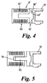
- the sleeve element 8' comprises a main body portion 60 and a capping element 62.
- the main body portion 60 includes the driving surfaces 34' for the tumbler plates and channel means 64 to receive finger means 66 of the capping element 62.
- the capping element includes finger means to be received in the channel means of the main body portion and camming surfaces 38'.
- the capping element 62 is able to move axially with respect to the main body portion 60.
- the capping element 62 includes a surface 40' which rests upon a first surface of the cylinder (not shown) to maintain the capping element 62 in position axially with respect to the cylinder surface (not shown).
- the capping element 62 carrying the camming surfaces 38' is carried axially by the deformed cylinder at least by an amount corresponding to an axial thickness of the crack along the lock housing, i.e. the amount by which the cylinder surface 40 has been axially displaced.
- the camming surface 38' against which the camming surface 44 of the first cap element 10 acts is axially displaced by at least an amount corresponding to the movement of the first surface of the cylinder.
- the capping element may be displaced a further axial distance away from the keyway entry.
- the detent means of the second cap element are carried axially further beyond the location of the cylinder detent means which have been deformed out of position, and as such rotation of the sleeve will no longer cause rotation of the latching finger.
Landscapes
- Engineering & Computer Science (AREA)
- Manufacturing & Machinery (AREA)
- Physics & Mathematics (AREA)
- General Physics & Mathematics (AREA)
- Lock And Its Accessories (AREA)
Abstract
Description
Claims (6)
- A lock assembly comprising a lock housing (4), a lock cylinder (6), a sleeve (8), a first cap element (10), a second cap element (12), a generally "U"-shaped plate (14), spring means (16) and a latching finger (18) is characterised in that the sleeve (8) comprises a first body portion (60) and a second capping portion (62), the first body portion (60) including drive surfaces (34') and keying means (64), the second capping portion (62) including keying means (66) for mating with the keying means (64) of the first body portion (60) and camming surfaces (38'), the lock cylinder (6) comprises a body portion (20) for location within the sleeve (8) and a shaft (22) extending beyond the body portion (20) into the lock housing (4), the body portion (20) including a plurality of tumbler plates (28) and the shaft (22) including detent means (30), the first cap element (10) comprises camming surfaces (44) for mating with the camming surfaces (38') of the sleeve (8) and means (46) for preventing rotation of the first cap element (10) in the lock housing (4), the second cap element (12) being adapted to be carried by and rotatable with respect to the first cap element (10) and comprising detent means (52) adapted for engagement with the cylinder detent means (30) and axially extending members (54), the "U"-shaped locking plate (14) engaging with the cylinder shaft (22) thereby to retain the latching finger (18) on the cylinder shaft (22), the locking plate (14) including means to mate with the axially extending members (54) of the second cap element (12), and the spring means (16) being located between the second cap element (12) and the locking plate (14).
- A lock assembly according to claim 1, characterised in that the first body portion keying means (64) of the sleeve (8) comprises at least one channel in an outer surface of the first body portion (60) and in that the second capping portion keying means (66) of the sleeve (8) comprises at least one axially extending member which is adapted to be received within the at least one channel.
- A lock assembly according to claim 1 or claim 2, characterised in that the camming surfaces (38') of the sleeve (8) extend axially into the camming surfaces (44) of the first cap element (10).
- A lock assembly according to any previous claim, characterised in that the detent surface (30) of the lock cylinder (6) comprises at least one radially extending lug.
- A lock assembly according to any previous claim, characterised in that means to mate the locking plate (14) with the axially extending members (54) of the second cap (12) element comprises a recess in the locking plate (14).
- A lock comprising a lock cylinder (6) and a sleeve (8) for location about the lock cylinder (6), the lock cylinder (6) incorporating detent means (30) including a surface, and the sleeve (8) having a surface (38',44) characterised in that the axial spacing between the sleeve surface (38' ,44) and the detent surface is maintained when the detent means (30) is deformed out of position.
Applications Claiming Priority (2)
| Application Number | Priority Date | Filing Date | Title |
|---|---|---|---|
| GB9910983 | 1999-05-13 | ||
| GB9910983A GB2350146A (en) | 1999-05-13 | 1999-05-13 | Motor vehicle lock assembly |
Publications (2)
| Publication Number | Publication Date |
|---|---|
| EP1052351A2 true EP1052351A2 (en) | 2000-11-15 |
| EP1052351A3 EP1052351A3 (en) | 2001-10-04 |
Family
ID=10853284
Family Applications (1)
| Application Number | Title | Priority Date | Filing Date |
|---|---|---|---|
| EP00303651A Withdrawn EP1052351A3 (en) | 1999-05-13 | 2000-04-28 | Motor vehicle assembly |
Country Status (2)
| Country | Link |
|---|---|
| EP (1) | EP1052351A3 (en) |
| GB (1) | GB2350146A (en) |
Cited By (1)
| Publication number | Priority date | Publication date | Assignee | Title |
|---|---|---|---|---|
| EP1335084A1 (en) * | 2002-01-31 | 2003-08-13 | Valeo Securité Habitacle | Lock cylinder |
Family Cites Families (6)
| Publication number | Priority date | Publication date | Assignee | Title |
|---|---|---|---|---|
| JPS6237473A (en) * | 1985-08-08 | 1987-02-18 | 太田 富夫 | Cylinder lock |
| GB2228523B (en) * | 1989-02-23 | 1993-04-14 | Land Rover Uk Ltd | A locking mechanism |
| ES2073369B1 (en) * | 1993-10-08 | 1999-06-16 | Valeo Sistemas De Seguridad S | DETACHABLE LOCK FOR VEHICLES AND THE LIKE. |
| US5640864A (en) * | 1993-12-27 | 1997-06-24 | Alpha Corporation | Cylinder lock resistible against breaking |
| DE4410783C1 (en) * | 1994-03-28 | 1995-04-27 | Huelsbeck & Fuerst | Closing device with a lock cylinder for a locking function which can be executed particularly on motor vehicles |
| FR2748513B1 (en) * | 1996-05-10 | 1998-06-26 | Valeo Securite Habitacle | AXIAL RELEASE LATCH FOR A MOTOR VEHICLE LOCK MECHANISM |
-
1999
- 1999-05-13 GB GB9910983A patent/GB2350146A/en not_active Withdrawn
-
2000
- 2000-04-28 EP EP00303651A patent/EP1052351A3/en not_active Withdrawn
Cited By (1)
| Publication number | Priority date | Publication date | Assignee | Title |
|---|---|---|---|---|
| EP1335084A1 (en) * | 2002-01-31 | 2003-08-13 | Valeo Securité Habitacle | Lock cylinder |
Also Published As
| Publication number | Publication date |
|---|---|
| GB2350146A (en) | 2000-11-22 |
| EP1052351A3 (en) | 2001-10-04 |
| GB9910983D0 (en) | 1999-07-14 |
Similar Documents
| Publication | Publication Date | Title |
|---|---|---|
| US7472570B2 (en) | Key cylinder | |
| US7007525B2 (en) | Electric steering lock device | |
| US5070716A (en) | Locking mechanism | |
| US6058751A (en) | Free-wheeling lock | |
| EP0659961B1 (en) | Cylinder lock | |
| US8127579B2 (en) | Universal lock cylinder | |
| US4142388A (en) | Tumbler wheels for combination locks | |
| US20020170326A1 (en) | Removable cylindrical lock core | |
| CA1125531A (en) | Torque override threaded locking cap | |
| JP2000038033A (en) | Covering device, especially covering plate for exterior door handle of automobile door | |
| KR20040010346A (en) | Locking system for motor vehicle | |
| KR101298411B1 (en) | Front loading lock assembly | |
| EP4105411B1 (en) | Safety lock | |
| GB2350146A (en) | Motor vehicle lock assembly | |
| US20080168810A1 (en) | Disengageable Lock For Motor Vehicle Locking System | |
| US20090314045A1 (en) | Self-disengaging lock for a car lock mechanism | |
| EP0210962B1 (en) | Anti-theft steering lock device for motor vehicles | |
| EP0892130B1 (en) | Lock cylinder | |
| KR100376433B1 (en) | Free wheeling type locking apparatus | |
| CN108699869B (en) | lock for motor vehicle | |
| CN120925713A (en) | Locking device | |
| CN105756427A (en) | Key cylinder device | |
| EP1536086A1 (en) | Lock with assembly for preventing misregistration of the driven gear that actuates the closing and opening mechanism upon insertion of the cylinder with the key in a lock | |
| KR100383076B1 (en) | Free wheeling type locking apparatus | |
| JPH07189533A (en) | Cylinder lock device |
Legal Events
| Date | Code | Title | Description |
|---|---|---|---|
| PUAI | Public reference made under article 153(3) epc to a published international application that has entered the european phase |
Free format text: ORIGINAL CODE: 0009012 |
|
| AK | Designated contracting states |
Kind code of ref document: A2 Designated state(s): AT BE CH CY DE DK ES FI FR GB GR IE IT LI LU MC NL PT SE |
|
| AX | Request for extension of the european patent |
Free format text: AL;LT;LV;MK;RO;SI |
|
| RAP1 | Party data changed (applicant data changed or rights of an application transferred) |
Owner name: BAYERISCHE MOTOREN WERKE AKTIENGESELLSCHAFT |
|
| PUAL | Search report despatched |
Free format text: ORIGINAL CODE: 0009013 |
|
| AK | Designated contracting states |
Kind code of ref document: A3 Designated state(s): AT BE CH CY DE DK ES FI FR GB GR IE IT LI LU MC NL PT SE |
|
| AX | Request for extension of the european patent |
Free format text: AL;LT;LV;MK;RO;SI |
|
| AKX | Designation fees paid | ||
| REG | Reference to a national code |
Ref country code: DE Ref legal event code: 8566 |
|
| STAA | Information on the status of an ep patent application or granted ep patent |
Free format text: STATUS: THE APPLICATION IS DEEMED TO BE WITHDRAWN |
|
| 18D | Application deemed to be withdrawn |
Effective date: 20020405 |