EP1052143B1 - Driving assistance for vehicle lane changing - Google Patents
Driving assistance for vehicle lane changing Download PDFInfo
- Publication number
- EP1052143B1 EP1052143B1 EP00108242A EP00108242A EP1052143B1 EP 1052143 B1 EP1052143 B1 EP 1052143B1 EP 00108242 A EP00108242 A EP 00108242A EP 00108242 A EP00108242 A EP 00108242A EP 1052143 B1 EP1052143 B1 EP 1052143B1
- Authority
- EP
- European Patent Office
- Prior art keywords
- vehicle
- lane
- road
- guiding aid
- change
- Prior art date
- Legal status (The legal status is an assumption and is not a legal conclusion. Google has not performed a legal analysis and makes no representation as to the accuracy of the status listed.)
- Expired - Lifetime
Links
Images

Classifications
-
- B—PERFORMING OPERATIONS; TRANSPORTING
- B62—LAND VEHICLES FOR TRAVELLING OTHERWISE THAN ON RAILS
- B62D—MOTOR VEHICLES; TRAILERS
- B62D15/00—Steering not otherwise provided for
- B62D15/02—Steering position indicators ; Steering position determination; Steering aids
- B62D15/029—Steering assistants using warnings or proposing actions to the driver without influencing the steering system
-
- B—PERFORMING OPERATIONS; TRANSPORTING
- B60—VEHICLES IN GENERAL
- B60Q—ARRANGEMENT OF SIGNALLING OR LIGHTING DEVICES, THE MOUNTING OR SUPPORTING THEREOF OR CIRCUITS THEREFOR, FOR VEHICLES IN GENERAL
- B60Q9/00—Arrangement or adaptation of signal devices not provided for in one of main groups B60Q1/00 - B60Q7/00, e.g. haptic signalling
- B60Q9/008—Arrangement or adaptation of signal devices not provided for in one of main groups B60Q1/00 - B60Q7/00, e.g. haptic signalling for anti-collision purposes
-
- B—PERFORMING OPERATIONS; TRANSPORTING
- B60—VEHICLES IN GENERAL
- B60T—VEHICLE BRAKE CONTROL SYSTEMS OR PARTS THEREOF; BRAKE CONTROL SYSTEMS OR PARTS THEREOF, IN GENERAL; ARRANGEMENT OF BRAKING ELEMENTS ON VEHICLES IN GENERAL; PORTABLE DEVICES FOR PREVENTING UNWANTED MOVEMENT OF VEHICLES; VEHICLE MODIFICATIONS TO FACILITATE COOLING OF BRAKES
- B60T2201/00—Particular use of vehicle brake systems; Special systems using also the brakes; Special software modules within the brake system controller
- B60T2201/08—Lane monitoring; Lane Keeping Systems
- B60T2201/082—Lane monitoring; Lane Keeping Systems using alarm actuation
-
- B—PERFORMING OPERATIONS; TRANSPORTING
- B60—VEHICLES IN GENERAL
- B60W—CONJOINT CONTROL OF VEHICLE SUB-UNITS OF DIFFERENT TYPE OR DIFFERENT FUNCTION; CONTROL SYSTEMS SPECIALLY ADAPTED FOR HYBRID VEHICLES; ROAD VEHICLE DRIVE CONTROL SYSTEMS FOR PURPOSES NOT RELATED TO THE CONTROL OF A PARTICULAR SUB-UNIT
- B60W50/00—Details of control systems for road vehicle drive control not related to the control of a particular sub-unit, e.g. process diagnostic or vehicle driver interfaces
- B60W50/08—Interaction between the driver and the control system
- B60W50/14—Means for informing the driver, warning the driver or prompting a driver intervention
- B60W2050/143—Alarm means
-
- G—PHYSICS
- G01—MEASURING; TESTING
- G01S—RADIO DIRECTION-FINDING; RADIO NAVIGATION; DETERMINING DISTANCE OR VELOCITY BY USE OF RADIO WAVES; LOCATING OR PRESENCE-DETECTING BY USE OF THE REFLECTION OR RERADIATION OF RADIO WAVES; ANALOGOUS ARRANGEMENTS USING OTHER WAVES
- G01S19/00—Satellite radio beacon positioning systems; Determining position, velocity or attitude using signals transmitted by such systems
- G01S19/01—Satellite radio beacon positioning systems transmitting time-stamped messages, e.g. GPS [Global Positioning System], GLONASS [Global Orbiting Navigation Satellite System] or GALILEO
- G01S19/13—Receivers
- G01S19/14—Receivers specially adapted for specific applications
Definitions
- the invention relates to a Leit Huawei in a lane change of a motor vehicle according to the generic features of claim 1.
- a generic Leit Vietnamese is for example in the DE 43 13 568 C1 disclosed.
- a method for guiding a lane change from a current lane to an adjacent destination lane by a motor vehicle is described.
- the vestibule and the rear space is monitored at least the adjacent target lane for the desired lane change, the distances of objects detected there, in particular vehicles, and their speeds measured and calculated therefrom safety distances. If all measured distances are greater than the calculated safety distances, this is recognized as a possible lane change.
- the driver is thereby largely relieved of monitoring tasks and estimating distances and speeds of subsequent and preceding vehicles.
- This guide aid is preferably used for overtaking and threading on an adjacent lane.
- a side-rearview monitoring device with an object detection unit for detecting objects in a side rear area, a warning display unit in response to the signals of the object detection unit and a recognized lane change request for issuing a warning signal activated.
- the evaluation unit determines whether an object is moving at a higher speed than the own vehicle in a rearward-reaching side rear-space section, and activates if so the warning indicator for issuing a warning signal if it additionally detects a lane change request associated with this side area.
- Lane change requests are preferably detected via the flasher position or the steering angle adjustment.
- the DE 195 07 957 C1 discloses a vehicle having an optical scanning device for a lateral roadway area.
- the vehicle includes as an optical scanning device a plurality of juxtaposed infrared transmitting elements and an associated CCD array and a downstream evaluation unit, which is set up for both contrast determination and contour recognition. With this system, the road surface is scanned to determine a respective roadway boundary. The runtime and contrast determination allows the recognition of lateral lane markings and the determination of the respective vehicle spacing of such markings.
- the invention is therefore the object of developing a generic Leit Vietnamese for a lane change by a motor vehicle such that a more accurate and thus more reliable support the driver takes place at a lane change.
- a significant advantage of these embodiments is that the Leit Vietnamese for a lane change can accurately distinguish whether the follower vehicle is located on the target lane. This is particularly advantageous in the case of a curvy route, since a follower vehicle, which is located in the same lane as the vehicle but is recognized by the side rear space monitoring device, is correctly classified by the guide aid and consequently no warning device is activated. A lane change may occur in this case, although the side-rearview monitoring device detects the following vehicle.
- Lane detection device has detectors, which are preferably arranged on the right and left side of the vehicle and are directed down to the bottom of the lane and thus scan the lane.
- the detectors of the object detection unit are preferably integrated in the two exterior mirrors, with the right detector the right rear side rear space and the left detector picks up the left rear side rear space.
- the Leit Vietnamese is initiated by an activation step 10, which is formed by an operation of a direction indicator lever.
- the activation of the system thus takes place simultaneously with the triggering of the direction indicator.
- the activation of the Leit Vietnamese by a mere tap on the direction indicator lever takes place without the direction indicator is already triggered, so that the other road users are not irritated by the intention of a possibly instantaneously unrealizable lane change.
- the course of the own vehicle is determined in A.
- the lanes are scanned with the lane detection device and recorded with a recording unit, the distance traveled path using the curve radii together with the route.
- B then takes place a determination of the environment of the own vehicle, with the lane detection, the position of the own vehicle to own lane and multi-lane road to other lanes is determined.
- This data can be stored in sections with the recording unit.
- the object detection device With the object detection device the side rear space is monitored, whereby a following vehicle 4, which is located in the monitored side rear space, is detected.
- detectors are preferably arranged on both exterior mirrors, which scan the right and left rear space.
- a relative position assignment of the detected object takes place, wherein from the current location of the own vehicle 0 from the angle ⁇ and the distance 26 of the center of gravity of the object 4 and the stored path of the own vehicle 0 up to this object 4, also the position assignment of this object, ie the follower vehicle 4, relative to the own vehicle 0 is determined.
- an assignment of the follower vehicle 4 takes place on a lane.
- the activation of a warning indication in the vehicle which indicates to the driver that a lane change is not possible, takes place in D.
- the path of the own vehicle is determined in A.
- the course of the path can be recorded via the curve radii (eg with a steering angle sensor and / or from the electronic stability program (ESP and / or ABS signal). at least after each change of one of the signals (curve radius or distance), to determine the amount in longitudinal and transverse direction (convert into X / Y coordinates)
- a two-dimensional model is built / updated and stored for example in a two-dimensional table
- the X-coordinate lies transversely to the direction of travel
- the Y-coordinate in the longitudinal direction After each section and after each change of the radius of curvature, the amount in the longitudinal and transverse direction is to be re-determined over the detection range of the detectors of the object detection unit pendent lateral slippage on an inclined road or in the curve must be compensated by countersteering.
- a position detection device With a position detection device, the position of the own vehicle 0 to the own traffic lane 8 and to further traffic lanes or to the roadside is determined.
- the recording of the road geometry can be done using a lane detection device.
- a turn lane and directional arrows are detected.
- the road geometry data determined in this case are stored and forwarded to the detection area of the detectors and used to determine the course of the road in the rear space.
- the detection of the course of the road in front of the vehicle 0 can additionally be used to determine the course of the road in the rear space.
- detectors are arranged on the vehicle, which scan the space in front of the vehicle.
- the following vehicle 4 is detected by means of the object detection unit.
- the relative position assignment of the detected vehicle 4 is detected in C.
- the relative speed and the distance 26 of the subsequent vehicle 4 detected by the object detection unit are determined by the evaluation unit.
- the direction of the vehicle 4 and from there the angle to the own vehicle is determined by radar sensors or infrared sensors.
- the angle ⁇ and the distance 26 can be determined with optical sensors and image processing by direct detection of the vehicle 4, or the distance in the longitudinal and transverse directions is determined as the x / y value. It is from the current location of the own vehicle 0 on the angle ⁇ and distance of the center of gravity of the vehicle 4 and the stored road course of the own vehicle 0 to the following vehicle 4, the position assignment of the follower vehicle 4 relative to the road.
- the angle ⁇ and the distance 26 of the vehicle 4 are to be converted into the coordinate system of the route.
- the value X of the vehicle 4 at a distance Y is to be compared with the value X of the path at the same distance Y. This comparison provides the information of the way assignment of the vehicle.
- the follower vehicle 4 With identical X values, the follower vehicle 4 is located on the instantaneous lane 8, the same lane 8 as the vehicle 0 itself. If the X value of the vehicle 4 is offset by a road width to the left or right, this vehicle 4 becomes the corresponding adjacent lane 9 assigned.
- a warning signal which is activated by premature detection of a lane change, for example by ambient detection and / or setting a turn signal when the follower vehicle 4 of the target lane 9 is assigned.
- the warning display is preferably integrated in the mirror glass of the exterior mirror.
- a warning signal for example, a red triangle in the exterior mirror flicker.
- Other warning signals such as an acoustic signal tone are also possible.
Description
Die Erfindung betrifft eine Leithilfe bei einem Fahrspurwechsel eines Kraftfahrzeugs gemäß den gattungsbildenden Merkmalen des Anspruchs 1.The invention relates to a Leithilfe in a lane change of a motor vehicle according to the generic features of claim 1.
Eine gattungsgemäße Leithilfe ist beispielsweise in der
In der
Die
Bei dieser Art der Leithilfe für einen Fahrspurwechsel von einer Momentanspur auf eine benachbarte Zielspur durch ein Fahrzeug ist von Nachteil, daß das Folgefahrzeug zwar mit Hilfe einer Seitenrückraumüberwachung erkannt wird, das System aber nicht in der Lage ist eine genaue Zuordnung des Folgefahrzeugs auf eine Fahrspur anzugeben. Dies führt insbesondere bei kurvigen Streckenverläufen, bei welchen ein auf derselben Fahrspur befindliches Folgefahrzeug von der Seitenrückraumüberwachung detektiert wird, zur Erkennung des Folgefahrzeuges als Spurwechselhindernis, obwohl es kein Spurwechselhindernis darstellt.In this type of Leithilfe for a lane change from a current track to an adjacent target lane by a vehicle is a disadvantage that the follower vehicle is indeed detected by means of a Seitenruckraumüberwachung, but the system is not able to provide an accurate assignment of the follower vehicle on a lane , This leads, in particular in curvy routes, in which a follower vehicle located on the same lane is detected by the Seitenrückraumüberwachung, to recognize the following vehicle as a lane change obstacle, although it does not represent a lane change obstacle.
Der Erfindung liegt daher die Aufgabe zugrunde, eine gattungsgemäße Leithilfe für einen Fahrspurwechsel durch ein Kraftfahrzeug derart weiterzubilden, daß eine exaktere und damit zuverlässigere Unterstützung des Fahrers bei einem Fahrspurwechsel erfolgt.The invention is therefore the object of developing a generic Leithilfe for a lane change by a motor vehicle such that a more accurate and thus more reliable support the driver takes place at a lane change.
Erfindungsgemäß wird die Aufgabe durch die Merkmale des Anspruchs 1 gelöst. Vorteilhafte Aus- und Weiterbildungen des Erfindungsgegenstandes sind durch die Merkmale der Unteransprüche gekennzeichnet.According to the invention the object is achieved by the features of claim 1. Advantageous embodiments and further developments of the subject invention are characterized by the features of the subclaims.
Ein wesentlicher Vorteil dieser Ausgestaltungen liegt darin, daß die Leithilfe für einen Fahrspurwechsel genau unterscheiden kann, ob sich das Folgefahrzeug auf der Zielspur befindet. Dies ist insbesondere bei einer kurvenreichen Streckenführung von Vorteil, da ein Folgefahrzeug, das sich auf derselben Fahrspur wie das Fahrzeug befindet, aber von der Seitenrückraumüberwachungseinrichtung erkannt wird, von der Leithilfe richtig eingeordnet und folglich keine Warneinrichtung aktiviert wird. Ein Fahrspurwechsel kann in diesem Fall erfolgen, obwohl die Seitenrückraumüberwachungseinrichtung das Folgefahrzeug detektiert.A significant advantage of these embodiments is that the Leithilfe for a lane change can accurately distinguish whether the follower vehicle is located on the target lane. This is particularly advantageous in the case of a curvy route, since a follower vehicle, which is located in the same lane as the vehicle but is recognized by the side rear space monitoring device, is correctly classified by the guide aid and consequently no warning device is activated. A lane change may occur in this case, although the side-rearview monitoring device detects the following vehicle.
Die Erfindung wird anhand eines Ausführungsbeispieles in Verbindung mit einer Figurenbeschreibung näher erläutert. Es zeigt
- Fig. 1
- einen Ablaufplan einer rechnergesteuerten Leithilfe für einen Fahrspurwechsels,
- Fig. 2
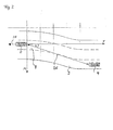
- eine schematische Darstellung einer kurvigen Fahrspur mit Fahrzeug und Folgefahrzeug.
- Fig. 1
- a flowchart of a computer-controlled Leithilfe for a lane change,
- Fig. 2
- a schematic representation of a winding lane with vehicle and follower vehicle.
In der Fahrbahndarstellung in Fig. 2 ist jeweils ein eigenes Fahrzeug 0 auf einer momentanen Fahrspur 8 gezeigt, sowie ein nachfolgendes Fahrzeug 4 auf einer Zielspur 9 gezeigt, wobei die Fahrtrichtung jeweils durch den Pfeil 25 angegeben ist. Der Abstand der beiden Fahrzeuge 0, 4 wird durch den Pfeil 26 bezeichnet. Die Fahrspur liegt in einem X/Y-Koordinatensystem. Fahrspurerkennungseinrichtung weist Detektoren auf, die bevorzugt auf der rechten und linken Seite des Fahrzeuges angeordnet sind und nach unten auf den Boden der Fahrspur gerichtet sind und so die Fahrspur abtasten. Die Detektoren der Objekterfassungseinheit sind bevorzugt in den beiden Außenspiegeln integriert, wobei der rechte Detektor den rechten hinteren Seitenrückraum und der linke Detektor den linken hinteren Seitenrückraum aufnimmt.In the roadway illustration in FIG. 2, a respective vehicle 0 is shown on a current lane 8, and a following
Die Funktionsweise des Verfahrens zur rechnergestützten Leithilfe für einen Fahrspurwechsel von der Momentanspur 8 auf die benachbarte Zielspur 9, die im gezeigten Fall eine in Fahrtrichtung links von der Momentanspur 8 liegende Überholspur darstellt, durch das eigene Fahrzeug 0 wird im folgenden unter Bezugnahme auf den Ablauf der Fig. 1 ausführlich erläutert.The operation of the method for computer-assisted Leithilfe for a lane change from the instantaneous track 8 to the adjacent target track 9, which in the case shown in the direction of travel to the left of the instantaneous lane 8 overtaking lane, by the own vehicle 0 will be described below with reference to the sequence of Fig. 1 explained in detail.
Die Leithilfe wird eingeleitet durch einen Aktivierungsschritt 10, der durch eine Betätigung eines Fahrtrichtungsanzeigehebels gebildet wird. Die Aktivierung des System erfolgt somit gleichzeitig mit dem Auslösen des Fahrtrichtungsanzeigers. Als Alternative kann vorgesehen sein, daß die Aktivierung der Leithilfe durch ein bloßes Antippen des Fahrtrichtungsanzeigehebels erfolgt, ohne daß bereits die Fahrtrichtungsanzeige ausgelöst wird, so daß die anderen Verkehrsteilnehmer nicht durch die Absicht eines möglicherweise augenblicklich noch gar nicht realisierbaren Spurwechsels irritiert werden.The Leithilfe is initiated by an
Zuerst wird in A der Wegverlauf des eigenen Fahrzeuges ermittelt. Hierzu werden die Fahrspuren mit der Fahrspurerkennungseinrichtung abgetastet und mit einer Aufnahmeeinheit der zurückgelegte Wegverlauf mit Hilfe der Kurvenradien zusammen mit der Wegstrecke aufgenommen. In B erfolgt dann eine Bestimmung des Umfeldes des eigenen Fahrzeuges, wobei mit der Fahrspurerkennung die Position des eigenen Fahrzeuges zur eigenen Fahrspur und bei mehrspuriger Fahrbahn zu weiteren Fahrspuren bestimmt wird. Diese Daten können abschnittsweise mit der Aufnahmeeinheit gespeichert werden. Mit der Objekterfassungseinzichtung wird der Seitenrückraum überwacht, wobei ein Folgefahrzeug 4, das sich im überwachten Seitenrückraum befindet, detektiert wird. Hierzu sind bevorzugt an beiden Außenspiegeln Detektoren angeordnet, die den rechten und linken Rückraum abtasten. In C erfolgt eine relative Lagezuordnung des detektierten Objektes, wobei von dem gegenwärtigen Standort des eigenen Fahrzeuges 0 aus über den Winkel α und den Abstand 26 des Schwerpunktes des Objektes 4 und den gespeicherten Wegverlauf des eigenen Fahrzeugs 0 bis zu diesem Objekt 4, auch die Lagezuordnung dieses Objektes, also des Folgefahrzeuges 4, relativ zum eigenen Fahrzeug 0 ermittelt wird. So erfolgt eine Zuordnung des Folgefahrzeuges 4 auf eine Fahrspur. Wenn sich das Folgefahrzeug 4 auf der Zielspur 9 befindet, erfolgt in D die Aktivierung einer Warnanzeige im Fahrzeug, die dem Fahrer anzeigt, daß ein Fahrspurwechsel nicht möglich ist. Im folgenden soll eine ausführliche Beschreibung dieser Punkte erfolgen:First, the course of the own vehicle is determined in A. For this purpose, the lanes are scanned with the lane detection device and recorded with a recording unit, the distance traveled path using the curve radii together with the route. In B then takes place a determination of the environment of the own vehicle, with the lane detection, the position of the own vehicle to own lane and multi-lane road to other lanes is determined. This data can be stored in sections with the recording unit. With the object detection device the side rear space is monitored, whereby a following
In A wird der Wegverlauf des eigenen Fahrzeuges bestimmt: Die Aufzeichnung des Wegverlaufes kann über die Kurvenradien (z.B. mit einem Lenkwinkel-Sensor und/oder aus dem elektronischen Stabilitätsprogramm (ESP- und/oder ABS-Signal) erfolgen. Aus diesen Daten ist abschnittsweise, mindestens nach jeder Änderung eines der Signale (Kurvenradius bzw. Wegstrecke), der Betrag in Längs- und Querrichtung zu ermitteln (in X/Y-Koordinaten umrechnen). Mit diesen Wegedaten wird ein zweidimensionales Modell aufgebaut/aktualisiert und beispielsweise in einer zweidimensionalen Tabelle gespeichert. In einer möglichen Ausführung liegt die X-Koordinate quer zur Fahrtrichtung, die Y-Koordinate in Längsrichtung. Nach jedem Streckenabschnitt und nach jeder Änderung des Kurvenradius ist der Betrag in Längs- und Querrichtung neu zu ermitteln. Die Speicherung des vom Fahrzeug zurückgelegten Wegverlaufs erfolgt über den Erfassungsbereich der Detektoren der Objekterfassungseinheit. Der geschwindigkeitsabhängige seitliche Schlupf auf einer geneigten Fahrbahn oder in der Kurve muß durch Gegenlenken ausgeglichen werden. Hiermit wird -mit dem Lenkwinkelsensor- ein scheinbarer, größerer oder kleinerer Kurvenradius erzeugzt. Anstelle des Lenkwinkelsignals ist mit den Signalen der Raddrehzehlsensoren eine präzisere Erkennung der Kurvenradien erreichbar. Die Erfassung der unterschiedlichen Wegstrecke zwischen innerem und äußerem Rad ist auch mit anderen Methoden wie Radar- oder Infrarot-Verfahren denkbar. Zur Unterstützung kann der Wegverlauf des eigenen Fahrzeugs auch mit Hilfe satellitenunterstützter Verfahren wie GPS (Global Positioning System) erfolgen. In ein Navigationssystem sind die Karten des durchfahrenen Gebietes mittels CD-Rom einlesbar, die den genauen Straßenverlauf beinhalten. Die momentane Lage des eigenen Fahrzeugs auf der Straße wird unterstützend mittels GPS ermittelt.The path of the own vehicle is determined in A. The course of the path can be recorded via the curve radii (eg with a steering angle sensor and / or from the electronic stability program (ESP and / or ABS signal). at least after each change of one of the signals (curve radius or distance), to determine the amount in longitudinal and transverse direction (convert into X / Y coordinates) With this route data, a two-dimensional model is built / updated and stored for example in a two-dimensional table In one possible embodiment, the X-coordinate lies transversely to the direction of travel, the Y-coordinate in the longitudinal direction After each section and after each change of the radius of curvature, the amount in the longitudinal and transverse direction is to be re-determined over the detection range of the detectors of the object detection unit pendent lateral slippage on an inclined road or in the curve must be compensated by countersteering. Hereby, with the steering angle sensor, an apparent, larger or smaller radius of curvature is generated. Instead of the steering angle signal with the signals of Raddrehzehlsensoren a more precise detection of the curve radii can be achieved. The detection of the different distance between the inner and outer wheel is also conceivable with other methods such as radar or infrared methods. To support the course of the own vehicle also with the help of satellites Procedures such as GPS (Global Positioning System) done. In a navigation system, the maps of the area traversed by CD-ROM can be read, which include the exact course of the road. The current position of the own vehicle on the road is supported by GPS.
B Bestimmung des Umfeldes des eigenen Fahrzeuges 0: Mit einer Positionserfassungseinrichtung wird die Position des eigenen Fahrzeuges 0 zur eigenen Fahrspur 8 und zu weiteren Fahrspuren oder zum Straßenrand ermittelt. Die Aufnahme der Straßengeometrie kann mit Hilfe einer Fahrspurerkennungseinrichtung erfolgen. Hierbei wird unterschieden zwischen durchgezogener und gestrichelter Linie. Außerdem wird eine Abbiegespur und Richtungspfeile erkannt. Die hierbei ermittelten Straßengeometriedaten werden gespeichert und bis zum Erfassungsbereich der Detektoren nach hinten weitergereicht und zur Ermittlung des Straßenverlaufs im Rückraum herangezogen. Die Erfassung des Straßenverlaufs vor dem Fahrzeug 0 kann zur Ermittlung des Straßenverlaufs im Rückraum zusätzlich herangezogen werden. Hierzu sind Detektoren am Fahrzeug angeordnet, die den Raum vor dem Fahrzeug abtasten.B Determining the environment of the own vehicle 0: With a position detection device, the position of the own vehicle 0 to the own traffic lane 8 and to further traffic lanes or to the roadside is determined. The recording of the road geometry can be done using a lane detection device. Here, a distinction is made between solid and dashed lines. In addition, a turn lane and directional arrows are detected. The road geometry data determined in this case are stored and forwarded to the detection area of the detectors and used to determine the course of the road in the rear space. The detection of the course of the road in front of the vehicle 0 can additionally be used to determine the course of the road in the rear space. For this purpose, detectors are arranged on the vehicle, which scan the space in front of the vehicle.
In 11 wird mittels Objekterfassungseinheit das Folgefahrzeug 4 detektiert. Die relative Lagezuordnung des detektierten Fahrzeuges 4 wird in C erfaßt: Die Relativgeschwindigkeit und der Abstand 26 des von der Objekterfassungseinheit detektierten, nachfolgenden Fahrzeuges 4 wird von der Auswerteeinheit bestimmt. Die Richtung des Fahrzeuges 4 und daraus der Winkel zum eigenen Fahrzeug wird über Radarsensoren oder Infrarotsensoren ermittelt. Alternativ oder zusätzlich kann mit optischen Sensoren und Bildverarbeitung durch direkte Detektion des Fahrzeuges 4 der Winkel α und der Abstand 26 ermittelt werden oder es wird der Abstand in Längs- und Querrichtung als x/y-Wert ermittelt. Es wird von dem gegenwärtigen Standort des eigenen Fahrzeuges 0 über den Winkel α und Abstand des Schwerpunktes des Fahrzeuges 4 und den gespeicherten Straßenverlauf des eigenen Fahrzeugs 0 bis zum Folgefahrzeug 4, die Lagezuordnung des Folgefahrzeuges 4 relativ zur Straße ermittelt. Dazu ist der Winkel α und der Abstand 26 des Fahrzeuges 4 in das Koordinatensystem des Wegverlaufs umzurechnen. Der Wert X des Fahrzeuges 4 im Abstand Y ist mit dem Wert X des Weges im gleichen Abstand Y zu vergleichen. Dieser Vergleich liefert die Information der Wegezuordnung des Fahrzeuges. Bei identischen X-Werten befindet sich das Folgefahrzeug 4 auf der Momentanspur 8, derselben Fahrspur 8 wie das Fahrzeug 0 selbst. Liegt der X-Wert des Fahrzeuges 4 um eine Straßenbreite nach links oder rechts versetzt, so wird dieses Fahrzeug 4 der entsprechenden Nachbarspur 9 zugeordnet. In D erfolgt im Gefahrenfall, das heißt wenn der Abstand 26 kleiner als ein vorgegebener Sicherheitsabstand ist, die Ausgabe eines Warnsignals, das durch vorzeitige Erkennung eines Spurwechsels, beispielsweise durch Umgebungserkennung und/oder Setzen eines Blinkersignals aktiv geschaltet wird, wenn das Folgefahrzeug 4 der Zielspur 9 zugeordnet wird. Die Warnanzeige ist bevorzugt in das Spiegelglas des Außenspiegels integriert. Als Warnsignal kann beispielsweise ein rotes Dreieck im Außenspiegel aufblinken. Andere Warnsignale, beispielsweise ein akkustischer Signalton sind ebenfalls möglich.11, the following
Claims (8)
- Lane-change guiding aid for a vehicle (0), having an object sensing unit for sensing objects (4) in a rear side spatial region of the vehicle (0), a warning display unit and an evaluation unit which uses the signals fed to it by the object sensing unit to determine whether an object (4) is located in the dead angle section of the monitored side rear space or an object (4) in a section of the monitored side rear space which extends outward to the rear over the dead angle section is moving forward at a higher speed than the driver's own vehicle (0), and if this is the case it activates the warning display unit to output a warning signal if it also detects a lane change request which is associated with the corresponding side region, characterized in that a position sensing device is provided which determines route data of the vehicle (0) and road geometry data in order to determine the position of the driver's own vehicle (0) on the road, and if the object sensing unit detects a following vehicle (4) in the side rear space, a position assignment of the following vehicle (4) relative to the road is determined in accordance with the course of the route travelled along and the road geometry which are indicated with the position sensing device.
- Lane-change guiding aid according to Claim 1, characterized in that if, when a position is assigned, the following vehicle (4) is located on the target lane (9) of the vehicle (0), the warning display unit is activated to output a warning signal.
- Lane-change guiding aid according to Claims 1 and 2, characterized in that the illumination of a red warning triangle in the side mirror is provided as a warning signal.
- Lane-change guiding aid according to Claims 1 to 3, characterized in that the route geometry data and road geometry data relating to the coverage area of the object sensing unit is stored.
- Lane-change guiding aid according to Claims 1 to 4, characterized in that the road geometry data is sensed with optical sensors.
- Lane-change guiding aid according to Claims 1 to 5, characterized in that the route data is determined from a route/speed signal and/or steering angle and/or wheel speed sensors and/or in a satellite-supported fashion by means of GPS.
- Lane-change guiding aid according to Claims 1 to 6, characterized in that the guiding aid is actuated (10) only by the request of a driving direction display, and the requested driving direction display does not take place until a possible lane change is signalled.
- Lane-change guiding aid according to Claims 1 to 7, characterized in that the vehicle (4) is assigned to the corresponding adjacent lane (9) if the vehicle (4) is moved to the left or right by a distance equivalent to the width of the road.
Applications Claiming Priority (2)
| Application Number | Priority Date | Filing Date | Title |
|---|---|---|---|
| DE19921449A DE19921449C1 (en) | 1999-05-08 | 1999-05-08 | Guide assistance when changing the lane of a motor vehicle |
| DE19921449 | 1999-05-08 |
Publications (3)
| Publication Number | Publication Date |
|---|---|
| EP1052143A2 EP1052143A2 (en) | 2000-11-15 |
| EP1052143A3 EP1052143A3 (en) | 2006-03-29 |
| EP1052143B1 true EP1052143B1 (en) | 2007-07-04 |
Family
ID=7907545
Family Applications (1)
| Application Number | Title | Priority Date | Filing Date |
|---|---|---|---|
| EP00108242A Expired - Lifetime EP1052143B1 (en) | 1999-05-08 | 2000-04-14 | Driving assistance for vehicle lane changing |
Country Status (4)
| Country | Link |
|---|---|
| US (1) | US6388565B1 (en) |
| EP (1) | EP1052143B1 (en) |
| JP (1) | JP2001010433A (en) |
| DE (2) | DE19921449C1 (en) |
Cited By (6)
| Publication number | Priority date | Publication date | Assignee | Title |
|---|---|---|---|---|
| CN103797529A (en) * | 2011-09-12 | 2014-05-14 | 日产自动车株式会社 | Three-dimensional object detection device |
| US8842182B2 (en) | 2009-12-22 | 2014-09-23 | Leddartech Inc. | Active 3D monitoring system for traffic detection |
| US8908159B2 (en) | 2011-05-11 | 2014-12-09 | Leddartech Inc. | Multiple-field-of-view scannerless optical rangefinder in high ambient background light |
| US9235988B2 (en) | 2012-03-02 | 2016-01-12 | Leddartech Inc. | System and method for multipurpose traffic detection and characterization |
| US9378640B2 (en) | 2011-06-17 | 2016-06-28 | Leddartech Inc. | System and method for traffic side detection and characterization |
| DE102018220127A1 (en) * | 2018-11-23 | 2020-05-28 | Ford Global Technologies, Llc | Lane change assistance system |
Families Citing this family (83)
| Publication number | Priority date | Publication date | Assignee | Title |
|---|---|---|---|---|
| US6822563B2 (en) | 1997-09-22 | 2004-11-23 | Donnelly Corporation | Vehicle imaging system with accessory control |
| US5877897A (en) | 1993-02-26 | 1999-03-02 | Donnelly Corporation | Automatic rearview mirror, vehicle lighting control and vehicle interior monitoring system using a photosensor array |
| US6891563B2 (en) | 1996-05-22 | 2005-05-10 | Donnelly Corporation | Vehicular vision system |
| US7655894B2 (en) | 1996-03-25 | 2010-02-02 | Donnelly Corporation | Vehicular image sensing system |
| US7593838B2 (en) * | 2000-03-28 | 2009-09-22 | Robert Bosch Gmbh | Model-supported allocation of vehicles to traffic lanes |
| FR2815311B1 (en) * | 2000-10-17 | 2003-01-03 | Peugeot Citroen Automobiles Sa | METHOD FOR INDICATING THE CHANGE OF DIRECTION OF A MOTOR VEHICLE AND DEVICE FOR IMPLEMENTING THE METHOD |
| DE20106977U1 (en) * | 2001-04-23 | 2002-08-29 | Mekra Lang Gmbh & Co Kg | Warning device in motor vehicles |
| DE20110339U1 (en) | 2001-06-22 | 2002-10-24 | Mekra Lang Gmbh & Co Kg | Parking assistance for use in a motor vehicle |
| US6882287B2 (en) | 2001-07-31 | 2005-04-19 | Donnelly Corporation | Automotive lane change aid |
| DE10159658A1 (en) * | 2001-12-05 | 2003-06-26 | Daimler Chrysler Ag | System for automatically following a motor vehicle |
| ES2391556T3 (en) | 2002-05-03 | 2012-11-27 | Donnelly Corporation | Object detection system for vehicles |
| DE10240018B4 (en) * | 2002-08-27 | 2016-09-15 | Volkswagen Ag | Method and device for generating a warning signal before an emergency measure of a driver assistance system of a vehicle |
| DE10242220A1 (en) * | 2002-09-12 | 2004-03-25 | Valeo Schalter Und Sensoren Gmbh | Motor vehicle lane change warning system, comprises a blind angle area-monitoring unit that generates a warning to a driver if another vehicle or obstacle is in the blind angle area |
| DE10251357A1 (en) * | 2002-11-05 | 2004-05-13 | Daimlerchrysler Ag | Automatic operating method for automobile trafficator display with evaluation of data for identification of turning or lane changing maneuver |
| US7697698B2 (en) * | 2003-08-22 | 2010-04-13 | William Sumner Brown | Sound-based vehicle safety system |
| DE10341905A1 (en) * | 2003-09-11 | 2005-05-12 | Daimler Chrysler Ag | Method and device for determining a position of a motor vehicle on a road |
| US7354166B2 (en) * | 2003-11-25 | 2008-04-08 | Temic Automotive Of North America, Inc. | Automatic viewing of vehicle blind spot |
| JP4226455B2 (en) * | 2003-12-16 | 2009-02-18 | 日産自動車株式会社 | Driving intention estimation device, vehicle driving assistance device, and vehicle equipped with vehicle driving assistance device |
| US7349767B2 (en) * | 2003-12-16 | 2008-03-25 | Nissan Motor Co., Ltd. | Method and system for intention estimation and operation assistance |
| JP4281543B2 (en) * | 2003-12-16 | 2009-06-17 | 日産自動車株式会社 | VEHICLE DRIVE OPERATION ASSISTANCE DEVICE AND VEHICLE HAVING VEHICLE DRIVE OPERATION ASSISTANCE DEVICE |
| US7482916B2 (en) | 2004-03-15 | 2009-01-27 | Anita Au | Automatic signaling systems for vehicles |
| US7526103B2 (en) | 2004-04-15 | 2009-04-28 | Donnelly Corporation | Imaging system for vehicle |
| DE102004028613A1 (en) | 2004-06-12 | 2005-12-29 | Robert Bosch Gmbh | Lane change assistant for motor vehicle has detection device for ambient conditions and determined hazard level is dependent on detected ambient conditions in addition to vehicle location data |
| DE102004031771A1 (en) * | 2004-07-01 | 2006-01-26 | Robert Bosch Gmbh | Lane change assistant for motor vehicles |
| US7881496B2 (en) | 2004-09-30 | 2011-02-01 | Donnelly Corporation | Vision system for vehicle |
| JP4246693B2 (en) * | 2004-12-24 | 2009-04-02 | 富士通テン株式会社 | Driving assistance device |
| DE102005002719A1 (en) * | 2005-01-20 | 2006-08-03 | Robert Bosch Gmbh | Course prediction method in driver assistance systems for motor vehicles |
| DE102005003192A1 (en) | 2005-01-24 | 2006-07-27 | Robert Bosch Gmbh | Course prediction method in driver assistance systems for motor vehicles |
| US7474961B2 (en) * | 2005-02-04 | 2009-01-06 | Visteon Global Technologies, Inc. | System to determine the path of a vehicle |
| WO2006092431A1 (en) * | 2005-03-03 | 2006-09-08 | Continental Teves Ag & Co. Ohg | Method and device for avoiding a collision as a vehicle is changing lanes |
| DE102005036714A1 (en) | 2005-08-04 | 2007-02-08 | Daimlerchrysler Ag | Method for assisting the driver of a vehicle in a lane change and driver assistance system for carrying out the method |
| JP4720383B2 (en) * | 2005-09-01 | 2011-07-13 | トヨタ自動車株式会社 | Vehicle control device |
| DE102005054972A1 (en) * | 2005-10-27 | 2007-05-03 | Daimlerchrysler Ag | Motor vehicle`s dead angle monitoring method, involves accomplishing checking of whether lanes change is accomplished based on infrastructure of traffic before warning, where driver warning is omitted if result of checking is not possible |
| DE102007002220A1 (en) * | 2006-01-12 | 2007-07-26 | Continental Teves Ag & Co. Ohg | Method and device for collision warning in the case of lane changes of vehicles |
| DE102006021177A1 (en) * | 2006-05-06 | 2007-11-08 | Bayerische Motoren Werke Ag | Method for the follow-up control of a motor vehicle |
| KR101075615B1 (en) * | 2006-07-06 | 2011-10-21 | 포항공과대학교 산학협력단 | Apparatus and method for generating a auxiliary information of moving vehicles for driver |
| WO2008024639A2 (en) | 2006-08-11 | 2008-02-28 | Donnelly Corporation | Automatic headlamp control system |
| US7786849B2 (en) | 2007-02-02 | 2010-08-31 | Chrysler Group Llc | Trailer detection system |
| US7830243B2 (en) * | 2007-02-02 | 2010-11-09 | Chrysler Group Llc | Dual mode vehicle blind spot system |
| DE102007007540A1 (en) * | 2007-02-15 | 2008-08-21 | Siemens Ag | Object detecting and tracking device for motor vehicle, has object tracking device determining position of detected objects based on position of objects relative to reference vehicle in spatial relation to geometry of lane |
| US20080218381A1 (en) * | 2007-03-05 | 2008-09-11 | Buckley Stephen J | Occupant exit alert system |
| US8428843B2 (en) * | 2008-06-20 | 2013-04-23 | GM Global Technology Operations LLC | Method to adaptively control vehicle operation using an autonomic vehicle control system |
| DE102008054164A1 (en) | 2008-10-31 | 2010-05-12 | Knorr-Bremse Systeme für Nutzfahrzeuge GmbH | Kupplungskompressor- and power steering pump assembly and method for their control |
| US20100152967A1 (en) * | 2008-12-15 | 2010-06-17 | Delphi Technologies, Inc. | Object detection system with learned position information and method |
| ES2344880B1 (en) * | 2008-12-18 | 2011-06-28 | Cion De Galicia Fundacion Para La Promocion De Innovacion, Investigacion Y Desarrollo Tecnolog. En La Ind. De Automo | SYSTEM AND METHOD OF ASSISTANCE TO CHANGE OF LANE WITH ADAPTIVE EVALUATION AREA. |
| US9293047B2 (en) | 2009-01-08 | 2016-03-22 | GM Global Technology Operations LLC | Methods and system for monitoring vehicle movement for use in evaluating possible intersection of paths between vehicle |
| JP5375752B2 (en) * | 2009-07-15 | 2013-12-25 | 日産自動車株式会社 | Vehicle driving support device |
| US9963127B2 (en) * | 2010-01-15 | 2018-05-08 | Volvo Car Corporation | Collision mitigation system and method for braking a vehicle |
| CN102959600B (en) * | 2010-06-29 | 2015-01-14 | 本田技研工业株式会社 | Device for estimating vehicle travel path |
| DE102010054221A1 (en) | 2010-12-11 | 2011-08-25 | Daimler AG, 70327 | Method for assisting driver of motor car during lane change, involves determining lane course of past travel path from information of lane and past travel path, and graphically displaying lane course of past travel distance to driver |
| DE102011016217A1 (en) * | 2011-04-06 | 2012-10-11 | Connaught Electronics Ltd. | Method for warning driver of passenger car before rear end collision, involves projecting path of image, and warning driver of vehicle based on image with projected path, where path is determined based on velocity and steering angle |
| DE102011018159A1 (en) | 2011-04-19 | 2012-10-25 | GM Global Technology Operations LLC (n. d. Gesetzen des Staates Delaware) | Device and method for driver assistance |
| MY180606A (en) * | 2011-08-02 | 2020-12-03 | Nissan Motor | Driving assistance device and driving assistance method |
| US10457209B2 (en) | 2012-02-22 | 2019-10-29 | Magna Electronics Inc. | Vehicle vision system with multi-paned view |
| US9319637B2 (en) | 2012-03-27 | 2016-04-19 | Magna Electronics Inc. | Vehicle vision system with lens pollution detection |
| FR2993847B1 (en) | 2012-07-25 | 2016-04-01 | Peugeot Citroen Automobiles Sa | CHANNEL CHANGE ASSISTANCE SYSTEM FOR A VEHICLE |
| DE102012018120A1 (en) | 2012-09-13 | 2013-03-21 | Daimler Ag | Lane changing assistance system for motor car, has evaluation unit driving rear indicators of car such that light intensity and/or frequency of indicators is increased if alarm is generated and indicating lane change intention on lane |
| US9707896B2 (en) | 2012-10-15 | 2017-07-18 | Magna Electronics Inc. | Vehicle camera lens dirt protection via air flow |
| US9445057B2 (en) | 2013-02-20 | 2016-09-13 | Magna Electronics Inc. | Vehicle vision system with dirt detection |
| EP3056405B1 (en) * | 2013-10-11 | 2018-01-17 | Nissan Motor Co., Ltd | Travel control device and travel control method |
| US9555801B2 (en) * | 2014-03-05 | 2017-01-31 | Denso International America, Inc. | Active steering safety system |
| SE540272C2 (en) * | 2014-04-01 | 2018-05-22 | Scania Cv Ab | Procedure and system for risk assessment of lane change when driving a conductive vehicle on a roadway with at least two adjacent lanes |
| SE540271C2 (en) * | 2014-04-01 | 2018-05-22 | Scania Cv Ab | Procedure for risk assessment of lane change when driving a conductive vehicle on a roadway with at least two adjacent lanes |
| SE540270C2 (en) * | 2014-04-01 | 2018-05-22 | Scania Cv Ab | Procedure and system for risk assessment of lane change when driving a conductive vehicle on a roadway with at least two adjacent lanes |
| US9934690B2 (en) | 2014-06-19 | 2018-04-03 | Hitachi Automotive Systems, Ltd. | Object recognition apparatus and vehicle travel controller using same |
| DE102014013218A1 (en) | 2014-09-05 | 2015-04-02 | Daimler Ag | Driver assistance system for a motor vehicle and method for operating such a driver assistance system |
| WO2016035215A1 (en) | 2014-09-05 | 2016-03-10 | 横浜ゴム株式会社 | Collision avoidance system and collision avoidance method |
| US10488492B2 (en) | 2014-09-09 | 2019-11-26 | Leddarttech Inc. | Discretization of detection zone |
| JP6385907B2 (en) * | 2015-09-25 | 2018-09-05 | 日立オートモティブシステムズ株式会社 | Three-dimensional object detection device |
| DE102016000199A1 (en) * | 2016-01-11 | 2017-07-13 | Trw Automotive Gmbh | Control system and method for determining a safe lane change by motor vehicles |
| DE102016000201A1 (en) * | 2016-01-11 | 2017-07-13 | Trw Automotive Gmbh | Control system and method for determining vehicle lane occupancy |
| DE102016000185A1 (en) | 2016-01-11 | 2017-07-13 | Trw Automotive Gmbh | Control system and method for determining a lane of a subsequent motor vehicle |
| CN105667400B (en) * | 2016-01-19 | 2018-09-21 | 奇瑞汽车股份有限公司 | A kind of right front blind-area visual monitoring alarm system of vehicle |
| US10106076B2 (en) | 2016-02-15 | 2018-10-23 | Ford Global Technologies Llc | Three mode police mirror |
| DE102016202829A1 (en) * | 2016-02-24 | 2017-08-24 | Bayerische Motoren Werke Aktiengesellschaft | Device for transverse guidance support for a road-bound vehicle |
| DE102016202830A1 (en) * | 2016-02-24 | 2017-08-24 | Bayerische Motoren Werke Aktiengesellschaft | Device and method for transverse guidance support for a road-bound vehicle |
| CN105730443B (en) * | 2016-04-08 | 2019-01-01 | 奇瑞汽车股份有限公司 | Vehicle lane change control method and system |
| DE102016212727A1 (en) * | 2016-07-13 | 2018-01-18 | Conti Temic Microelectronic Gmbh | Device and method for adjusting areas for warning a driver |
| JP6610896B2 (en) | 2016-11-28 | 2019-11-27 | トヨタ自動車株式会社 | Vehicle driving support device |
| JP6589840B2 (en) | 2016-12-07 | 2019-10-16 | トヨタ自動車株式会社 | Driving assistance device |
| JP6666883B2 (en) * | 2017-09-01 | 2020-03-18 | 株式会社Subaru | Driving support device |
| CN112319365B (en) * | 2020-10-23 | 2022-01-25 | 浙江中车电车有限公司 | Lane change early warning auxiliary method and system |
| DE102021213571A1 (en) | 2021-11-30 | 2023-06-01 | Volkswagen Aktiengesellschaft | Method and assistance system for supporting a lane change maneuver and motor vehicle |
Family Cites Families (12)
| Publication number | Priority date | Publication date | Assignee | Title |
|---|---|---|---|---|
| IT1240974B (en) * | 1990-07-05 | 1993-12-27 | Fiat Ricerche | METHOD AND EQUIPMENT TO AVOID THE COLLISION OF A VEHICLE AGAINST OBSTACLES. |
| US5583495A (en) * | 1992-09-02 | 1996-12-10 | Ben Lulu; Dani | Vehicle alarm system |
| IT1256956B (en) * | 1992-10-05 | 1995-12-27 | Gilardini Spa | DEVICE TO DETECT RELATIVE POSITIONS BETWEEN VEHICLES, MAINLY IN ANTI-COLLISION FUNCTION. |
| DE4313568C1 (en) * | 1993-04-26 | 1994-06-16 | Daimler Benz Ag | Guiding motor vehicle driver when changing traffic lanes - using radar devices to detect velocity and spacing of vehicles in next lane and indicate when lane changing is possible |
| JPH0717347A (en) * | 1993-07-07 | 1995-01-20 | Mazda Motor Corp | Obstacle detecting device for automobile |
| DE19507957C1 (en) * | 1995-03-07 | 1996-09-12 | Daimler Benz Ag | Vehicle with optical scanning device for a side lane area |
| DE19526452C1 (en) * | 1995-07-20 | 1996-10-10 | Daimler Benz Ag | Side and rear space monitoring device for vehicle |
| JPH09142236A (en) * | 1995-11-17 | 1997-06-03 | Mitsubishi Electric Corp | Periphery monitoring method and device for vehicle, and trouble deciding method and device for periphery monitoring device |
| US5786772A (en) * | 1996-03-22 | 1998-07-28 | Donnelly Corporation | Vehicle blind spot detection display system |
| KR100267541B1 (en) * | 1996-07-26 | 2000-10-16 | 모리 하루오 | Vehicle navigation method and system |
| JPH10166973A (en) | 1996-12-09 | 1998-06-23 | Mitsubishi Motors Corp | Rear and side part alarm device for vehicle |
| US5926126A (en) * | 1997-09-08 | 1999-07-20 | Ford Global Technologies, Inc. | Method and system for detecting an in-path target obstacle in front of a vehicle |
-
1999
- 1999-05-08 DE DE19921449A patent/DE19921449C1/en not_active Expired - Fee Related
-
2000
- 2000-04-14 DE DE50014450T patent/DE50014450D1/en not_active Expired - Lifetime
- 2000-04-14 EP EP00108242A patent/EP1052143B1/en not_active Expired - Lifetime
- 2000-05-08 JP JP2000134519A patent/JP2001010433A/en active Pending
- 2000-05-08 US US09/567,058 patent/US6388565B1/en not_active Expired - Lifetime
Cited By (7)
| Publication number | Priority date | Publication date | Assignee | Title |
|---|---|---|---|---|
| US8842182B2 (en) | 2009-12-22 | 2014-09-23 | Leddartech Inc. | Active 3D monitoring system for traffic detection |
| US8908159B2 (en) | 2011-05-11 | 2014-12-09 | Leddartech Inc. | Multiple-field-of-view scannerless optical rangefinder in high ambient background light |
| USRE47134E1 (en) | 2011-05-11 | 2018-11-20 | Leddartech Inc. | Multiple-field-of-view scannerless optical rangefinder in high ambient background light |
| US9378640B2 (en) | 2011-06-17 | 2016-06-28 | Leddartech Inc. | System and method for traffic side detection and characterization |
| CN103797529A (en) * | 2011-09-12 | 2014-05-14 | 日产自动车株式会社 | Three-dimensional object detection device |
| US9235988B2 (en) | 2012-03-02 | 2016-01-12 | Leddartech Inc. | System and method for multipurpose traffic detection and characterization |
| DE102018220127A1 (en) * | 2018-11-23 | 2020-05-28 | Ford Global Technologies, Llc | Lane change assistance system |
Also Published As
| Publication number | Publication date |
|---|---|
| EP1052143A2 (en) | 2000-11-15 |
| DE50014450D1 (en) | 2007-08-16 |
| DE19921449C1 (en) | 2001-01-25 |
| EP1052143A3 (en) | 2006-03-29 |
| US6388565B1 (en) | 2002-05-14 |
| JP2001010433A (en) | 2001-01-16 |
Similar Documents
| Publication | Publication Date | Title |
|---|---|---|
| EP1052143B1 (en) | Driving assistance for vehicle lane changing | |
| EP3160813B1 (en) | Method for producing a model of the surroundings of a vehicle | |
| EP3094530B1 (en) | Method and system for estimating a course of a traffic lane | |
| EP2493745B1 (en) | Method for support when driving out of a parking space | |
| EP1758755B1 (en) | Driver assistance method and device | |
| EP3253634B1 (en) | Processing of sensor data for a driver assistance system | |
| EP2455250B1 (en) | Method for detecting the environment of a vehicle | |
| EP2673760B1 (en) | Method for assisting a driver of a motor vehicle | |
| DE10110690B4 (en) | Method and device for detecting a lane course | |
| EP2464992B1 (en) | Collision monitoring for vehicle | |
| EP2594461B1 (en) | Method for detecting a parking space for a motor vehicle, parking assistance system and motor vehicle with a parking assistance system | |
| EP2046619B1 (en) | Driver assistance system | |
| WO2007144239A1 (en) | Lane changing aid for motor vehicles | |
| WO2006077182A1 (en) | Driver assistance system with driving path prediction | |
| DE102014208006A1 (en) | Method for detecting the surroundings of a vehicle | |
| DE19851434B4 (en) | Method and device for driver assistance when turning a motor vehicle | |
| DE102005048398A1 (en) | Assistance system for a vehicle driver of a public vehicle feeds mission data such as theoretical speed, destination and safety distances to a computer which is programmed so that it generates a virtual vehicle | |
| DE102006040333A1 (en) | Lane detection method for use in driver assistance system, has reconstructing course of driving lane markings and/or driving lanes in section of driving area from position of driving lane markings, where section lies behind vehicle | |
| DE102012220191A1 (en) | Method for supporting driver during transverse guide of vehicle, involves carrying out steering intervention during collision of vehicle with recognized objects, and determining vehicle data through forward facing camera | |
| EP1684094A2 (en) | Method of optical triangulation for determining distance in automotive applications | |
| EP1612125B1 (en) | Lane-change assistant for motor vehicles | |
| EP1529719B1 (en) | Vehicle guidance apparatus with lateral guiding and object recognition and corresponding method | |
| DE102019204196B4 (en) | Method for detecting the surroundings of a means of locomotion | |
| DE102016008382A1 (en) | A method for assisting a driver of a motor vehicle when maneuvering the motor vehicle and driver assistance system | |
| EP3252502A1 (en) | Method for detecting an incline in a roadway of a motor vehicle, driver assistance system and motor vehicle |
Legal Events
| Date | Code | Title | Description |
|---|---|---|---|
| PUAI | Public reference made under article 153(3) epc to a published international application that has entered the european phase |
Free format text: ORIGINAL CODE: 0009012 |
|
| AK | Designated contracting states |
Kind code of ref document: A2 Designated state(s): AT BE CH CY DE DK ES FI FR GB GR IE IT LI LU MC NL PT SE |
|
| AX | Request for extension of the european patent |
Free format text: AL;LT;LV;MK;RO;SI |
|
| PUAL | Search report despatched |
Free format text: ORIGINAL CODE: 0009013 |
|
| AK | Designated contracting states |
Kind code of ref document: A3 Designated state(s): AT BE CH CY DE DK ES FI FR GB GR IE IT LI LU MC NL PT SE |
|
| AX | Request for extension of the european patent |
Extension state: AL LT LV MK RO SI |
|
| 17P | Request for examination filed |
Effective date: 20060425 |
|
| AKX | Designation fees paid |
Designated state(s): DE ES FR GB IT |
|
| GRAP | Despatch of communication of intention to grant a patent |
Free format text: ORIGINAL CODE: EPIDOSNIGR1 |
|
| RAP1 | Party data changed (applicant data changed or rights of an application transferred) |
Owner name: DAIMLERCHRYSLER AG |
|
| GRAS | Grant fee paid |
Free format text: ORIGINAL CODE: EPIDOSNIGR3 |
|
| GRAA | (expected) grant |
Free format text: ORIGINAL CODE: 0009210 |
|
| AK | Designated contracting states |
Kind code of ref document: B1 Designated state(s): DE ES FR GB IT |
|
| REG | Reference to a national code |
Ref country code: GB Ref legal event code: FG4D Free format text: NOT ENGLISH |
|
| REF | Corresponds to: |
Ref document number: 50014450 Country of ref document: DE Date of ref document: 20070816 Kind code of ref document: P |
|
| GBT | Gb: translation of ep patent filed (gb section 77(6)(a)/1977) |
Effective date: 20070814 |
|
| ET | Fr: translation filed | ||
| RAP2 | Party data changed (patent owner data changed or rights of a patent transferred) |
Owner name: DAIMLER AG |
|
| PG25 | Lapsed in a contracting state [announced via postgrant information from national office to epo] |
Ref country code: ES Free format text: LAPSE BECAUSE OF FAILURE TO SUBMIT A TRANSLATION OF THE DESCRIPTION OR TO PAY THE FEE WITHIN THE PRESCRIBED TIME-LIMIT Effective date: 20071015 |
|
| PLBE | No opposition filed within time limit |
Free format text: ORIGINAL CODE: 0009261 |
|
| STAA | Information on the status of an ep patent application or granted ep patent |
Free format text: STATUS: NO OPPOSITION FILED WITHIN TIME LIMIT |
|
| 26N | No opposition filed |
Effective date: 20080407 |
|
| PG25 | Lapsed in a contracting state [announced via postgrant information from national office to epo] |
Ref country code: IT Free format text: LAPSE BECAUSE OF NON-PAYMENT OF DUE FEES Effective date: 20080430 |
|
| PGFP | Annual fee paid to national office [announced via postgrant information from national office to epo] |
Ref country code: GB Payment date: 20140430 Year of fee payment: 15 |
|
| PGFP | Annual fee paid to national office [announced via postgrant information from national office to epo] |
Ref country code: FR Payment date: 20140428 Year of fee payment: 15 |
|
| REG | Reference to a national code |
Ref country code: DE Ref legal event code: R081 Ref document number: 50014450 Country of ref document: DE Owner name: BERNHARD, WERNER, DIPL.-ING., DE Free format text: FORMER OWNER: DAIMLER AG, 70327 STUTTGART, DE Effective date: 20150408 |
|
| REG | Reference to a national code |
Ref country code: DE Ref legal event code: R084 Ref document number: 50014450 Country of ref document: DE |
|
| GBPC | Gb: european patent ceased through non-payment of renewal fee |
Effective date: 20150414 |
|
| PG25 | Lapsed in a contracting state [announced via postgrant information from national office to epo] |
Ref country code: GB Free format text: LAPSE BECAUSE OF NON-PAYMENT OF DUE FEES Effective date: 20150414 |
|
| REG | Reference to a national code |
Ref country code: FR Ref legal event code: ST Effective date: 20151231 |
|
| PG25 | Lapsed in a contracting state [announced via postgrant information from national office to epo] |
Ref country code: FR Free format text: LAPSE BECAUSE OF NON-PAYMENT OF DUE FEES Effective date: 20150430 |
|
| PGFP | Annual fee paid to national office [announced via postgrant information from national office to epo] |
Ref country code: DE Payment date: 20190430 Year of fee payment: 20 |
|
| REG | Reference to a national code |
Ref country code: DE Ref legal event code: R071 Ref document number: 50014450 Country of ref document: DE |