EP1051992B1 - Rate responsive pacemaker with improved rate change dynamics - Google Patents
Rate responsive pacemaker with improved rate change dynamics Download PDFInfo
- Publication number
- EP1051992B1 EP1051992B1 EP00116324A EP00116324A EP1051992B1 EP 1051992 B1 EP1051992 B1 EP 1051992B1 EP 00116324 A EP00116324 A EP 00116324A EP 00116324 A EP00116324 A EP 00116324A EP 1051992 B1 EP1051992 B1 EP 1051992B1
- Authority
- EP
- European Patent Office
- Prior art keywords
- rate
- sensor
- pacing
- pacemaker
- pacing rate
- Prior art date
- Legal status (The legal status is an assumption and is not a legal conclusion. Google has not performed a legal analysis and makes no representation as to the accuracy of the status listed.)
- Expired - Lifetime
Links
Images


Classifications
-
- A—HUMAN NECESSITIES
- A61—MEDICAL OR VETERINARY SCIENCE; HYGIENE
- A61N—ELECTROTHERAPY; MAGNETOTHERAPY; RADIATION THERAPY; ULTRASOUND THERAPY
- A61N1/00—Electrotherapy; Circuits therefor
- A61N1/18—Applying electric currents by contact electrodes
- A61N1/32—Applying electric currents by contact electrodes alternating or intermittent currents
- A61N1/36—Applying electric currents by contact electrodes alternating or intermittent currents for stimulation
- A61N1/362—Heart stimulators
- A61N1/365—Heart stimulators controlled by a physiological parameter, e.g. heart potential
- A61N1/36585—Heart stimulators controlled by a physiological parameter, e.g. heart potential controlled by two or more physical parameters
Definitions
- the present invention relates to cardiac pacers, and more particularly, to a rate responsive cardiac pacer which automatically controls the speed with which pacing rate can be changed so as to provide a more physiological response to changing cardiac demand.
- rate responsive cardiac pacemaker is now acknowledged to provide a significant improvement over prior fixed-rate cardiac pacemakers.
- rate response techniques have been applied to both single and dual chamber pacemakers, and are able to control pacing rate as a function of one or more measured parameters which are directly or indirectly related to cardiac demand.
- measured parameters include, for example, the physical activity or movement of the patient, right ventricular blood pressure and change of such blood pressure over time, venous blood temperature, venous blood oxygen saturation, respiration, minute ventilation and Q-T interval. See, for example, European patent application No. 0,237,767 by Cordis Corporation, entitled "Rate responsive pacing using the ventricular gradient".
- a problem that pacemaker designers have encountered, but not yet resolved fully satisfactorily, is that of translating sensor indications of desired pacing rate into actual changes in pacing rate.
- the body's physiological response is known to be different from what accurate sensor signals would otherwise indicate.
- the heart does not increase rate as a step function, but increases over a period of time and as a function of the degree of exercise.
- the physiological heart rate decays in accordance with a certain decay function. Accordingly, there have been efforts to resolve the discrepancy between normal heart deceleration function at the end of physiological stresses such as physical activity, and the normal physiological decay function. See, for example, U.S. Application S.N.
- the inventor of this invention has also observed that the appropriate response of a pacemaker to changed sensor indication of heart rate is generally a function of patient history, and specifically recent heart rate (paced or natural). This is a general rule, and is the case not just at transitions from rest to exercise or exercise to rest. Thus, if a patient has already had a relatively high heart rate, e.g., 85 bpm, and the sensor indication calls for a still increased heart rate, the correct physiological response may be different from the situation where the patient starts with a lower heart rate, e.g., around 70 bpm.
- a pacemaker wherein the sensor rate information is analyzed continuously and wherein the rise time for increasing rates and the decay time for decreasing rates are adjusted as a function of patient history such as initial rate, the difference between the sensor indicated rate and present natural rate, and the rate of change of the sensor indicated rate.
- the pacemaker determines an indicated sensor rate (R), the difference between the sensor rate and the then current pacing rate (R-r), and calculates a measure of the time rate of change of R.
- the pacemaker determines whether rate should be incremented or decremented (or left unchanged).
- a first value or change in r ( ⁇ r) is obtained as a function of current pacing rate.
- the measure of time rate of change in R is then compared to a rise threshold figure or a decay threshold figure, depending upon whether a rise or decay in pacing rate is indicated. If the time rate of change in R exceeds the corresponding threshold, a further adjustment to ⁇ r is made, following which pacing rate is increased or decreased by the adjusted ⁇ r.
- control of the per cycle change in pacing rate as set forth above is suitably carried out with the aid of a programmed microprocessor and associated memory.
- the algorithm for carrying out the novel functions of this invention may be supplemented to modify decay time as a function of total patient work during exercise, in accordance with the aforementioned U.S. application S.N. 880,877, which is incorporated herein by reference.
- FIG. 1A there are shown curves which illustrate the problems to be solved by this invention.
- FIG. 1A there are shown two curves correlating pacing rate (r) with a sensed parameter.
- a first curve 30 correlates Q-T interval with pacing rate
- a second curve correlates activity (ACT) with pacing rate.
- each sensor calls for a higher R, and thus a shorter pacing interval.
- the activity sensor is a relatively fast response time sensor, indicating an elevated target pacing rate as shown at R ACT , corresponding to "ACTUAL ACT.”
- the Q-T interval indicates a pacing rate as shown at R QT , corresponding to "ACTUAL QT.” For either sensor, the change from r to R could constitute a large (and unacceptable) jump.
- the pacemaker does not jump directly to the target pacing rate, i.e., immediately switch to a pacing rate R. Rather, the pacemaker may suitably increase rate by an increment ⁇ r which establishes a limit on the rise time of the pacing rate. Likewise, at the cessation of exercise, where R may call for a sharp drop in pacing rate, the pacemaker imposes a decay time which limits the speed with which pacing rate is decreased down toward a normal base rate. See, for example, the discussion in above-referenced S.N. 880,877.
- the rise time or decay time for use in a pacemaker is properly a function of the pacing rate, and should not be a constant value.
- the permitted rise time may vary from a maximum at a relatively low rate to a minimum level at a relatively high rate.
- the initial incremental rise ( ⁇ r) can correspond to an incremental decrease in time interval of, e.g., 20 ms. The value of ⁇ r decreases as the pacing rate is driven upward toward the target rate of 150 bpm.
- the rise time corresponds to a smaller incremental increase in rate, to permit a more physiological step up of pacing rate toward the target rate.
- the initial decay rate can be set to decrement pacing rate at a larger interval (e.g., 20 ms), whereas the decay rate is less for a starting point where the pacing rate was closer to 70 bpm.
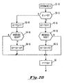
- FIG. 2A there is shown a flow diagram for logic steps to be taken in a pacemaker of this invention.
- the steps may be embodied in software such a contained in microprocessor circuitry 70 as illustrated in Figure 3.
- any equivalent hardware or combination of hardware and software may be utilized for carrying out the steps of determining how to vary the rise time or decay time for a pacemaker of this invention.
- the indicated pacing rate R is determined from the sensor information.
- the absolute difference ⁇ R between R and the present pacing rate (R-r) is determined. If this absolute difference is less than a predetermined minimum amount, ⁇ R is set to zero.
- a measure of the time rate of change of the sensor indicated pacing rate is obtained.
- a calculation of ⁇ R AVG is made, which is an average of ⁇ R over the last n cycles. Thus, if n is a small number, e.g., 2-4, ⁇ R AVG will give an indication of any substantial change in R. Note that also that the change in R-r from the last cycle can also be calculated, and used as a measure of time rate of change of the sensor rate.
- step 38 it is determined whether R-r is greater than zero. If yes, meaning that the pacemaker wants to increase rate, the program branches to block 40.
- pacing rate is set equal to r (the prior pacing rate) + ⁇ r. Going back to block 38, if the answer is no, this means that the pacemaker wants to decrease pacing rate, and select a decay time.
- ⁇ r is set equal to f 2 (r). The program then goes to block 54 and compares ⁇ R AVG to a second stored threshold ⁇ R TH2 . If this comparison is positive, then ⁇ r is further decremented by ⁇ 2 at 56, to decrease pacing rate at a greater decay rate.
- Figure 2A is reflective simply of logic steps taken to adjust the rise time or the decay time of the pacer response as a function of pacing rate and time rate of change of the sensor indicated rate. These steps may be combined with other logic decisions, such as consideration of total work done during exercise, as set forth in the above-mentioned application entitled "Work-Modulated Pacing Rate Deceleration.” Further, rise time and/or decay time may be modulated as a function of a second sensor. Thus, if sensor rate r is determined primarily or solely from a first parameter such as Q-T interval, a second faster response sensor such as a typical activity sensor may be used to control rise time or decay time. For this embodiment, as seen in Fig.
- R is obtained from a first sensor, at 32-B.
- rate should be incremented or decremented. If incremented, at 40-B ⁇ r is made equal to f 1 (r). Then, at 44B, the second sensor is monitored, to see if a faster response is indicated. If yes, ⁇ r is set equal to ⁇ r + ⁇ 3 at 46-B. If it is determined that rate should be decremented, at 50-B, ⁇ r is made equal to f 2 (r). Then, at 54-B, the second sensor signal is examined to determine whether a faster decay is indicated. If yes, at 56-B, ⁇ r is set equal to ⁇ r - ⁇ 4.
- Microprocessor circuitry 70 is illustrated, being comprised of microprocessor unit 70 and associated memory 72.
- the microprocessor itself may have built-in memory, in which case memory 72 is additional memory.
- the microprocessor circuitry is connected by data communication bus 73 to hardware block 75, and specifically to digital logic and control circuitry 76.
- This control circuitry is used for a number of conventional pacemaker operations, including controlling the timing, shape and size of output stimulus pulses.
- the digital logic and control circuitry 76 provides control signals to circuitry 81, which may generate atrial pace and/or ventricular pace pulses, which pulses are coupled on lead 83 to the atrium and/or the ventricle of the patient.
- sensor 77 is shown, illustrated as an external sensor, which generates signals which are coupled through to amplifier and processing circuitry 78, and in turn coupled to circuitry 76 for developing of the R signal.
- Sensor 77 may be one or more external sensors, including a fast time-response sensor as discussed below, and may be utilized along with the Q-T signal, which latter signal is developed from the V sense circuitry in a known manner.
- an external programmer 86 may be used which communicates with the pacemaker through transmit receive circuitry 87 in a standard fashion.
- rate increments can be determined to include either ⁇ 1 and/or ⁇ 3, and rate decrements can be determined to include either ⁇ 2 and/or ⁇ 4.
- changes can be determined as a function of pacing rate; time rate of change of the sensor-indicated pacing rate, and/or an extra sensor chosen to provide a fast time response. The contribution of the extra sensor in this arrangement is to accelerate the change of r so as to more quickly decrease the R-r difference.
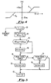
- ⁇ r may be determined from a function f3, as illustrated in Figure 4.
- ⁇ r is zero until the magnitude of R-r exceeds a predetermined limit; ⁇ r then increases linearly to a maximum value, such as 20 ms, and remains at such maximum value for even greater magnitudes (positive or negative values) of R-r.
- the increment in pacing rate ( ⁇ r) can be modified depending upon whether the prior cycles were terminated with sensed natural beats, or paced beats. For example, the prior n cycles can be examined to determine if all resulted in sensed beats, or all resulted in paced beats. If sensed beats, the increase in ⁇ r is limited, so that the sensor is not allowed to overtake the natural rate too quickly. If the prior n beats were paced, then the ⁇ r increment can be made greater. This variation is illustrated in Figure 5, which is a variation of Figure 2A. As there illustrated, at 40, ⁇ r is determined following a finding that R-r is positive, by using either the f1 or f3 function.
Description
- The present invention relates to cardiac pacers, and more particularly, to a rate responsive cardiac pacer which automatically controls the speed with which pacing rate can be changed so as to provide a more physiological response to changing cardiac demand.
- The rate responsive cardiac pacemaker is now acknowledged to provide a significant improvement over prior fixed-rate cardiac pacemakers. Indeed, rate response techniques have been applied to both single and dual chamber pacemakers, and are able to control pacing rate as a function of one or more measured parameters which are directly or indirectly related to cardiac demand. Such measured parameters include, for example, the physical activity or movement of the patient, right ventricular blood pressure and change of such blood pressure over time, venous blood temperature, venous blood oxygen saturation, respiration, minute ventilation and Q-T interval. See, for example, European patent application No. 0,237,767 by Cordis Corporation, entitled "Rate responsive pacing using the ventricular gradient".
- A more recent advent is the employment of two or more sensors and the use of algorithms for obtaining an optimized sensor-heart rate correlation function. See, for example, U.S. Patent No. 5,065,759, entitled "Pacemaker With Optimized Rate Responsiveness and Method of Rate Control," assigned to the same assignee as this application. An advantage of the combined sensor approach is to provide a sensor response which accurately tracks cardiac demand both during fast time period episodes and during more stable steady state patient conditions. For example, the Q-T parameter is very reliable as a steady state indicator of metabolic demand, but does not respond quickly to fast changes, such as at the onset of exercise. On the other hand, the activity-type sensor, such as described in U.S. Patent No. 4,485,813, issued to Anderson et al., and assigned to Medtronic, Inc., provides a faster response to changing patient conditions, even though it may not be as accurate an indicator of quiescent demand.
- A problem that pacemaker designers have encountered, but not yet resolved fully satisfactorily, is that of translating sensor indications of desired pacing rate into actual changes in pacing rate. By way of example, at both the onset and termination of exercise the body's physiological response is known to be different from what accurate sensor signals would otherwise indicate. Thus, at the onset of exercise, the heart does not increase rate as a step function, but increases over a period of time and as a function of the degree of exercise. Likewise, following termination of exercise, the physiological heart rate decays in accordance with a certain decay function. Accordingly, there have been efforts to resolve the discrepancy between normal heart deceleration function at the end of physiological stresses such as physical activity, and the normal physiological decay function. See, for example, U.S. Application S.N. 07/567,204, filed August 14, 1990, Bennett et al., entitled "Rate Responsive Pacemaker and Pacing Method"; and U.S. Patent Application S.N. 880,877, filed May 11, 1992, "Work-Modulated Pacing Rate Deceleration," both assigned to Medtronic, Inc.
- The inventor of this invention has also observed that the appropriate response of a pacemaker to changed sensor indication of heart rate is generally a function of patient history, and specifically recent heart rate (paced or natural). This is a general rule, and is the case not just at transitions from rest to exercise or exercise to rest. Thus, if a patient has already had a relatively high heart rate, e.g., 85 bpm, and the sensor indication calls for a still increased heart rate, the correct physiological response may be different from the situation where the patient starts with a lower heart rate, e.g., around 70 bpm.
- As a consequence of the above observations, it is seen that there is a need for an improved pacemaker apparatus, and method of controlling the rate responsiveness of a pacemaker, for providing a more appropriately physiological response under conditions where accurate sensor information concerning cardiac demand is available.
- It is an object of this invention to provide a rate responsive pacemaker with improved rate change dynamics whereby changes in pacing rate, both rise and decay, follow an improved and more physiological pattern.
- In accordance with the present invention, there is provided a pacemaker, wherein the sensor rate information is analyzed continuously and wherein the rise time for increasing rates and the decay time for decreasing rates are adjusted as a function of patient history such as initial rate, the difference between the sensor indicated rate and present natural rate, and the rate of change of the sensor indicated rate. Preferably on a cycle-by-cycle basis the pacemaker determines an indicated sensor rate (R), the difference between the sensor rate and the then current pacing rate (R-r), and calculates a measure of the time rate of change of R. The pacemaker then determines whether rate should be incremented or decremented (or left unchanged). A first value or change in r (Δr) is obtained as a function of current pacing rate. The measure of time rate of change in R is then compared to a rise threshold figure or a decay threshold figure, depending upon whether a rise or decay in pacing rate is indicated. If the time rate of change in R exceeds the corresponding threshold, a further adjustment to Δr is made, following which pacing rate is increased or decreased by the adjusted Δr.
- The control of the per cycle change in pacing rate as set forth above, is suitably carried out with the aid of a programmed microprocessor and associated memory. The algorithm for carrying out the novel functions of this invention may be supplemented to modify decay time as a function of total patient work during exercise, in accordance with the aforementioned U.S. application S.N. 880,877, which is incorporated herein by reference.
-
- Figure 1A presents curves showing correlation of Q-T interval with pacing rate, and a measure of activity (ACT) with pacing rate.
- Figure 1B is an graph indicating pacing rate increment versus pacing rate, for both rise and decay situations.
- Figures 2A and 2B are flow diagrams depicting the operation of a control algorithm in accordance with this invention, for controlling the pacing rate increment as a function of pacing rate and/or time rate of change of the sensor rate.
- Figure 3 is a block diagram of the main components of a pacemaker in accordance with this invention.
- Figure 4 is a graph indicating pacing rate increment versus the difference between sensor rate and current pacing rate (R-r).
- Figure 5 is a flow diagram showing the primary logic steps for controlling pacing rate increment as a function of whether prior cycles have ended with sensed or paced events.
-
- Referring now to Figures 1A and 1B, there are shown curves which illustrate the problems to be solved by this invention. As seen in Figure 1A, there are shown two curves correlating pacing rate (r) with a sensed parameter. Thus, a
first curve 30 correlates Q-T interval with pacing rate, and a second curve correlates activity (ACT) with pacing rate. These curves are given for illustrative purposes only, and it is understood that the precise correlation curve between the sensed parameter and pacing rate may be adjusted for any given patient. Reference is made to U.S. Patent No. 5,065,759, entitled "Pacemaker With Optimized Rate Responsiveness and Method of Rate Control," which discloses an arrangement for utilizing two parameters to obtain an indication of desired pacing rate. As used in this invention, reference to the sensor signal, or indicated sensor rate (R), may refer to either one or plural sensors. - The situation where there has been a sharp increase in exercise level of the patient is illustrated. Prior to the increase in exercise, it is assumed that pacing rate corresponded to the point "X" on each of the curves. Following the increase in exercise, each sensor calls for a higher R, and thus a shorter pacing interval. The activity sensor is a relatively fast response time sensor, indicating an elevated target pacing rate as shown at RACT, corresponding to "ACTUAL ACT." The Q-T interval indicates a pacing rate as shown at RQT, corresponding to "ACTUAL QT." For either sensor, the change from r to R could constitute a large (and unacceptable) jump. In practice, the pacemaker does not jump directly to the target pacing rate, i.e., immediately switch to a pacing rate R. Rather, the pacemaker may suitably increase rate by an increment Δr which establishes a limit on the rise time of the pacing rate. Likewise, at the cessation of exercise, where R may call for a sharp drop in pacing rate, the pacemaker imposes a decay time which limits the speed with which pacing rate is decreased down toward a normal base rate. See, for example, the discussion in above-referenced S.N. 880,877.
- As discussed above, it is my observation that the rise time or decay time for use in a pacemaker is properly a function of the pacing rate, and should not be a constant value. Thus, the permitted rise time may vary from a maximum at a relatively low rate to a minimum level at a relatively high rate. As illustrated in Fig. 1B, if a patient's rate has been at about 70 bpm, and the sensor rate R is indicated at a higher rate such as 150 bpm, the initial incremental rise (Δr) can correspond to an incremental decrease in time interval of, e.g., 20 ms. The value of Δr decreases as the pacing rate is driven upward toward the target rate of 150 bpm. Thus, if a patient had started with a rate of about 90 bpm, and then underwent an increase in exercise, the rise time corresponds to a smaller incremental increase in rate, to permit a more physiological step up of pacing rate toward the target rate. Likewise, when a patient has been paced at a relatively high rate (e.g., 150 bpm) and there is termination of exercise, the initial decay rate can be set to decrement pacing rate at a larger interval (e.g., 20 ms), whereas the decay rate is less for a starting point where the pacing rate was closer to 70 bpm.
- Referring now to Figure 2A, there is shown a flow diagram for logic steps to be taken in a pacemaker of this invention. Suitably the steps may be embodied in software such a contained in
microprocessor circuitry 70 as illustrated in Figure 3. However, any equivalent hardware or combination of hardware and software may be utilized for carrying out the steps of determining how to vary the rise time or decay time for a pacemaker of this invention. - At step 32, the indicated pacing rate R is determined from the sensor information. At step 34, the absolute difference ΔR between R and the present pacing rate (R-r) is determined. If this absolute difference is less than a predetermined minimum amount, ΔR is set to zero. At step 36, a measure of the time rate of change of the sensor indicated pacing rate is obtained. A calculation of ΔRAVG is made, which is an average of ΔR over the last n cycles. Thus, if n is a small number, e.g., 2-4, ΔRAVG will give an indication of any substantial change in R. Note that also that the change in R-r from the last cycle can also be calculated, and used as a measure of time rate of change of the sensor rate. At
step 38, it is determined whether R-r is greater than zero. If yes, meaning that the pacemaker wants to increase rate, the program branches to block 40. At 40, Δr is obtained from memory in accordance with the formula Δr = f1(r) shown as the rise curve in Figure 1B. Following this, the program proceeds to block 44 and determines whether ΔRAVG is greater than ΔRTH1, a predetermined stored value. This comparison determines whether there has been a substantial change in R, indicating that a further more aggressive change in pacing rate is in order. If no, the program branches to block 60, but if yes, the program branches to block 46 and increments Δr by a factor Δ1. Then atblock 60, pacing rate is set equal to r (the prior pacing rate) + Δr. Going back to block 38, if the answer is no, this means that the pacemaker wants to decrease pacing rate, and select a decay time. At block 50, Δr is set equal to f2(r). The program then goes to block 54 and compares ΔRAVG to a second stored threshold ΔRTH2. If this comparison is positive, then Δr is further decremented by Δ2 at 56, to decrease pacing rate at a greater decay rate. - It is to be understood that Figure 2A is reflective simply of logic steps taken to adjust the rise time or the decay time of the pacer response as a function of pacing rate and time rate of change of the sensor indicated rate. These steps may be combined with other logic decisions, such as consideration of total work done during exercise, as set forth in the above-mentioned application entitled "Work-Modulated Pacing Rate Deceleration." Further, rise time and/or decay time may be modulated as a function of a second sensor. Thus, if sensor rate r is determined primarily or solely from a first parameter such as Q-T interval, a second faster response sensor such as a typical activity sensor may be used to control rise time or decay time. For this embodiment, as seen in Fig. 2B, R is obtained from a first sensor, at 32-B. At 38-B it is determined whether rate should be incremented or decremented. If incremented, at 40-B Δr is made equal to f1(r). Then, at 44B, the second sensor is monitored, to see if a faster response is indicated. If yes, Δr is set equal to Δr + Δ3 at 46-B. If it is determined that rate should be decremented, at 50-B, Δr is made equal to f2(r). Then, at 54-B, the second sensor signal is examined to determine whether a faster decay is indicated. If yes, at 56-B, Δr is set equal to Δr - Δ4.
- Referring now to Figure 3, there is shown a block diagram of the major components of a pacemaker in accordance with this invention.
Microprocessor circuitry 70 is illustrated, being comprised ofmicroprocessor unit 70 and associatedmemory 72. The microprocessor itself may have built-in memory, in whichcase memory 72 is additional memory. The microprocessor circuitry is connected bydata communication bus 73 tohardware block 75, and specifically to digital logic andcontrol circuitry 76. This control circuitry is used for a number of conventional pacemaker operations, including controlling the timing, shape and size of output stimulus pulses. The digital logic andcontrol circuitry 76 provides control signals tocircuitry 81, which may generate atrial pace and/or ventricular pace pulses, which pulses are coupled onlead 83 to the atrium and/or the ventricle of the patient. Signals sensed from the heart are coupled throughsense circuitry 82 back through to the logic andcontrol circuitry 76. In addition, sensor 77 is shown, illustrated as an external sensor, which generates signals which are coupled through to amplifier andprocessing circuitry 78, and in turn coupled tocircuitry 76 for developing of the R signal. Sensor 77 may be one or more external sensors, including a fast time-response sensor as discussed below, and may be utilized along with the Q-T signal, which latter signal is developed from the V sense circuitry in a known manner. Additionally, anexternal programmer 86 may be used which communicates with the pacemaker through transmit receivecircuitry 87 in a standard fashion. - It is to be understood that variations of the disclosed preferred embodiments are within the scope of the invention. Thus, the invention may embody a combination of Figures 2A and 2B. In such a combination, rate increments can be determined to include either Δ1 and/or Δ3, and rate decrements can be determined to include either Δ2 and/or Δ4. In this way, changes can be determined as a function of pacing rate; time rate of change of the sensor-indicated pacing rate, and/or an extra sensor chosen to provide a fast time response. The contribution of the extra sensor in this arrangement is to accelerate the change of r so as to more quickly decrease the R-r difference.
- Another embodiment of this invention involves controlling Δr as a function of the determined magnitude of the R-r value. Thus, instead of using one of the functions f1 or f2, as illustrated in Figure 1B, Δr may be determined from a function f3, as illustrated in Figure 4.
- In Fig 4, Δr is zero until the magnitude of R-r exceeds a predetermined limit; Δr then increases linearly to a maximum value, such as 20 ms, and remains at such maximum value for even greater magnitudes (positive or negative values) of R-r. In this embodiment, steps 40 and 50 illustrated in Figure 2A become "get Δr = f3 (R-r).
- In yet another variation of this invention, the increment in pacing rate (Δr) can be modified depending upon whether the prior cycles were terminated with sensed natural beats, or paced beats. For example, the prior n cycles can be examined to determine if all resulted in sensed beats, or all resulted in paced beats. If sensed beats, the increase in Δr is limited, so that the sensor is not allowed to overtake the natural rate too quickly. If the prior n beats were paced, then the Δr increment can be made greater. This variation is illustrated in Figure 5, which is a variation of Figure 2A. As there illustrated, at 40, Δr is determined following a finding that R-r is positive, by using either the f1 or f3 function. Following
blocks block 70 it is determined of the prior events have been sense events. If yes, Δr is decremented at 72; if no, the routine goes to 74, and determines whether the prior events have been paces. If yes, Δr is decremented by Δ3 atblock 76.
Claims (2)
- A rate responsive cardiac pacemaker, having a rate controllable pulse generator (81) for generating stimulus pulses, sensor means (72, 32) for obtaining a sensor rate indication (R) which indicates desired pacing rate, and rate control means (71, Fig. 2A) for developing a rate control signal for controlling said pulse generator to operate at a pacing rate, characterized by said rate control means having rate means (36) for determining a measure of the difference between the sensor rate and the present pacing rate just prior to the current pacemaker cycle, and said rate control means comprising adjusting means (38; 40, 44, 46; 50, 54, 56; 60) for adjusting said pacing rate as a function of said measure of the difference between the sensor rate and the present pacing rate.
- The pacemaker as described in claim 1, wherein said adjustment means further comprises means (70, 74) for adjusting said pacing rate as a function of whether prior pacemaker cycles ended in sensed or paced events.
Applications Claiming Priority (3)
| Application Number | Priority Date | Filing Date | Title |
|---|---|---|---|
| US08/132,758 US5470344A (en) | 1993-10-06 | 1993-10-06 | Rate responsive pacemake with improved rate change dynamics and pacing method |
| US132758 | 1993-10-06 | ||
| EP94115769A EP0647454B1 (en) | 1993-10-06 | 1994-10-06 | Rate responsive pacemaker with improved rate change dynamics |
Related Parent Applications (1)
| Application Number | Title | Priority Date | Filing Date |
|---|---|---|---|
| EP94115769A Division EP0647454B1 (en) | 1993-10-06 | 1994-10-06 | Rate responsive pacemaker with improved rate change dynamics |
Publications (3)
| Publication Number | Publication Date |
|---|---|
| EP1051992A2 EP1051992A2 (en) | 2000-11-15 |
| EP1051992A3 EP1051992A3 (en) | 2000-11-22 |
| EP1051992B1 true EP1051992B1 (en) | 2005-04-20 |
Family
ID=22455467
Family Applications (2)
| Application Number | Title | Priority Date | Filing Date |
|---|---|---|---|
| EP00116324A Expired - Lifetime EP1051992B1 (en) | 1993-10-06 | 1994-10-06 | Rate responsive pacemaker with improved rate change dynamics |
| EP94115769A Expired - Lifetime EP0647454B1 (en) | 1993-10-06 | 1994-10-06 | Rate responsive pacemaker with improved rate change dynamics |
Family Applications After (1)
| Application Number | Title | Priority Date | Filing Date |
|---|---|---|---|
| EP94115769A Expired - Lifetime EP0647454B1 (en) | 1993-10-06 | 1994-10-06 | Rate responsive pacemaker with improved rate change dynamics |
Country Status (3)
| Country | Link |
|---|---|
| US (1) | US5470344A (en) |
| EP (2) | EP1051992B1 (en) |
| DE (2) | DE69434346T2 (en) |
Families Citing this family (7)
| Publication number | Priority date | Publication date | Assignee | Title |
|---|---|---|---|---|
| FR2713094B1 (en) * | 1993-12-06 | 1996-01-19 | Ela Medical Sa | Implantable frequency-controlled cardiac simulator and its control method. |
| FR2734730B1 (en) * | 1995-05-31 | 1997-08-22 | Ela Medical Sa | ACTIVE IMPLANTABLE MEDICAL DEVICE, IN PARTICULAR A CARDIAC STIMULATOR OR DEFRIBRILLATOR |
| SE9603635D0 (en) | 1996-10-04 | 1996-10-04 | Pacesetter Ab | Implantable stimulator |
| DE19900690C1 (en) | 1999-01-05 | 2000-05-18 | Pacesetter Ab Jaerfaella | Heart pacemaker reduces and increases stimulation interval so that mean interval does not change and determines electrical restitution of heart for this mean interval by measuring action potential duration |
| US6836682B2 (en) | 2001-11-16 | 2004-12-28 | Medtronic, Inc. | Rate responsive pacing system with QT sensor based on intrinsic QT data |
| US20040215277A1 (en) * | 2003-04-25 | 2004-10-28 | Peter Oosterhoff | Dynamic pacing interval extension for detection of intrinsic ventricular activity |
| US7957801B2 (en) * | 2003-04-25 | 2011-06-07 | Medtronic, Inc. | Dynamic pacing interval extension for detection of intrinsic ventricular activity |
Family Cites Families (15)
| Publication number | Priority date | Publication date | Assignee | Title |
|---|---|---|---|---|
| US4091726A (en) * | 1976-11-02 | 1978-05-30 | Joseph E. Podgor, Inc. | Magnetic registration apparatus for silk screen printer |
| US4485813A (en) * | 1981-11-19 | 1984-12-04 | Medtronic, Inc. | Implantable dynamic pressure transducer system |
| US4782836A (en) * | 1984-05-24 | 1988-11-08 | Intermedics, Inc. | Rate adaptive cardiac pacemaker responsive to patient activity and temperature |
| DE3419439C1 (en) * | 1984-05-24 | 1985-11-21 | Eckhard Dr. 8000 München Alt | Frequency-dependent pacemaker depending on the load |
| US4708143A (en) * | 1984-07-19 | 1987-11-24 | Cordis Leads Inc. | Method for controlling pacing of a heart in response to changes in stroke volume |
| US4566456A (en) * | 1984-10-18 | 1986-01-28 | Cordis Corporation | Apparatus and method for adjusting heart/pacer rate relative to right ventricular systolic pressure to obtain a required cardiac output |
| DE3787186T2 (en) * | 1986-03-19 | 1994-05-05 | Telectronics Nv | Clock-sensitive stimulation using the ventricular gradient. |
| DE68927447T2 (en) * | 1988-02-17 | 1997-04-03 | Stuart Charles Webb | Frequency-sensitive pacemaker |
| US5052388A (en) * | 1989-12-22 | 1991-10-01 | Medtronic, Inc. | Method and apparatus for implementing activity sensing in a pulse generator |
| US5134997A (en) * | 1990-08-14 | 1992-08-04 | Medtronic, Inc. | Rate responsive pacemaker and pacing method |
| US5158078A (en) * | 1990-08-14 | 1992-10-27 | Medtronic, Inc. | Rate responsive pacemaker and methods for optimizing its operation |
| US5065759A (en) * | 1990-08-30 | 1991-11-19 | Vitatron Medical B.V. | Pacemaker with optimized rate responsiveness and method of rate control |
| US5144949A (en) * | 1991-03-15 | 1992-09-08 | Medtronic, Inc. | Dual chamber rate responsive pacemaker with automatic mode switching |
| IT1245814B (en) * | 1991-05-21 | 1994-10-18 | Sorin Biomedica Spa | RATE RESPONSIVE CARDIOSTIMULATOR DEVICE |
| US5312453A (en) * | 1992-05-11 | 1994-05-17 | Medtronic, Inc. | Rate responsive cardiac pacemaker and method for work-modulating pacing rate deceleration |
-
1993
- 1993-10-06 US US08/132,758 patent/US5470344A/en not_active Expired - Lifetime
-
1994
- 1994-10-06 DE DE69434346T patent/DE69434346T2/en not_active Expired - Lifetime
- 1994-10-06 EP EP00116324A patent/EP1051992B1/en not_active Expired - Lifetime
- 1994-10-06 DE DE69430892T patent/DE69430892T2/en not_active Expired - Lifetime
- 1994-10-06 EP EP94115769A patent/EP0647454B1/en not_active Expired - Lifetime
Also Published As
| Publication number | Publication date |
|---|---|
| EP0647454A3 (en) | 1997-02-05 |
| US5470344A (en) | 1995-11-28 |
| DE69430892T2 (en) | 2003-02-06 |
| EP1051992A3 (en) | 2000-11-22 |
| DE69434346T2 (en) | 2006-03-09 |
| EP0647454B1 (en) | 2002-07-03 |
| EP1051992A2 (en) | 2000-11-15 |
| DE69430892D1 (en) | 2002-08-08 |
| EP0647454A2 (en) | 1995-04-12 |
| DE69434346D1 (en) | 2005-05-25 |
Similar Documents
| Publication | Publication Date | Title |
|---|---|---|
| EP0545971B1 (en) | Pacemaker with optimized rate responsiveness | |
| US5312453A (en) | Rate responsive cardiac pacemaker and method for work-modulating pacing rate deceleration | |
| US5158078A (en) | Rate responsive pacemaker and methods for optimizing its operation | |
| US4972834A (en) | Pacemaker with improved dynamic rate responsiveness | |
| JP3340819B2 (en) | Cardiac pacemaker | |
| US5144950A (en) | Rate controlled pacemaker system using ar interval for rate control | |
| US6477418B2 (en) | Implantable heart stimulation system with automatic mode switching controlled by sympatho-vagal balance | |
| US5350409A (en) | Rate adaptive pacemaker with adjustment of sensor rate as a function of sensed sinus rate | |
| EP0363015B1 (en) | Rate stabilization pacemaker | |
| US4644954A (en) | Rate adaptive pacemaker apparatus and method | |
| EP1051992B1 (en) | Rate responsive pacemaker with improved rate change dynamics | |
| US5134997A (en) | Rate responsive pacemaker and pacing method | |
| AU655600B2 (en) | Rate responsive pacemaker and methods for optimizing its operation | |
| EP0148486B1 (en) | Improved rate adaptive pacemaker apparatus | |
| US5271396A (en) | Activity controlled pacer with automatic sensor response amplification adjustment | |
| US5792196A (en) | Rate-responsive pacemaker with automatic rate response factor selection |
Legal Events
| Date | Code | Title | Description |
|---|---|---|---|
| PUAI | Public reference made under article 153(3) epc to a published international application that has entered the european phase |
Free format text: ORIGINAL CODE: 0009012 |
|
| PUAL | Search report despatched |
Free format text: ORIGINAL CODE: 0009013 |
|
| 17P | Request for examination filed |
Effective date: 20000727 |
|
| AC | Divisional application: reference to earlier application |
Ref document number: 647454 Country of ref document: EP |
|
| AK | Designated contracting states |
Kind code of ref document: A2 Designated state(s): DE FR GB IT NL SE |
|
| AK | Designated contracting states |
Kind code of ref document: A3 Designated state(s): DE FR GB IT NL SE |
|
| AKX | Designation fees paid |
Free format text: DE FR GB IT NL SE |
|
| 17Q | First examination report despatched |
Effective date: 20030915 |
|
| GRAP | Despatch of communication of intention to grant a patent |
Free format text: ORIGINAL CODE: EPIDOSNIGR1 |
|
| GRAS | Grant fee paid |
Free format text: ORIGINAL CODE: EPIDOSNIGR3 |
|
| GRAA | (expected) grant |
Free format text: ORIGINAL CODE: 0009210 |
|
| AC | Divisional application: reference to earlier application |
Ref document number: 0647454 Country of ref document: EP Kind code of ref document: P |
|
| AK | Designated contracting states |
Kind code of ref document: B1 Designated state(s): DE FR GB IT NL SE |
|
| REG | Reference to a national code |
Ref country code: GB Ref legal event code: FG4D |
|
| REG | Reference to a national code |
Ref country code: SE Ref legal event code: TRGR |
|
| REF | Corresponds to: |
Ref document number: 69434346 Country of ref document: DE Date of ref document: 20050525 Kind code of ref document: P |
|
| PG25 | Lapsed in a contracting state [announced via postgrant information from national office to epo] |
Ref country code: GB Free format text: LAPSE BECAUSE OF NON-PAYMENT OF DUE FEES Effective date: 20051006 |
|
| ET | Fr: translation filed | ||
| PLBE | No opposition filed within time limit |
Free format text: ORIGINAL CODE: 0009261 |
|
| STAA | Information on the status of an ep patent application or granted ep patent |
Free format text: STATUS: NO OPPOSITION FILED WITHIN TIME LIMIT |
|
| 26N | No opposition filed |
Effective date: 20060123 |
|
| GBPC | Gb: european patent ceased through non-payment of renewal fee |
Effective date: 20051006 |
|
| PGFP | Annual fee paid to national office [announced via postgrant information from national office to epo] |
Ref country code: NL Payment date: 20070920 Year of fee payment: 14 |
|
| PGFP | Annual fee paid to national office [announced via postgrant information from national office to epo] |
Ref country code: IT Payment date: 20071018 Year of fee payment: 14 |
|
| PGFP | Annual fee paid to national office [announced via postgrant information from national office to epo] |
Ref country code: SE Payment date: 20071005 Year of fee payment: 14 |
|
| EUG | Se: european patent has lapsed | ||
| NLV4 | Nl: lapsed or anulled due to non-payment of the annual fee |
Effective date: 20090501 |
|
| PG25 | Lapsed in a contracting state [announced via postgrant information from national office to epo] |
Ref country code: NL Free format text: LAPSE BECAUSE OF NON-PAYMENT OF DUE FEES Effective date: 20090501 |
|
| PG25 | Lapsed in a contracting state [announced via postgrant information from national office to epo] |
Ref country code: IT Free format text: LAPSE BECAUSE OF NON-PAYMENT OF DUE FEES Effective date: 20081006 |
|
| PG25 | Lapsed in a contracting state [announced via postgrant information from national office to epo] |
Ref country code: SE Free format text: LAPSE BECAUSE OF NON-PAYMENT OF DUE FEES Effective date: 20081007 |
|
| PGFP | Annual fee paid to national office [announced via postgrant information from national office to epo] |
Ref country code: DE Payment date: 20101029 Year of fee payment: 17 |
|
| PGFP | Annual fee paid to national office [announced via postgrant information from national office to epo] |
Ref country code: FR Payment date: 20111028 Year of fee payment: 18 |
|
| REG | Reference to a national code |
Ref country code: FR Ref legal event code: ST Effective date: 20130628 |
|
| PG25 | Lapsed in a contracting state [announced via postgrant information from national office to epo] |
Ref country code: DE Free format text: LAPSE BECAUSE OF NON-PAYMENT OF DUE FEES Effective date: 20130501 |
|
| REG | Reference to a national code |
Ref country code: DE Ref legal event code: R119 Ref document number: 69434346 Country of ref document: DE Effective date: 20130501 |
|
| PG25 | Lapsed in a contracting state [announced via postgrant information from national office to epo] |
Ref country code: FR Free format text: LAPSE BECAUSE OF NON-PAYMENT OF DUE FEES Effective date: 20121031 |