EP1051291B1 - Retroreflective material having printed patterns thereon - Google Patents
Retroreflective material having printed patterns thereon Download PDFInfo
- Publication number
- EP1051291B1 EP1051291B1 EP99902438A EP99902438A EP1051291B1 EP 1051291 B1 EP1051291 B1 EP 1051291B1 EP 99902438 A EP99902438 A EP 99902438A EP 99902438 A EP99902438 A EP 99902438A EP 1051291 B1 EP1051291 B1 EP 1051291B1
- Authority
- EP
- European Patent Office
- Prior art keywords
- film
- patterns
- areas
- prisms
- microprisms
- Prior art date
- Legal status (The legal status is an assumption and is not a legal conclusion. Google has not performed a legal analysis and makes no representation as to the accuracy of the status listed.)
- Expired - Lifetime
Links
- 239000000463 material Substances 0.000 title claims description 92
- 238000000034 method Methods 0.000 claims description 58
- 238000000576 coating method Methods 0.000 claims description 43
- 239000011248 coating agent Substances 0.000 claims description 39
- 238000007639 printing Methods 0.000 claims description 18
- 238000003491 array Methods 0.000 claims description 11
- 230000003287 optical effect Effects 0.000 claims description 8
- 238000004519 manufacturing process Methods 0.000 claims description 6
- 238000007789 sealing Methods 0.000 claims description 5
- 230000007246 mechanism Effects 0.000 claims description 4
- 239000010408 film Substances 0.000 description 69
- 239000000203 mixture Substances 0.000 description 26
- 238000009472 formulation Methods 0.000 description 25
- 239000000047 product Substances 0.000 description 23
- 229920005989 resin Polymers 0.000 description 22
- 239000011347 resin Substances 0.000 description 22
- 230000015572 biosynthetic process Effects 0.000 description 18
- 238000005755 formation reaction Methods 0.000 description 18
- 230000008569 process Effects 0.000 description 12
- 239000000758 substrate Substances 0.000 description 12
- 238000010276 construction Methods 0.000 description 10
- 238000005266 casting Methods 0.000 description 9
- 239000010410 layer Substances 0.000 description 9
- 239000007787 solid Substances 0.000 description 9
- -1 i.e. Substances 0.000 description 8
- 239000012778 molding material Substances 0.000 description 8
- 239000002131 composite material Substances 0.000 description 7
- 238000010030 laminating Methods 0.000 description 7
- 229920000515 polycarbonate Polymers 0.000 description 6
- 239000004417 polycarbonate Substances 0.000 description 6
- 229920000642 polymer Polymers 0.000 description 6
- 239000004800 polyvinyl chloride Substances 0.000 description 6
- 229920000915 polyvinyl chloride Polymers 0.000 description 6
- 238000007711 solidification Methods 0.000 description 6
- 230000008023 solidification Effects 0.000 description 6
- 239000000976 ink Substances 0.000 description 5
- 239000007788 liquid Substances 0.000 description 5
- 239000003973 paint Substances 0.000 description 5
- 229920002492 poly(sulfone) Polymers 0.000 description 5
- PXHVJJICTQNCMI-UHFFFAOYSA-N Nickel Chemical compound [Ni] PXHVJJICTQNCMI-UHFFFAOYSA-N 0.000 description 4
- 239000000853 adhesive Substances 0.000 description 4
- 230000001070 adhesive effect Effects 0.000 description 4
- 229910052751 metal Inorganic materials 0.000 description 4
- 239000002184 metal Substances 0.000 description 4
- 239000004014 plasticizer Substances 0.000 description 4
- 239000011241 protective layer Substances 0.000 description 4
- 230000005855 radiation Effects 0.000 description 4
- 229920003002 synthetic resin Polymers 0.000 description 4
- 239000000057 synthetic resin Substances 0.000 description 4
- BZHJMEDXRYGGRV-UHFFFAOYSA-N Vinyl chloride Chemical compound ClC=C BZHJMEDXRYGGRV-UHFFFAOYSA-N 0.000 description 3
- 229920002678 cellulose Polymers 0.000 description 3
- 229920001577 copolymer Polymers 0.000 description 3
- 238000000151 deposition Methods 0.000 description 3
- 238000013461 design Methods 0.000 description 3
- 239000004922 lacquer Substances 0.000 description 3
- 238000000465 moulding Methods 0.000 description 3
- 229920000139 polyethylene terephthalate Polymers 0.000 description 3
- 239000005020 polyethylene terephthalate Substances 0.000 description 3
- 238000006116 polymerization reaction Methods 0.000 description 3
- 238000002310 reflectometry Methods 0.000 description 3
- 239000004721 Polyphenylene oxide Substances 0.000 description 2
- 229920001328 Polyvinylidene chloride Polymers 0.000 description 2
- PPBRXRYQALVLMV-UHFFFAOYSA-N Styrene Chemical compound C=CC1=CC=CC=C1 PPBRXRYQALVLMV-UHFFFAOYSA-N 0.000 description 2
- 238000005299 abrasion Methods 0.000 description 2
- 125000005396 acrylic acid ester group Chemical group 0.000 description 2
- NIXOWILDQLNWCW-UHFFFAOYSA-N acrylic acid group Chemical group C(C=C)(=O)O NIXOWILDQLNWCW-UHFFFAOYSA-N 0.000 description 2
- 230000008901 benefit Effects 0.000 description 2
- 229920002301 cellulose acetate Polymers 0.000 description 2
- 238000009500 colour coating Methods 0.000 description 2
- 238000004132 cross linking Methods 0.000 description 2
- 239000012530 fluid Substances 0.000 description 2
- 239000003999 initiator Substances 0.000 description 2
- 230000005923 long-lasting effect Effects 0.000 description 2
- 229910052759 nickel Inorganic materials 0.000 description 2
- 150000002825 nitriles Chemical class 0.000 description 2
- 230000000704 physical effect Effects 0.000 description 2
- 239000000049 pigment Substances 0.000 description 2
- 229920003229 poly(methyl methacrylate) Polymers 0.000 description 2
- 239000004926 polymethyl methacrylate Substances 0.000 description 2
- 229920006380 polyphenylene oxide Polymers 0.000 description 2
- 229920002620 polyvinyl fluoride Polymers 0.000 description 2
- 239000005033 polyvinylidene chloride Substances 0.000 description 2
- 238000004886 process control Methods 0.000 description 2
- 230000001737 promoting effect Effects 0.000 description 2
- 150000003254 radicals Chemical class 0.000 description 2
- 238000012552 review Methods 0.000 description 2
- 230000001360 synchronised effect Effects 0.000 description 2
- 229920001169 thermoplastic Polymers 0.000 description 2
- 239000004416 thermosoftening plastic Substances 0.000 description 2
- 238000012546 transfer Methods 0.000 description 2
- 229920002554 vinyl polymer Polymers 0.000 description 2
- 239000000080 wetting agent Substances 0.000 description 2
- 239000004925 Acrylic resin Substances 0.000 description 1
- 229920000178 Acrylic resin Polymers 0.000 description 1
- 229910001020 Au alloy Inorganic materials 0.000 description 1
- FERIUCNNQQJTOY-UHFFFAOYSA-M Butyrate Chemical compound CCCC([O-])=O FERIUCNNQQJTOY-UHFFFAOYSA-M 0.000 description 1
- FERIUCNNQQJTOY-UHFFFAOYSA-N Butyric acid Natural products CCCC(O)=O FERIUCNNQQJTOY-UHFFFAOYSA-N 0.000 description 1
- DQEFEBPAPFSJLV-UHFFFAOYSA-N Cellulose propionate Chemical compound CCC(=O)OCC1OC(OC(=O)CC)C(OC(=O)CC)C(OC(=O)CC)C1OC1C(OC(=O)CC)C(OC(=O)CC)C(OC(=O)CC)C(COC(=O)CC)O1 DQEFEBPAPFSJLV-UHFFFAOYSA-N 0.000 description 1
- 229920001944 Plastisol Polymers 0.000 description 1
- 239000004698 Polyethylene Substances 0.000 description 1
- 239000004743 Polypropylene Substances 0.000 description 1
- 239000004793 Polystyrene Substances 0.000 description 1
- GWEVSGVZZGPLCZ-UHFFFAOYSA-N Titan oxide Chemical compound O=[Ti]=O GWEVSGVZZGPLCZ-UHFFFAOYSA-N 0.000 description 1
- 208000027418 Wounds and injury Diseases 0.000 description 1
- 230000004075 alteration Effects 0.000 description 1
- 229910052782 aluminium Inorganic materials 0.000 description 1
- XAGFODPZIPBFFR-UHFFFAOYSA-N aluminium Chemical compound [Al] XAGFODPZIPBFFR-UHFFFAOYSA-N 0.000 description 1
- 238000000149 argon plasma sintering Methods 0.000 description 1
- 229920006272 aromatic hydrocarbon resin Polymers 0.000 description 1
- 150000004945 aromatic hydrocarbons Chemical class 0.000 description 1
- QVGXLLKOCUKJST-UHFFFAOYSA-N atomic oxygen Chemical compound [O] QVGXLLKOCUKJST-UHFFFAOYSA-N 0.000 description 1
- 230000004888 barrier function Effects 0.000 description 1
- 230000009286 beneficial effect Effects 0.000 description 1
- 230000015556 catabolic process Effects 0.000 description 1
- 229920001727 cellulose butyrate Polymers 0.000 description 1
- 229920006218 cellulose propionate Polymers 0.000 description 1
- 238000005234 chemical deposition Methods 0.000 description 1
- 239000003795 chemical substances by application Substances 0.000 description 1
- 239000003086 colorant Substances 0.000 description 1
- 238000010924 continuous production Methods 0.000 description 1
- 238000001816 cooling Methods 0.000 description 1
- 238000012937 correction Methods 0.000 description 1
- 230000007797 corrosion Effects 0.000 description 1
- 238000005260 corrosion Methods 0.000 description 1
- 230000008878 coupling Effects 0.000 description 1
- 238000010168 coupling process Methods 0.000 description 1
- 238000005859 coupling reaction Methods 0.000 description 1
- 230000006378 damage Effects 0.000 description 1
- 238000004144 decalcomania Methods 0.000 description 1
- 238000005034 decoration Methods 0.000 description 1
- 238000006731 degradation reaction Methods 0.000 description 1
- 230000008021 deposition Effects 0.000 description 1
- 230000006866 deterioration Effects 0.000 description 1
- 238000010586 diagram Methods 0.000 description 1
- 230000003292 diminished effect Effects 0.000 description 1
- 238000009826 distribution Methods 0.000 description 1
- 230000009977 dual effect Effects 0.000 description 1
- 239000000975 dye Substances 0.000 description 1
- 230000000694 effects Effects 0.000 description 1
- 238000005323 electroforming Methods 0.000 description 1
- 239000004744 fabric Substances 0.000 description 1
- 239000007888 film coating Substances 0.000 description 1
- 238000009501 film coating Methods 0.000 description 1
- 239000012467 final product Substances 0.000 description 1
- 239000011521 glass Substances 0.000 description 1
- PCHJSUWPFVWCPO-UHFFFAOYSA-N gold Chemical compound [Au] PCHJSUWPFVWCPO-UHFFFAOYSA-N 0.000 description 1
- 239000010931 gold Substances 0.000 description 1
- 229910052737 gold Inorganic materials 0.000 description 1
- 239000003353 gold alloy Substances 0.000 description 1
- 238000005286 illumination Methods 0.000 description 1
- 238000011065 in-situ storage Methods 0.000 description 1
- 208000014674 injury Diseases 0.000 description 1
- 230000003993 interaction Effects 0.000 description 1
- 238000005304 joining Methods 0.000 description 1
- 238000003475 lamination Methods 0.000 description 1
- 230000000873 masking effect Effects 0.000 description 1
- 238000005259 measurement Methods 0.000 description 1
- 239000013528 metallic particle Substances 0.000 description 1
- 230000005012 migration Effects 0.000 description 1
- 238000013508 migration Methods 0.000 description 1
- 239000000178 monomer Substances 0.000 description 1
- 229910052760 oxygen Inorganic materials 0.000 description 1
- 239000001301 oxygen Substances 0.000 description 1
- 239000002245 particle Substances 0.000 description 1
- 239000002985 plastic film Substances 0.000 description 1
- 229920006255 plastic film Polymers 0.000 description 1
- 239000004999 plastisol Substances 0.000 description 1
- 229920001485 poly(butyl acrylate) polymer Polymers 0.000 description 1
- 229920002239 polyacrylonitrile Polymers 0.000 description 1
- 229920000728 polyester Polymers 0.000 description 1
- 229920000573 polyethylene Polymers 0.000 description 1
- 229920000098 polyolefin Polymers 0.000 description 1
- 229920005672 polyolefin resin Polymers 0.000 description 1
- 229920001155 polypropylene Polymers 0.000 description 1
- 229920002223 polystyrene Polymers 0.000 description 1
- 229920001291 polyvinyl halide Polymers 0.000 description 1
- 230000009467 reduction Effects 0.000 description 1
- 230000011514 reflex Effects 0.000 description 1
- 238000010022 rotary screen printing Methods 0.000 description 1
- 238000005070 sampling Methods 0.000 description 1
- 238000007650 screen-printing Methods 0.000 description 1
- 239000002904 solvent Substances 0.000 description 1
- 238000006467 substitution reaction Methods 0.000 description 1
- 229920001187 thermosetting polymer Polymers 0.000 description 1
- 239000010409 thin film Substances 0.000 description 1
- 238000009966 trimming Methods 0.000 description 1
- 230000008016 vaporization Effects 0.000 description 1
- 238000009834 vaporization Methods 0.000 description 1
- 125000000391 vinyl group Chemical group [H]C([*])=C([H])[H] 0.000 description 1
- 239000011800 void material Substances 0.000 description 1
Images



Classifications
-
- B—PERFORMING OPERATIONS; TRANSPORTING
- B29—WORKING OF PLASTICS; WORKING OF SUBSTANCES IN A PLASTIC STATE IN GENERAL
- B29D—PRODUCING PARTICULAR ARTICLES FROM PLASTICS OR FROM SUBSTANCES IN A PLASTIC STATE
- B29D11/00—Producing optical elements, e.g. lenses or prisms
- B29D11/00605—Production of reflex reflectors
-
- B—PERFORMING OPERATIONS; TRANSPORTING
- B29—WORKING OF PLASTICS; WORKING OF SUBSTANCES IN A PLASTIC STATE IN GENERAL
- B29C—SHAPING OR JOINING OF PLASTICS; SHAPING OF MATERIAL IN A PLASTIC STATE, NOT OTHERWISE PROVIDED FOR; AFTER-TREATMENT OF THE SHAPED PRODUCTS, e.g. REPAIRING
- B29C41/00—Shaping by coating a mould, core or other substrate, i.e. by depositing material and stripping-off the shaped article; Apparatus therefor
- B29C41/24—Shaping by coating a mould, core or other substrate, i.e. by depositing material and stripping-off the shaped article; Apparatus therefor for making articles of indefinite length
- B29C41/26—Shaping by coating a mould, core or other substrate, i.e. by depositing material and stripping-off the shaped article; Apparatus therefor for making articles of indefinite length by depositing flowable material on a rotating drum
-
- B—PERFORMING OPERATIONS; TRANSPORTING
- B42—BOOKBINDING; ALBUMS; FILES; SPECIAL PRINTED MATTER
- B42D—BOOKS; BOOK COVERS; LOOSE LEAVES; PRINTED MATTER CHARACTERISED BY IDENTIFICATION OR SECURITY FEATURES; PRINTED MATTER OF SPECIAL FORMAT OR STYLE NOT OTHERWISE PROVIDED FOR; DEVICES FOR USE THEREWITH AND NOT OTHERWISE PROVIDED FOR; MOVABLE-STRIP WRITING OR READING APPARATUS
- B42D25/00—Information-bearing cards or sheet-like structures characterised by identification or security features; Manufacture thereof
- B42D25/30—Identification or security features, e.g. for preventing forgery
- B42D25/324—Reliefs
-
- B—PERFORMING OPERATIONS; TRANSPORTING
- B42—BOOKBINDING; ALBUMS; FILES; SPECIAL PRINTED MATTER
- B42D—BOOKS; BOOK COVERS; LOOSE LEAVES; PRINTED MATTER CHARACTERISED BY IDENTIFICATION OR SECURITY FEATURES; PRINTED MATTER OF SPECIAL FORMAT OR STYLE NOT OTHERWISE PROVIDED FOR; DEVICES FOR USE THEREWITH AND NOT OTHERWISE PROVIDED FOR; MOVABLE-STRIP WRITING OR READING APPARATUS
- B42D25/00—Information-bearing cards or sheet-like structures characterised by identification or security features; Manufacture thereof
- B42D25/30—Identification or security features, e.g. for preventing forgery
- B42D25/351—Translucent or partly translucent parts, e.g. windows
-
- B—PERFORMING OPERATIONS; TRANSPORTING
- B42—BOOKBINDING; ALBUMS; FILES; SPECIAL PRINTED MATTER
- B42D—BOOKS; BOOK COVERS; LOOSE LEAVES; PRINTED MATTER CHARACTERISED BY IDENTIFICATION OR SECURITY FEATURES; PRINTED MATTER OF SPECIAL FORMAT OR STYLE NOT OTHERWISE PROVIDED FOR; DEVICES FOR USE THEREWITH AND NOT OTHERWISE PROVIDED FOR; MOVABLE-STRIP WRITING OR READING APPARATUS
- B42D25/00—Information-bearing cards or sheet-like structures characterised by identification or security features; Manufacture thereof
- B42D25/40—Manufacture
- B42D25/45—Associating two or more layers
-
- G—PHYSICS
- G02—OPTICS
- G02B—OPTICAL ELEMENTS, SYSTEMS OR APPARATUS
- G02B5/00—Optical elements other than lenses
- G02B5/12—Reflex reflectors
- G02B5/122—Reflex reflectors cube corner, trihedral or triple reflector type
- G02B5/124—Reflex reflectors cube corner, trihedral or triple reflector type plural reflecting elements forming part of a unitary plate or sheet
-
- Y—GENERAL TAGGING OF NEW TECHNOLOGICAL DEVELOPMENTS; GENERAL TAGGING OF CROSS-SECTIONAL TECHNOLOGIES SPANNING OVER SEVERAL SECTIONS OF THE IPC; TECHNICAL SUBJECTS COVERED BY FORMER USPC CROSS-REFERENCE ART COLLECTIONS [XRACs] AND DIGESTS
- Y10—TECHNICAL SUBJECTS COVERED BY FORMER USPC
- Y10T—TECHNICAL SUBJECTS COVERED BY FORMER US CLASSIFICATION
- Y10T428/00—Stock material or miscellaneous articles
- Y10T428/24—Structurally defined web or sheet [e.g., overall dimension, etc.]
- Y10T428/24479—Structurally defined web or sheet [e.g., overall dimension, etc.] including variation in thickness
- Y10T428/24612—Composite web or sheet
Definitions
- Retroreflective material having printed patterns or graphics formed thereon.
- Retroreflective material is capable of reflecting the predominant portion of light rays impinging thereon in a substantially parallel path toward the source of the light.
- a particularly efficient type of retroreflective element employs molded members of cube-corner formations. Cube-corner reflectors molded from glass and more recently from acrylic resins or oligomers have commonly been employed as safety devices on bicycles, automobiles and other vehicles.
- WO-A-96/03285 and EP-A-0;175,031 are background prior art to the present invention.
- U.S. Patent 3,689,346 describes a process in which retroreflective sheeting is produced on a continuous basis by applying transparent sheet material over a hardenable molding material previously deposited upon a moving mold surface, after which the molding material is solidified and bonded to the sheet material to produce a composite structure.
- the mold surface has an array of minute, contiguous cube-corner recesses therein, so that the sheeting correspondingly has a multiplicity of closely spaced cube-corner formations spaced about and projecting from a smooth surface of the sheet material, which provides the body portion thereof.
- U.S. Patent 5,643,400 describes a continuous process for making lengthy sheets of "seamless" retroreflective sheeting using mold surfaces formed on a pair of rotatable drums.
- U.S. Patent 4,082,426 discloses a method of introducing markings into retroreflective sheeting which are visible when the sheeting is viewed at an angle are visible when the sheeting is viewed at an angle under retroreflective viewing conditions to enable a viewer to determine the identity of the sheeting.
- the markings are provided on a transparent image layer disposed between a spacing layer and a specularly reflective layer.
- U.S. Patent 2,354,049 discloses a stop sign having embossed (raised) lettering upon which a separate sheet of reflex light-reflector (retroreflector) material is applied to provide improved sight visibility.
- the beaded or retroreflective areas of the sheet are covered with black ink or paint in the raised letter areas to make the letters stand out more plainly.
- U.S. Patent 2,231,139 discloses a sign structure in which the sign character is formed of protuberances formed integral with a translucent plate to produce reflection of incident light.
- U.S. Patent 2,422,256 discloses a decalcomania transfer of retroreflective elements in which the sign design is pasted upon a decal base and coated with reflex-reflecting elements.
- U.S. Patent 4,656,072 produced colored indicia in retroreflective articles by patterns produced using colored adhesives which are visible behind retroreflective material.
- U.S. Patent 4,952,023 discloses an internally illuminated sign in which a graphic on a transparent face sign is made visible from the front of the sign by retroreflected light, internal illumination or both.
- Partially solidified printed patterns or graphics may be formed on a transparent film utilizing a rotary screen printer.
- the film is then fed to prism forming station(s) where partially solidified transparent microprism structures are bonded over the printed patterns.
- the patterns are embedded into the base of the prisms thereby providing a long lasting image which is protected from the environment by being incorporated into the prism structure and covered by the film.
- the prism structures may be designed to be retroreflective and have an air interface or reflective coating backing to the prism facets.
- the printed patterns can be used to enhance certain properties of the product such as whiteness. This can be accomplished by printing the pattern on a continuous roll or web of film around a drum and curing the prisms and patterns in line with other processes on the same or additional drums.
- rotary screen printing method is to print patterns which enhance certain properties of a product, such as CAP Y or whiteness.
- lines or dots in a pattern can be printed and cured onto a moving web in line with other processes, such as the casting of microstructures.
- the printed lines or dots are under the top surface of the film, and above the microstructures and hence protected on both the top and the bottom.
- Either transparent or opaque inks can be used. In the case of opaque inks, they will show their color during daytime, but at night their pattern will appear black under reflected light from a microprism product. A colored transparent ink will reflect its color both in daytime and under reflected light.
- Other transparent or opaque features can be printed in-line before a casting process, such as customized logos, colored stripes, specification markings or any number of identifying features. These items could be printed on a variety of microstructures, including microprisms, holograms, lenticular arrays, etc. All screen printed features can be printed in register with either a microstructure pattern or to another print pattern. This can provide for the masking of undesirable features, such as seamlines, or it can be used to add decoration to a product. Note that several screen printing heads can be used in sequence to achieve features with multiple colors or layers.
- the apparatus of the invention includes a well-known rotary screen printer 10 of the type made by Stork X-Cel B.V., The Netherlands.
- the printer is positioned at a print station A and is comprised of an upper plate cylinder 10A and a lower impression cylinder 10B.
- a web of film 46, to be printed upon, is unwound from the unwind station 42 and fed between an opening or nip 48 between the cylinders 10A and 10B, such that a pattern 20 of any design can be imprinted on the film 46.
- a squeegee (not shown) in cylinder 10A expresses or squeezes a paste of ink, paint, resin, colored oligomers or other print liquids through engraved or etched openings in a wire or nickel screen (not shown) provided on plate cylinder 10A.
- the uncured patterned film 46B is then fed to a laminating roller 50 where it is bonded to an array of partially solidified, transparent cube-corner prisms 64 formed in rotary molds 23 disposed around the circumference 14 of drum A.
- a coating assembly is mounted adjacent a segment of a drum A.
- This assembly consists of three coating stations: 241, 242 and 243, each one of which applies a metered amount of prism forming clear liquid, i.e., resin into the prism recesses (not shown) in molds 23.
- Each station includes the appropriate controls and rollers to precisely deposit the liquid without overfilling the recesses. Note, however in some applications it may be desirable to leave air bubbles in the prisms as described in U.S. Patent 5,592,330.
- the three stations are used to enhance the removal of air from the bottoms of the prismatic recesses.
- a bank of ultraviolet lights 40 is mounted adjacent the drum A for curing or solidifying of the materials deposited thereon at a point about the axis between the laminating roller 50 and a cold air plenum 38.
- a stripping roll 52 is disposed on the opposite side of the drum A, and the printed formed sheeting generally designated by the numeral 54 passes about it in its travel to either rewind roll 44' (shown in dotted lines) or to an optional second screen print station B and second prisms forming station B. Note that the second print station B and forming station B is not required if the entire circumference of the molds in drive A is initially filled with optical structures to make a continuous web of sheeting.
- a transparent or clear web of film 46 is fed into the rotary screen printer 10 of Figure 1 where a partially cured oligomer pattern 20, such as the letters BI, is printed on the clear film, as shown in Figures 3A and 3B.
- the pattern may be a series of diagonal lines across the entire film formed, for example by a colored oligomer, such as an oligomer with a titanium oxide (TiO 2 ) pigment to create a white pattern which serves to improve the CAP Y or whiteness of the finished sheeting.
- a colored oligomer such as an oligomer with a titanium oxide (TiO 2 ) pigment to create a white pattern which serves to improve the CAP Y or whiteness of the finished sheeting.
- TiO 2 titanium oxide
- the pattern can be disposed at areas where the mold plates 23 meet, so as to cover the seams formed in the casting operation.
- transparent, clear or colored, oligomer prisms 64 are cast upon the partially cured colored printed pattern 20.
- the roll pressure causes the partially cured printed pattern 20 to be pushed into the prism mold cavities 21 ( Figure 5) causing the completely cured product 54 ( Figure 6) to be formed of completely clear prisms 64A and some prisms 64B with a colored pattern 20 between and within the prisms and the film 46B such that the pattern 20 can be viewed from the exposed side indicated by the light rays R in Figure 6.
- the apparatus of the invention can also be used to mix and match various prism sizes and materials on an integral retroreflective sheet by feeding a modified version of the sheeting produced at prism forming station A to a further prism forming station B.
- the drums A and B are each provided with a number of prism molds 23 or tools with prism-shaped recesses 21 therein which can be filled with suitable oligomers, or resins.
- the molds 23' in drum B can produce microprisms of a different pitch or size, and/or different orientation or tilt from the molds 23 in casting drum A.
- the rotary screen printer 10 can be used to register and print on the clear film 46 well defined areas or patterns of oligomers 20 on the film 46B which are then transferred to the prisms formed in the first molds 23 during the curing process performed by UV lights 40.
- the same printing concepts can be used to register and print suitable prism forming oligomer in the recesses of a second set of tools 23' on drum B using the second rotary screen printer 12 at station B.
- Figure 7 illustrates some of the many variations in prism size, texturing and graphics that can be introduced into retroreflective sheeting 54 using the apparatus of Figure 1.
- Figure 7 depicts a top-view of a portion of a sheet of retroreflective material in which alternate portions P1-P7 are fabricated on alternate drums A and B.
- portions P1, P3, P5 and P7 are formed on Drum A using small prism pitch tooling 23 to form small size prisms 64S without graphics supplied from print station A, and portions of the tooling at P2, P4, P6 left blank until the film 46B' is fed into drum B at prism forming station B.
- the tooling 23' on drum B forms larger size prisms in the portions P2 and P6, whereas the tooling on drum B creates textured surfaces on the film or sheeting 46B' at portions P4.
- the print station B can be operated to provide graphics for the film 46B' at any portion such as P4 or P6 prior to formation of texture as in P4 or bonding of prisms, as in P6.
- the patterns such as the graphic BI of 20' can be of any shape or size depending upon the desired pattern or optical properties required.
- the portions between the first (A drum) tooling and second (B drum) tooling can be left void of oligomer to increase the Cap Y or whiteness of the product.
- FIG 8 an alternate embodiment of the invention is illustrated therein in which a release coating or layer 99 is formed on the film 46B prior to printing the printed matter 20 on the film and prior to bonding the partially cured microprisms 64A over the printed matter 20.
- the structure can then be applied to a suitable substrate 96 using an adhesive 97 to bond the metallized prism side to the substrate 96.
- the film 46B and release layer 99 can be removed leaving the window or base side 61 of the prism array exposed along with the printed matter 20.
- a suitable transparent protective layer 95 can be formed thereover as shown in Figure 9.
- This embodiment is particularly useful for providing fluorescent signage
- the paint material 20 can be made of fluorescent material in the order of 12.7 to 76.2 micrometers (0.0005 to 0.003 inches) thick and the protective layer 95 on substrate 96 can be also made of a thick fluorescent material, in the order of 152.4 to 254 micrometers (0.006 to 0.01 inches).
- Material such as acrylic, vinyl, or polycarbonate, selected according to its durability rather than its adaptability to an on-line rotary film process of manufacture can also be used for the protective layer.
- the concept of leaving some areas of web or film 46 without oligomer can also be used to create an easy seal material. Retroreflective, ultrasonic or heat sealing becomes much easier if the very hard thermoset oligomer prisms do not need to be forced out of the way to allow a thermoplastic top film to flow and bond to a thermoplastic backing film. The pressure of contact plus the heat directed by the various sealing techniques will create a strong, homogeneous bond between the top film and backing film giving a very durable final product.
- a web or film which is previously printed with a pattern such as a white dot or crosshatch pattern can be processed through the two casting drums A and B, and the discrete areas of oligomer can be registered to fill in the non-white areas with retroreflecting corner cube prisms of the size and orientation and tilt desired.
- a web or film 46 which is previously embossed or cast with a pattern of microstructures, such as lenslets or grooves or linear prism structures, can be additionally processed using the two casting drums A and B as described above.
- the discrete areas of oligomer cured corner cubes on the drums A and B can be separated to bond onto the previously cast or embossed microstructures.
- the cast or embossed microstructures can be located in discrete locations or in patterns of varying microstructures to enhance the overall performance of the retroreflective film produced.
- Sheeting 54 travels from optional print station B, and printer 12 and cylinders 70A and 70B to the second drum 3 where it proceeds through a set of devices similar to that described in connection with drum A.
- the similar devices are designated by a prime suffix.
- Edge trimming stations 80' and 80 are employed after each station to remove any poorly replicated edges from the web 54.
- the motors 56 and 56' drive the drums A and B respectively in a conventional manner, under computer control from control system 100 using coupling chains 58 and 58' provided about the shafts 11 and 11' and shafts 60 and 60'.
- Film 46 is continuously withdrawn from the feed reel 42 and applied first against the print station A and then drum A by the laminating roll 50, which cooperates with the drum A to provide a nip at which the hardenable material 64' is uniformly distributed over the surface of the prism array recess areas 21 of the selected molds 23 on drum A, and at which intimate contact is effected between the prism material 64' and the unsolidified pattern 20 on printed film 46B.
- the freshly applied material 64' and the film 46 with the freshly applied printed matter 20 travel together past the bank of ultraviolet lamps 40, where hardening of the materials 64' and 20 and bonding thereof to the film 46B are concurrently effected. Thereafter, the cold air plenum 30 helps the material cool so that the partially completed reflective sheeting 54 can be readily stripped from the drum A.
- the partially completed film 54 is optionally fed through print station B where additional printed matter 20' can be printed on the film.
- the film traverses past a registration check optical sensor 90. This sensor feeds an electrical signal related to the position of printed matter and prisms on the incoming web 54 to the computer control system 100 and positional corrections are processed to ensure that the partially completed reflective film 54 is in proper alignment to contact print station B and the drum B.
- the web is fed through the laminating roll 50', where it encounters the next freshly applied hardenable prism material 64' on the prism array recess areas of the molds 23' on drum B, but only at the spaces left empty on the film in the previous operation.
- the timing of this operation should be done with precision, such that the two drives A and B operate in synchronization to preferably either eliminate any seam forming when the second operation is performed or to overlap the seams.
- the two stations A and B are synchronized by a Berkeley Process Control System, Series 64, manufactured and sold by Berkeley Process Control, Inc. (labeled control system 100 in Figure 1).
- the first curing and print stations A are used as the master axis, and the second stations B are controlled to register the second station in line and to wind up the material. Precise machine control over all the drive mechanisms coupled with optical encoder feedback and a dedicated input utilizing flying position measurement is suggested.
- control system 100 For further information concerning control system 100, please refer to the previously noted U.S. Patent 5,643,400.
- the mold plates 23 may be formed from a synthetic resin
- the preferred mold place has a metallic surface to ensure a very smooch, precise surface on the cube-corner faces and to minimize the likelihood of deterioration during extensive use, as well as of possible adhesion between the molding materials and the surface of the mold.
- the mold may be fabricated directly from a suitable metal by engraving, hobbing or otherwise forming the cube-corner recesses therein.
- a suitably engraved or otherwise formed metallic member may be used as a master mold for forming the desired mold element by the deposition of metal thereon to form a layer of sufficient thickness which is then stripped therefrom.
- the support for the printing and mold surfaces is most desirably provided by rotatably mounted drums or cylinders which facilitate continuous application of materials and stripping of the composite product, and also provide firm support for the mold and paint elements thereon.
- Other types of support members are also feasible, such as a continuous flexible belt, or a revolving disk.
- certain disadvantages, such as the non-linear configuration of the product may render the latter alternative less attractive.
- the means of securing the mold plates 23 to the drums may vary considerably depending upon the degrees of permanency and rigidity and the heat transfer characteristics desired; for example, they may be bonded with appropriate adhesives, or they may be affixed with suitable screws, rivets, pins or the like.
- flow of the molding and print materials onto the prism recesses may be facilitated by the prior application of a solvent, plasticizer, wetting agent or other flow promoting agent (herein collectively referred to "wetting agent”) using a fourth coating station 244, similar to the first three.
- a solvent, plasticizer, wetting agent or other flow promoting agent herein collectively referred to "wetting agent”
- wetting agent a solvent, plasticizer, wetting agent or other flow promoting agent
- solidification may be accomplished merely by cooling thereof; this may be accomplished through chilling of the mold, by directing cool air against the surface of the body member, as shown, or by allowing the heat energy to radiate therefrom.
- solidification may be accomplished by the application of heat for a period of time sufficient to achieve the desired degree of polymerization.
- solidification may be accomplished by promoting cross linking of the component materials through any convenient means depending upon the nature of cross linkable material.
- cross linking may be effected by use of free radical initiators, heat, high energy radiation and the link, and the radiating elements depicted in the drawings may therefore comprise any suitable source of energy.
- they may be a simple infrared or other heat source, a source of alpha or beta particles, gamma or X-ray radiation, photons, etc.
- the molding material may be essentially monomeric in character and that the solidification thereof may be accomplished by polymerization in situ within the cube-corner recesses of the mold surface; such polymerization may be promoted by heat, free radical initiators, or high energy radiation, and the actinic source may be internal for the support member if so desired.
- a plastisol formulation may be employed in which the resin is fluxed by the plasticizer upon the application of heat. Obviously, combinations of these techniques also may be used to obtain the desired solidification.
- Various synthetic resins may be employed for the cube-corner formulations, the printing material, and the sheet or film material, including polymers of (alk) acrylic acid esters such as polymethyl methacrylate and polybutyl acrylate; cellulose esters such as cellulose acetate polymer, cellulose acetate/butyrate copolymer, and cellulose propionate polymer; vinyl halides such as polyvinyl fluoride; vinylidene halides such as polyvinylidene chloride; monovinylidene aromatic hydrocarbon polymers such as polystyrene and styrene/acrylonitrile copolymers; ethylenically unsaturated nitriles such as polyacrylonitrile; polycarbonates; polyesters such as polyethylene terephthalate; polyphenylene oxide; polysulfones; and polyolefins such as polyethylene and polypropylene.
- (alk) acrylic acid esters such as polymethyl methacrylate and polybuty
- Interpolymers of various of the several above-mentioned types of monomers may also be employed, as may be mixtures of polymers.
- the particular resin formulations selected for the composite structure will vary depending upon the application, the thickness desired, the desire for flexibility, and the need for achieving interadhesion there between.
- materials which are moisture resistant, ultraviolet resistant and abrasion resistant are particularly advantageously employed at least for the exposed portion since that portion requires good weathering characteristics.
- the sheet material may itself be a laminate of films or sheets of two different synthetic resins, and it may be provided with coatings of appropriate materials.
- the resins preferably employed include polyvinyl halide, polyethylene terephthalate, polyvinylidene chloride, polycarbonates, polysulfones and cellulose ester polymers.
- the resins preferably employed for the cube-corner formations comprise (alk) acrylic acid ester resins, acrylic-modified vinyl chloride resins, vinyl chloride/vinyl acetate copolymers, ethylenically unsaturated nitrile resins, monovinylidene aromatic hydrocarbon resins, olefin resins, cellulose ester resins, polysulfone resins, polyphenylene oxide resins and polycarbonates.
- Exemplary combinations for the body portion/cube-corner formations include polyvinyl chloride/acrylic modified polyvinyl chloride; polyvinyl fluoride/polyvinyl chloride; polycarbonate/polycarbonate; polyvinyl chloride/polymethyl melthacrylate; polysulfone/polymethyl melthacrylate; polysulfone/polyvinyl chloride; and polyethylene terephthalate/polymethyl methacrylate.
- the sheet material may also provide a valuable degree of protection for the resin of the cube-corner formations, which may exhibit relatively poor stability when the cube-corner formations are selectively coated and further coated with a lacquer and/or adhesive. These coatings also may act as protective layers since the body portions will, in many applications, serve as a barrier layer for ultraviolet radiation, vapor, gasses, etc.
- the sheet material is desirably fabricated of a resin which affords a high degree of abrasion resistance since aberrations in the front surface of the composite structure will greatly reduce its retroreflectivity.
- the cube-corner formations must have smooth faces and that the intersecting faces thereof should provide essentially perfect cube-corners. Any deviation from a perfect cube-corner or surface irregularity will materially reduce the retroreflectivity of the formation, and is desirable only under certain controlled circumstances.
- the air interface at the cube-corner formations will be relied upon for retroreflection of the light rays.
- the angle at which the light rays strike the faces of the cube-corners will determine whether each ray is retroreflected or passes outwardly through the rear surface. If the angle of incidence is less than the critical angle for the prism material employed, the light ray will not be retroreflected. However, the predominant portion of light rays entering the front surface of the sheet material will be retroreflected by the cube-corner formations.
- the reflectivity of the cube-corner formations can be enhanced by depositing a reflective coating thereon.
- a reflective coating may be conveniently provided by a metallizing technique such as that wherein a very thin film of aluminum or other metal is deposited on the surface by vaporization thereof at a very low subatmospheric pressure; chemical deposition techniques may also be used.
- Reflective coatings may also be provided by use of a lacquer containing metallic particles of pigments affording high degrees of reflectivity; for example, pearl lacquers may be employed.
- the reflective coating may be provided by a metallized synthetic plastic film applied in intimate contact over the surface of the cube-corner formations.
- the cube-corner formations in the illustrated embodiment have a uniform orientation within the array, it is possible to employ a pattern in which certain of the cube-corner formations are disposed in such a manner that their faces are not parallel to any of the faces of the adjacent cube-corner formations. Moreover, certain of the cube-corner formations may be disposed with their apices aligned other than vertically over the center of their respective bases. By thus tipping some of the cube-corner formations, retroreflectivity over a broader angle is provided for certain applications, while maximum reflectivity is diminished.
- highway signs desirably may exhibit retroreflection over a broader angle relative co the surface of the sign and some light scattering desirably may be provided although the light rays falling thereon may be essentially perpendicular to its face.
- the composite structure may be readily shaped to various support surfaces, such as the corners of buildings, the contour of hand rails, etc.
- the composite structure may be very chin, seamless appearing, and highly flexible, it may be readily applied to fabrics used as garments, or it may itself be used in such a manner, thus affording a great deal of night-time visibility to the wearer.
- Exemplary uses for safety applications are tabs and stripes on jackets and rainwear, tags that may be worn at various points upon the body, reflective patches for hats, reflective welting for the production of various garments, etc.
- Coating station A 104 applies to a top film various thickness color coatings on prism formulations, and patterns which are either fully cured or partially cured prior to reaching the laminating roll depending on the product configuration desired.
- Coating station B 106 is used to apply various thickness and colored prism formulations to the tooling on the casting drum prior to reaching the laminating roll 108. When the material applied to the top film is combined with the material applied to the tooling by using the prism forming system, various product constructions can be made.
- Figure 11 discloses a typical product construction.
- a tie coat 110 when needed, is normally applied to the top film 112 in a separate off-line coating process.
- a dual coating system shown in Figure 10, can apply a tie coat 110 at coating station A 104. It can be ultraviolet cured and then the prisms 64 are cast and cured by known methods such as described in U.S. Patents 3,684,348 and 3,689,346.
- the UV cured tie coat 110 is designed to bond to the substrate film 112 and the UV cured prisms 64 are designed to bond to the tie coat.
- the ultraviolet cured tie coat 110 can be colored with transparent light stable dyes co produce sheeting where the color is protected between the top coat and the prisms. The tie coat is not always needed, as in the case when the prism is designed to bond directly to the substrate.
- Figure 12 discloses the product obtained when the substrate top film 112 is tie coated off line.
- Coating station A 104 is used to coat and cure a thin pattern 114, any shape and transparent or opaque, on the tie coat 110 coated top film.
- Coating station B 106 is used to provide the transparent prism material formulation, in sufficient quantity applied onto the tooling to form solid prisms 64. If a tie coat 110 is not used on the top film 112, the prism formulation used is designed to bond to the pattern material and the top film surface.
- Figure 13 shows the product construction obtained when the substrate top film 112 is tie coated off line.
- Coating station A 104 is used to coat and partially cure a relatively thick transparent colored prism formulation 116 as a pattern on the tie coated top film.
- Coating station B 106 is used to apply a relatively thick transparent prism formulation across the entire tooling width forming well defined areas/patterns of colored prisms in well defined areas/patterns of clear prisms when the prism forming process is complete.
- a one pattern product construction of all colored or all clear prisms can be made using this method by using the same prism formulation at each coating station.
- the described production constructions can be made without a tie coat 110 by adjusting the prism formulation.
- a tie coat 110 is beneficial when a product is made with polyvinyl chloride and is to be metallized. The tie coat 110 helps prevent plasticizer migration onto the prism faces and the resulting interaction that can take place with a coated metal.
- Figure 14 shows the produce construction obtained when the substrate top film 112 is tie coated off line.
- the coating station A 104 is used to coat and partially cure a relatively thick transparent colored prism formulation as a pattern on the tie coated top film-Coating station B 106 is used to apply a relatively thin transparent prism formulation across the entire tool. forming well defined areas/prisms of incomplete prisms 118 when the prism forming process is complete. Insufficient prism formulation 118 is present to begin to form prisms leaving a surface which has a matte appearance.
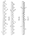
- the product, shown in Figure 15, is created by the same method as the product in Figure 14 except that at coating station B 106, slightly more of the prism formulation is applied to the tooling allowing the prisms in the areas between coating station A pattern coated areas to form air sphere prisms 120 providing the benefits described in U.S. Patent 5,592,330.
- Figure 16 is another variation of the product described in Figures 14 and 15.
- the pattern applied at coating station A 104 has a reduced amount of prism formulation 118 in the prism formulation applied at station B 106 is reduced to the level required to produce the matte finish in between the pattern area.
- the reduction of the prism formulation 118 at coating station A 104 causes air sphere prisms 120 co be formed in the pattern coated areas.
- Seamless material manufacturing can be used to produce retroreflective material which is includes air sphere configuration and defined areas in full solid corner cubed construction and other defined areas.
- a casting drum is covered with sufficient oligomer to create air sphere corner cubes 120 during the lamination process and the incoming substrate web is printed with a pattern of oligomer which when the pattern oligomer combines with the oligomer on the drum it creates solid corner cube prisms 64 in the pattern configuration printed on the substrate.
- This concept can be used to create any pattern of solid prisms 64 and air sphere prisms 120 desired.
- the combined air sphere corner cube and solid corner cube prisms provide a defined retroreflective light distribution with a solid comer cubed prisms providing excellent long distance performance (narrow observation angle) and short distance performance (wide observation angle).
- An example of this product construction flexibility is shown in Figure 17.
- the red oligomer is transparent and the difference in the retroreflectivity between an sphere and solid prism area creates enhanced contrast allowing an easy to read sign.
- the colored oligomer can be red in color for form a red area in a STOP sign.
- the surfaces of the prisms can be metalized 124.
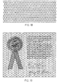
- Figure 18 shows a top view of the material with solid prism line pattern and air sphere prisms 120 in triangular areas.
- Figure 19 shows a photocopy of material with a message printed on top surface of clear substrate top film 112.
- the lines formed by solid prisms 64
- Such a retroreflective structure can be used to form security documents, such as stock certificates and the like. Further, portions of the document can have a series of long thin lines at portions which can in combination with the retroreflective structure form a moiré pattern when photocopied.
- Figure 20 is a produce construction which results if coating station A 104 is used to coat a transparent UV cured colored tie coat 126 across an entire web.
- Coating station B 106 is used co coat a sufficient amount of prism formulation to create air sphere prisms 120 across the entire web.
- the color is on the top layer of the prism and if a release coat were used between the top film and the tie coat, the color would end up on the top face of the free standing prisms created.
- Figure 21 is a product construction which results if coating station A 104 is used to coat a transparent colored prism formulation across an entire web.
- Coating station B 106 is used to coat sufficient prism formulation to create air sphere prisms 120 across the web.
- the transparent color 122 is in the prism and if a release coat were used between the top film 112 and the colored prism formulation, the color would end up within the structure of the free standing prisms created.
- Coating station A 104 applies to the top film 112 various thickness color coatings or prism formulations.
- Additional coating stations can be added in line at coating station A and at coating station B to create multiples of the color and prism shape effects desired. Also, when multiple prism forming systems are used, stripes around the circumference of the large drum in Figure 10 can be created by coating stripes at both coating stations A and B which are coincident with each other. When the material reaches a second drum, the areas between the stripes can be filled to create a filled surface on the top film. Prisms of different sizes or orientations can be applied at each prism forming station creating a parallel strip appearance on the top film. The spacing of the strips can be as small or large as desired.
Landscapes
- Engineering & Computer Science (AREA)
- Physics & Mathematics (AREA)
- Mechanical Engineering (AREA)
- Manufacturing & Machinery (AREA)
- General Physics & Mathematics (AREA)
- Optics & Photonics (AREA)
- Health & Medical Sciences (AREA)
- Ophthalmology & Optometry (AREA)
- Optical Elements Other Than Lenses (AREA)
- Laminated Bodies (AREA)
Description
Claims (29)
- An apparatus comprising: a coater (10) for producing visible patterns (20) on a transparent film (46), and prism forming apparatus (24) for applying transparent microprisms (64) onto said patterns, such that the patterns are viewable and protected from the environment by being incorporated into the microprisms and covered,by the film, the microprisms having a base (61) and side facets, wherein the printed patterns are embedded into the base of the microprisms.
- The apparatus of claim 1 wherein the facets are provided with a reflective backing (98) and the patterns are viewable from the base side.
- The apparatus of claim 2 wherein the film and microprisms are formed of the same material.
- The apparatus of claim 2 wherein the film and microprisms are formed of different material.
- The apparatus of claim 1 wherein the film patterns and microprisms are formed on a continuous roll.
- The apparatus of claim 1 further comprising:a first printer (10) for printing of said patterns on selected areas of a first side of said film;a first applicator (241) for applying a prism forming material to a first such mold surface (23) to at least partly fill the recesses with said material;a first mechanism (50) for transferring the material to the first side of the film to form first areas of arrays of prisms over the patterns leaving second areas of blank spaces on said first side of said film;a second applicator (241') for applying said prism forming material to a second such mold surface (23') to fill the recesses in the second mold surface with said material; anda second mechanism (50') for transferring the material in the recesses of the second mold surface onto the areas of blank spaces in the first side of the film in such a manner as to form a continuous film of sheeting with the patterns enclosed within the prisms on the first side of the film.
- '. The apparatus of claim 6 wherein the prismatic recesses in the first mold surface differ in size from those in the second mold surface.
- The apparatus of claim 6 wherein the areas of the spaces and areas of arrays on said mold surfaces are substantially equal and are alternately spaced over each of the mold surfaces.
- The apparatus of claim 6 wherein the selected areas of the printed patterns are located opposite both the first and second areas of arrays of prisms.
- The apparatus of claim 6 wherein the prism forming material and the pattern material are the same.
- A method of producing a patterned sheet (20) of retroreflective material comprising the steps of printing the patterns on a transparent film (46), applying microprisms (64) onto said patterns, such that the patterns are protected from the environment by being incorporated onto a window side (61) of the microprisms and covered by the film, the microprisms have a base (61) and side facets, wherein the patterns and microprisms are partly solidified as formed and after the microprisms are applied to the patterns and wherein the patterns and microprisms are solidified so that printed patterns are embedded into the base of the microprisms.
- The method of claim 11 wherein the microprisms are transparent and wherein the facets are provided with a reflective backing (98).
- The method of claim 12 wherein the film and microprisms are formed of the same material.
- The method of claim 12 wherein the film and microprisms are formed of different material.
- The method of claim 11 wherein the film is formed in a continuous roll.
- A method for printing patterns (20) of print material on microstructured optical sheeting (54) by forming a film (46) upon which an array of prisms (64) is formed comprising the steps of:printing said patterns on selected areas of a first side of said film;applying a prism forming material to a first mold surface having prismatic recesses (21) therein to at least partly fill the recesses with said material;transferring (50) the material to the first side of the film to form first areas of arrays of prisms over the patterns leaving second areas of blank spaces on said first side of the film;applying said prism forming material to a second mold surface (23') having prismatic recesses therein to at least partially fill the recesses in the second mold surface with said material; andtransferring the material (50') in the recesses of the second mold surface onto the areas of blank spaces in the first side of the film in such a manner as to form a continuous film of sheeting on the first side of the film, the prisms having a base (61) and side facets, wherein the patterns and prisms are partly solidified as formed and after the prisms are applied to the patterns and wherein the patterns and prisms are solidified so that printed patterns are embedded into the base of the prisms.
- The method of claim 16 wherein the prismatic recesses in the first mold surface differ in size from those in the second mold surface.
- The method of claim 16 wherein the areas of the spaces and areas of arrays on said mold surfaces are substantially equal and are alternately spaced over each of the mold surfaces.
- The method of claim 16 wherein the selected areas of the printed patterns are located opposite both the first and second areas of arrays of prisms.
- The method of claim 16 wherein the prism forming material and the pattern material are the same.
- The apparatus of claim 1 wherein a release coating (99) is formed between the film and the microprisms and patterns.
- The method of claim 16 wherein the optical sheeting is retroreflective sheeting.
- The method of claim 22 wherein some areas of the film have prism material directly attached to the film, and others have prism material covering the patterns and attached to the film and other areas have neither and can be used as sealing areas for attaching a sealing film over the sheeting.
- The method of claim 11, comprising the steps ofa) providing a mold surface (23) containing contiguous arrays of prismatic recesses;b) applying prism forming material to the selected areas of the arrays leaving other selected areas devoid of prism forming material;c) applying said transparent film (46) as a front film (46) to said mold surface and transferring the prism forming material from the mold to the front film leaving certain areas on the front film without prism forming material;d) solidifying (40) the prism material to form the microprism having a base (61) and side facets;e) applying a back film (95) over the areas of solidified prisms;f) sealing the front film to the back film at the said certain areas without prism forming material; andg) partially curing the printed patterns on the front film prior to transferring the prism forming material from the mold.
- The method of claim 24 wherein the mold surface is formed on the periphery of a circular rotary drum.
- Apparatus for printing patterns (20) of print material on retroreflective sheeting (54) formed of a film (46), said apparatus comprising a printer (10) and mold surfaces (23) containing areas of arrays of prismatic recesses (21) and areas of blank spaces, said apparatus including:a first printer (10) for printing of said patterns on selected areas of a first side of said film, some of said patterns comprising colored markings to improve the whiteness factor of the sheeting;a first applicator (24) for applying a prism forming material to a first portion of such mold surfaces to at least partly fill the recesses with said material; anda first mechanism (50) for transferring the prism forming material from the mold surfaces to the first side of the film to form first areas of arrays of prisms over the patterns leaving second areas of blank spaces on said first side of said film opposite the colored markings, wherein the patterns and prisms are partly solidified as formed and after the prisms are applied to the patterns and wherein the patterns and prisms are solidified so that printed patterns are embedded into some of the prisms.
- The apparatus of claim 26 wherein the markings are white dots or lines.
- The apparatus of claim 26 wherein the prism forming material and the print material are the same.
- A method for producing a patterned (20) sheet of microstructure optical sheeting (54) comprising the steps of printing the patterns on a first side of a transparent film (46) and applying the microstructures to said first side of said transparent film, the microstructures having a base and side facets, wherein the patterns and microstructures are partly solidified as formed and after the microstructures are applied to the patterns and wherein the patterns and microstructures are solidified so that printed patterns are embedded into the base of the microstructures.
Applications Claiming Priority (5)
| Application Number | Priority Date | Filing Date | Title |
|---|---|---|---|
| US13696 | 1979-02-21 | ||
| US09/013,696 US6119751A (en) | 1998-01-26 | 1998-01-26 | Apparatus and method for producing retroreflective material having printed patterns thereon |
| US09/170,014 US6120636A (en) | 1998-01-26 | 1998-10-13 | Apparatus and method for producing retroreflective material having printed patterns thereon |
| US170014 | 1998-10-13 | ||
| PCT/US1999/001644 WO1999037470A1 (en) | 1998-01-26 | 1999-01-26 | Retroreflective material having printed patterns thereon |
Publications (2)
| Publication Number | Publication Date |
|---|---|
| EP1051291A1 EP1051291A1 (en) | 2000-11-15 |
| EP1051291B1 true EP1051291B1 (en) | 2002-11-13 |
Family
ID=26685155
Family Applications (1)
| Application Number | Title | Priority Date | Filing Date |
|---|---|---|---|
| EP99902438A Expired - Lifetime EP1051291B1 (en) | 1998-01-26 | 1999-01-26 | Retroreflective material having printed patterns thereon |
Country Status (6)
| Country | Link |
|---|---|
| US (1) | US6120636A (en) |
| EP (1) | EP1051291B1 (en) |
| JP (1) | JP2002500969A (en) |
| CA (1) | CA2318039C (en) |
| DE (1) | DE69903917T2 (en) |
| WO (1) | WO1999037470A1 (en) |
Cited By (1)
| Publication number | Priority date | Publication date | Assignee | Title |
|---|---|---|---|---|
| CN107367779A (en) * | 2016-05-12 | 2017-11-21 | 三星显示有限公司 | Cap unit, the method for forming cap unit and the display device with cap unit |
Families Citing this family (63)
| Publication number | Priority date | Publication date | Assignee | Title |
|---|---|---|---|---|
| JP4063472B2 (en) † | 2000-04-10 | 2008-03-19 | 日本カーバイド工業株式会社 | Printed retroreflective sheet |
| US6130777A (en) * | 1996-05-16 | 2000-10-10 | Dai Nippon Printing Co., Ltd. | Lenticular lens sheet with both a base sheet having lenticular elements and a surface diffusing part having elements of elementary shape smaller than lenticular elements |
| US20050171478A1 (en) * | 1998-01-13 | 2005-08-04 | Selmon Matthew R. | Catheter system for crossing total occlusions in vasculature |
| US6227572B1 (en) * | 1999-03-01 | 2001-05-08 | Eric A. Lyen | Durable tactile indicia for banknotes/documents and method of making same |
| US7371465B2 (en) | 1999-03-30 | 2008-05-13 | Exxonmobil Oil Corporation | Polyolefin film with embossed surface |
| US6325515B1 (en) | 2000-03-21 | 2001-12-04 | 3M Innovative Properties Company | Cube corner retroreflective article with enhanced pigmentation |
| US6451373B1 (en) * | 2000-08-04 | 2002-09-17 | Advanced Cardiovascular Systems, Inc. | Method of forming a therapeutic coating onto a surface of an implantable prosthesis |
| JP3618292B2 (en) * | 2000-11-10 | 2005-02-09 | 日本カーバイド工業株式会社 | Retroreflective sheet with printed layer |
| FI20010084A0 (en) * | 2001-01-15 | 2001-01-15 | Metso Corp | Method and system for manufacturing optical elements and optical element |
| US6676869B2 (en) * | 2001-12-21 | 2004-01-13 | 3M Innovative Properties Company | Continuous process for indirect printing of polymeric films having texture |
| US20040043234A1 (en) * | 2002-05-10 | 2004-03-04 | Grant Hay | Light management films and articles thereof |
| DE10228013B4 (en) * | 2002-06-22 | 2005-11-03 | Hans-Erich Sen. Gubela | Partial transmission reflector, use of the partial transmission reflector and optical sensor system |
| ATE330056T1 (en) * | 2002-12-19 | 2006-07-15 | Ind Bergamasca Rifrangenti S R | METHOD FOR PRODUCING A PRINTED RETROREFLECTIVE MATERIAL |
| DE10307808B4 (en) * | 2003-02-24 | 2009-04-09 | Fer Fahrzeugelektrik Gmbh | Method for reducing the reflection value of a microprismatic reflective foil |
| US20060056031A1 (en) * | 2004-09-10 | 2006-03-16 | Capaldo Kevin P | Brightness enhancement film, and methods of making and using the same |
| EP2442147B1 (en) | 2003-03-06 | 2017-04-19 | 3M Innovative Properties Co. | Lamina comprising cube corner elements and retroreflective sheeting |
| US7152983B2 (en) | 2003-03-06 | 2006-12-26 | 3M Innovative Properties Company | Lamina comprising cube corner elements and retroreflective sheeting |
| US7527632B2 (en) * | 2003-03-31 | 2009-05-05 | Cordis Corporation | Modified delivery device for coated medical devices |
| EP1584738B1 (en) | 2004-04-01 | 2011-11-23 | Industria Bergamasca Rifrangenti S.r.l. | Method for producing a printed high-visibility product |
| US7329447B2 (en) * | 2004-04-01 | 2008-02-12 | 3M Innovative Properties Company | Retroreflective sheeting with controlled cap-Y |
| US20050232965A1 (en) * | 2004-04-15 | 2005-10-20 | Robert Falotico | Local administration of a combination of rapamycin and 17 beta-estradiol for the treatment of vulnerable plaque |
| KR100586406B1 (en) * | 2004-06-11 | 2006-06-08 | 김현대 | Cube corner type retroreflective device manufacturing method and retroreflective device |
| AT500617B1 (en) * | 2004-07-26 | 2006-02-15 | Fischer Gmbh | METHOD FOR DECORING SPORTS EQUIPMENT AND FILM FOR IMPLEMENTING THE PROCESS |
| US7341784B2 (en) * | 2004-09-10 | 2008-03-11 | General Electric Company | Light management film and its preparation and use |
| BRPI0500848A (en) * | 2005-01-10 | 2006-09-05 | Avery Dennison Do Brasil Ltda | film, substrate and film use |
| US20060263530A1 (en) * | 2005-05-19 | 2006-11-23 | General Electric Company | Process for making non-continuous articles with microstructures |
| US8177374B2 (en) * | 2005-06-16 | 2012-05-15 | Avery Dennison Corporation | Retroreflective sheet structure |
| US8506984B2 (en) | 2006-07-26 | 2013-08-13 | Cordis Corporation | Therapeutic agent elution control process |
| KR100840151B1 (en) | 2006-10-25 | 2008-06-23 | 미래나노텍(주) | Apparatus for manufacturing retroreflective film and method for manufacturing same |
| US8114248B2 (en) * | 2007-01-03 | 2012-02-14 | Asahi Kasei Kabushiki Kaisha | Roll-to-roll method and system for micro-replication of a pattern of large relief three-dimensional microstructures |
| US7976741B2 (en) * | 2007-02-12 | 2011-07-12 | Ichia Technologies, Inc. | Method of manufacturing light guide plate of keypad |
| US7609450B2 (en) * | 2007-03-29 | 2009-10-27 | Spartech Corporation | Plastic sheets with lenticular lens arrays |
| JP5600382B2 (en) * | 2007-05-07 | 2014-10-01 | ジェイディーエス ユニフェイズ コーポレーション | Structured surfaces that exhibit color by rotation |
| AU2008201903B2 (en) * | 2007-05-07 | 2013-03-28 | Viavi Solutions Inc. | Structured surfaces that exhibit color by rotation |
| US7547105B2 (en) | 2007-07-16 | 2009-06-16 | 3M Innovative Properties Company | Prismatic retroreflective article with cross-linked image layer and method of making same |
| US20090074831A1 (en) * | 2007-09-18 | 2009-03-19 | Robert Falotico | LOCAL VASCULAR DELIVERY OF mTOR INHIBITORS IN COMBINATION WITH PEROXISOME PROLIFERATORS-ACTIVATED RECEPTOR STIMULATORS |
| DE102007045412A1 (en) | 2007-09-21 | 2009-04-02 | Erich Utsch Ag | Illuminated sign arrangement for motor vehicle, has laminar expanded retro-reflecting layer arranged behind sign plate, where retro-reflecting layer and illuminating device are combined mechanically to illuminating module |
| US8420110B2 (en) | 2008-03-31 | 2013-04-16 | Cordis Corporation | Drug coated expandable devices |
| US8409601B2 (en) * | 2008-03-31 | 2013-04-02 | Cordis Corporation | Rapamycin coated expandable devices |
| TWI392898B (en) * | 2008-10-28 | 2013-04-11 | Suregiant Technology Co Ltd | An optical diaphragm manufacturing method and manufacturing apparatus thereof |
| EP2368147A4 (en) * | 2008-12-08 | 2018-01-24 | 3M Innovative Properties Company | Protective overlay bearing a graphic and retroreflective articles comprising the overlay |
| EP2361396A4 (en) * | 2008-12-08 | 2018-01-24 | 3M Innovative Properties Company | Prismatic retroreflective article bearing a graphic and method of making same |
| WO2010071956A1 (en) * | 2008-12-22 | 2010-07-01 | Canadian Bank Note Company, Limited | Improved printing of tactile marks for the visually impaired |
| BR112012007870A2 (en) | 2009-10-08 | 2020-08-18 | 3M Innovative Properties Company | retroreflective lamination, license plate and optical character recognition system |
| EP2499522A4 (en) * | 2009-11-12 | 2013-05-08 | 3M Innovative Properties Co | Security markings in retroreflective sheeting |
| WO2012102895A1 (en) * | 2011-01-25 | 2012-08-02 | Avery Dennison Corporation | A method for controlling retroreflectivity by application of a printed pattern to a retroreflective film and sheeting produced thereby |
| US8668340B2 (en) * | 2011-05-02 | 2014-03-11 | Jordan Danchov Jordanov | Reflective medical markers and methods of manufacture |
| EP2715414A4 (en) * | 2011-05-31 | 2014-12-31 | 3M Innovative Properties Co | CUBIC CORNER COATING HAVING AN OPTICALLY VARIABLE MARKING |
| US9523919B2 (en) | 2011-05-31 | 2016-12-20 | 3M Innovative Properties Company | Methods for making differentially pattern cured microstructured articles |
| WO2012166448A1 (en) * | 2011-05-31 | 2012-12-06 | 3M Innovative Properties Company | Retroreflective articles having composite cube-corners and methods of making |
| SG195166A1 (en) | 2011-05-31 | 2013-12-30 | 3M Innovative Properties Co | Method for making microstructured tools having discontinuous topographies, articles produced therefrom |
| KR102051832B1 (en) * | 2011-10-19 | 2019-12-04 | 애버리 데니슨 코포레이션 | Retroreflective sheeting having a halftone printed front surface |
| US9050762B2 (en) | 2012-03-23 | 2015-06-09 | Orafol Americas Inc. | Methods for fabricating retroreflector tooling and retroreflective microstructures and devices thereof |
| CA2868831A1 (en) | 2012-03-30 | 2013-10-03 | 3M Innovative Properties Company | Retroreflective articles having a machine-readable code |
| EP2724864B1 (en) * | 2012-10-24 | 2018-12-26 | Heidelberger Druckmaschinen AG | Method and device for creating and transferring diffractive microstructures on a printable material |
| DE202012011697U1 (en) * | 2012-12-06 | 2013-03-05 | Thomas Schäfer | Applicator for applying a material |
| US20150369975A1 (en) * | 2013-01-28 | 2015-12-24 | 3M Innovative Properties Company | Retroreflective sheeting having deformed cube corner elements |
| US10913234B2 (en) * | 2014-08-29 | 2021-02-09 | Clopay Plastic Products Company, Inc. | Embossed matte and glossy plastic film and methods of making same |
| US9324469B1 (en) * | 2014-10-31 | 2016-04-26 | Geraldine M. Hamilton | X-ray intensifying screens including micro-prism reflective layer for exposing X-ray film, X-ray film cassettes, and X-ray film assemblies |
| JP6301242B2 (en) * | 2014-11-28 | 2018-03-28 | 富士フイルム株式会社 | Infrared reflective pattern formation |
| JP6395576B2 (en) * | 2014-11-28 | 2018-09-26 | 富士フイルム株式会社 | Infrared reflective material, heat ray shielding material and window glass |
| US10551530B2 (en) | 2015-12-08 | 2020-02-04 | 3M Innovative Properties Company | Prismatic retroreflective sheeting including infrared absorbing material |
| US11220127B2 (en) | 2018-07-20 | 2022-01-11 | Griff And Associates, L.P. | Method and apparatus for roll-to-roll processing of sheet stock |
Family Cites Families (19)
| Publication number | Priority date | Publication date | Assignee | Title |
|---|---|---|---|---|
| US2143946A (en) * | 1935-05-30 | 1939-01-17 | Hunter Frederick | Method of manufacturing signs and other display devices |
| US2231139A (en) * | 1939-04-27 | 1941-02-11 | Gustave M Reininger | Reflective sign structure |
| US2422256A (en) * | 1940-02-13 | 1947-06-17 | Minnesota Mining & Mfg | Flexible reflex reflecting film |
| US2354049A (en) * | 1944-01-19 | 1944-07-18 | Minnesota Mining & Mfg | Backless reflex light reflector |
| US3689346A (en) * | 1970-09-29 | 1972-09-05 | Rowland Dev Corp | Method for producing retroreflective material |
| US4082426A (en) * | 1976-11-26 | 1978-04-04 | Minnesota Mining And Manufacturing Company | Retroreflective sheeting with retroreflective markings |
| US4202600A (en) * | 1978-04-24 | 1980-05-13 | Avery International Corporation | Diced retroreflective sheeting |
| MX169129B (en) * | 1984-08-10 | 1993-06-22 | Amerace Corp | METHOD FOR PRODUCING CONSTRUCTIONS OF RETRO-REFLECTIVE LAMINATED STRUCTURE SHEET OF THE TYPE OF CUBE CORNERS AND THE PRODUCT OBTAINED WITH THE SAME. |
| US4656072A (en) * | 1985-06-17 | 1987-04-07 | Coburn Corporation | Retroreflective material for providing a colored decorative effect in visible light |
| US4952023A (en) * | 1988-03-18 | 1990-08-28 | Minnesota Mining And Manufacturing Company | Internally illuminated retroreflective sign |
| US5262225A (en) * | 1988-09-02 | 1993-11-16 | Minnesota Mining And Manufacturing Company | Embossable sign construction |
| US5254390B1 (en) * | 1990-11-15 | 1999-05-18 | Minnesota Mining & Mfg | Plano-convex base sheet for retroreflective articles |
| US5213872A (en) * | 1991-04-19 | 1993-05-25 | Stimsonite Corporation | Preprinted retroreflective highway sign and method for making the sign |
| US5442870A (en) * | 1993-09-08 | 1995-08-22 | Kochanowski; George E. | Reflective sign |
| US5393590A (en) * | 1993-07-07 | 1995-02-28 | Minnesota Mining And Manufacturing Company | Hot stamping foil |
| WO1996003285A1 (en) * | 1994-07-26 | 1996-02-08 | Minnesota Mining And Manufacturing Company | Retroreflective graphic articles and thermal transfer articles |
| US5558740A (en) * | 1995-05-19 | 1996-09-24 | Reflexite Corporation | Method and apparatus for producing seamless retroreflective sheeting |
| US5592330A (en) * | 1995-05-19 | 1997-01-07 | Reflexite Corporation | Retroreflective prism arrays with formed air spheres therein |
| US5763049A (en) * | 1996-04-30 | 1998-06-09 | Minnesota Mining And Manufacturing Company | Formed ultra-flexible retroreflective cube-corner composite sheeting with target optical properties and method for making same |
-
1998
- 1998-10-13 US US09/170,014 patent/US6120636A/en not_active Expired - Lifetime
-
1999
- 1999-01-26 CA CA002318039A patent/CA2318039C/en not_active Expired - Fee Related
- 1999-01-26 DE DE69903917T patent/DE69903917T2/en not_active Expired - Lifetime
- 1999-01-26 WO PCT/US1999/001644 patent/WO1999037470A1/en not_active Ceased
- 1999-01-26 JP JP2000528423A patent/JP2002500969A/en active Pending
- 1999-01-26 EP EP99902438A patent/EP1051291B1/en not_active Expired - Lifetime
Cited By (3)
| Publication number | Priority date | Publication date | Assignee | Title |
|---|---|---|---|---|
| CN107367779A (en) * | 2016-05-12 | 2017-11-21 | 三星显示有限公司 | Cap unit, the method for forming cap unit and the display device with cap unit |
| CN107367779B (en) * | 2016-05-12 | 2022-03-25 | 三星显示有限公司 | Cover unit, method of forming cover unit, and display device having cover unit |
| EP3244257B1 (en) * | 2016-05-12 | 2024-07-31 | Samsung Display Co., Ltd. | Cover unit and display device having the same |
Also Published As
| Publication number | Publication date |
|---|---|
| CA2318039A1 (en) | 1999-07-29 |
| DE69903917D1 (en) | 2002-12-19 |
| WO1999037470A1 (en) | 1999-07-29 |
| JP2002500969A (en) | 2002-01-15 |
| EP1051291A1 (en) | 2000-11-15 |
| DE69903917T2 (en) | 2003-09-04 |
| US6120636A (en) | 2000-09-19 |
| CA2318039C (en) | 2007-08-21 |
Similar Documents
| Publication | Publication Date | Title |
|---|---|---|
| US6120636A (en) | Apparatus and method for producing retroreflective material having printed patterns thereon | |
| US6119751A (en) | Apparatus and method for producing retroreflective material having printed patterns thereon | |
| US5643400A (en) | Method and apparatus for producing seamless retroreflective sheeting | |
| US5254390A (en) | Plano-convex base sheet for retroreflective articles and method for making same | |
| US10562249B2 (en) | Cube corner retroreflective sheeting having channels | |
| US3935359A (en) | Retroreflective sheeting and method and apparatus for producing same | |
| EP1080383B1 (en) | Method of making a prefabricated retroreflective sign | |
| US5780140A (en) | Retroreflective microprismatic material with top face curvature and method of making same | |
| US8147075B2 (en) | Printed image-set retroreflective sheeting | |
| CN1192276A (en) | Retroreflective article having microprisms of various sizes at multiple locations | |
| KR20000065073A (en) | Shiny Cube Corner Objects | |
| US10509148B2 (en) | Irradiation marking of retroreflective sheeting | |
| KR20150111992A (en) | Retroreflective sheeting having deformed cube corner elements | |
| KR20020053873A (en) | Method of making signs having metalized cube corner sheeting | |
| HK1013863B (en) | Base sheet for retroreflective articles and method for making same | |
| HK1034576A (en) | Perforated retroreflective film |
Legal Events
| Date | Code | Title | Description |
|---|---|---|---|
| PUAI | Public reference made under article 153(3) epc to a published international application that has entered the european phase |
Free format text: ORIGINAL CODE: 0009012 |
|
| 17P | Request for examination filed |
Effective date: 20000804 |
|
| AK | Designated contracting states |
Kind code of ref document: A1 Designated state(s): DE FR GB |
|
| 17Q | First examination report despatched |
Effective date: 20010704 |
|
| GRAG | Despatch of communication of intention to grant |
Free format text: ORIGINAL CODE: EPIDOS AGRA |
|
| GRAG | Despatch of communication of intention to grant |
Free format text: ORIGINAL CODE: EPIDOS AGRA |
|
| GRAH | Despatch of communication of intention to grant a patent |
Free format text: ORIGINAL CODE: EPIDOS IGRA |
|
| GRAH | Despatch of communication of intention to grant a patent |
Free format text: ORIGINAL CODE: EPIDOS IGRA |
|
| GRAH | Despatch of communication of intention to grant a patent |
Free format text: ORIGINAL CODE: EPIDOS IGRA |
|
| GRAA | (expected) grant |
Free format text: ORIGINAL CODE: 0009210 |
|
| AK | Designated contracting states |
Kind code of ref document: B1 Designated state(s): DE FR GB |
|
| REG | Reference to a national code |
Ref country code: GB Ref legal event code: FG4D |
|
| REF | Corresponds to: |
Ref document number: 69903917 Country of ref document: DE Date of ref document: 20021219 |
|
| ET | Fr: translation filed | ||
| PLBE | No opposition filed within time limit |
Free format text: ORIGINAL CODE: 0009261 |
|
| STAA | Information on the status of an ep patent application or granted ep patent |
Free format text: STATUS: NO OPPOSITION FILED WITHIN TIME LIMIT |
|
| 26N | No opposition filed |
Effective date: 20030814 |
|
| REG | Reference to a national code |
Ref country code: DE Ref legal event code: R082 Ref document number: 69903917 Country of ref document: DE Representative=s name: PFENNING MEINIG & PARTNER GBR, DE Ref country code: DE Ref legal event code: R082 Ref document number: 69903917 Country of ref document: DE |
|
| REG | Reference to a national code |
Ref country code: DE Ref legal event code: R082 Ref document number: 69903917 Country of ref document: DE Representative=s name: PFENNING MEINIG & PARTNER GBR, DE Ref country code: DE Ref legal event code: R082 Ref document number: 69903917 Country of ref document: DE |
|
| REG | Reference to a national code |
Ref country code: DE Ref legal event code: R082 Ref document number: 69903917 Country of ref document: DE Representative=s name: PFENNING MEINIG & PARTNER GBR, DE Ref country code: DE Ref legal event code: R082 Ref document number: 69903917 Country of ref document: DE |
|
| REG | Reference to a national code |
Ref country code: FR Ref legal event code: CD Owner name: ORAFOL AMERICAS INC. Effective date: 20130521 |
|
| REG | Reference to a national code |
Ref country code: DE Ref legal event code: R082 Ref document number: 69903917 Country of ref document: DE Representative=s name: PFENNING, MEINIG & PARTNER MBB PATENTANWAELTE, DE Effective date: 20120418 Ref country code: DE Ref legal event code: R082 Ref document number: 69903917 Country of ref document: DE Representative=s name: PFENNING, MEINIG & PARTNER MBB PATENTANWAELTE, DE Effective date: 20130614 Ref country code: DE Ref legal event code: R082 Ref document number: 69903917 Country of ref document: DE Representative=s name: PFENNING, MEINIG & PARTNER MBB PATENTANWAELTE, DE Effective date: 20120628 Ref country code: DE Ref legal event code: R082 Ref document number: 69903917 Country of ref document: DE Representative=s name: PFENNING MEINIG & PARTNER GBR, DE Effective date: 20120418 Ref country code: DE Ref legal event code: R082 Ref document number: 69903917 Country of ref document: DE Representative=s name: PFENNING MEINIG & PARTNER GBR, DE Effective date: 20130614 Ref country code: DE Ref legal event code: R082 Ref document number: 69903917 Country of ref document: DE Representative=s name: PFENNING MEINIG & PARTNER GBR, DE Effective date: 20120628 Ref country code: DE Ref legal event code: R081 Ref document number: 69903917 Country of ref document: DE Owner name: ORAFOL AMERICAS INC., AVON, US Free format text: FORMER OWNER: REFLEXITE CORP., AVON, CONN., US Effective date: 20130722 Ref country code: DE Ref legal event code: R081 Ref document number: 69903917 Country of ref document: DE Owner name: ORAFOL AMERICAS INC., US Free format text: FORMER OWNER: REFLEXITE CORP., AVON, US Effective date: 20130722 |
|
| REG | Reference to a national code |
Ref country code: FR Ref legal event code: PLFP Year of fee payment: 18 |
|
| REG | Reference to a national code |
Ref country code: FR Ref legal event code: PLFP Year of fee payment: 19 |
|
| REG | Reference to a national code |
Ref country code: FR Ref legal event code: PLFP Year of fee payment: 20 |
|
| PGFP | Annual fee paid to national office [announced via postgrant information from national office to epo] |
Ref country code: DE Payment date: 20180122 Year of fee payment: 20 Ref country code: GB Payment date: 20180119 Year of fee payment: 20 |
|
| PGFP | Annual fee paid to national office [announced via postgrant information from national office to epo] |
Ref country code: FR Payment date: 20180119 Year of fee payment: 20 |
|
| REG | Reference to a national code |
Ref country code: DE Ref legal event code: R071 Ref document number: 69903917 Country of ref document: DE |
|
| REG | Reference to a national code |
Ref country code: GB Ref legal event code: PE20 Expiry date: 20190125 |
|
| PG25 | Lapsed in a contracting state [announced via postgrant information from national office to epo] |
Ref country code: GB Free format text: LAPSE BECAUSE OF EXPIRATION OF PROTECTION Effective date: 20190125 |