EP1050927A2 - Connection interface for position sensors - Google Patents
Connection interface for position sensors Download PDFInfo
- Publication number
- EP1050927A2 EP1050927A2 EP00109407A EP00109407A EP1050927A2 EP 1050927 A2 EP1050927 A2 EP 1050927A2 EP 00109407 A EP00109407 A EP 00109407A EP 00109407 A EP00109407 A EP 00109407A EP 1050927 A2 EP1050927 A2 EP 1050927A2
- Authority
- EP
- European Patent Office
- Prior art keywords
- interface
- connection
- housing
- connection interface
- sensor
- Prior art date
- Legal status (The legal status is an assumption and is not a legal conclusion. Google has not performed a legal analysis and makes no representation as to the accuracy of the status listed.)
- Withdrawn
Links
- 239000000463 material Substances 0.000 claims description 2
- 238000000465 moulding Methods 0.000 claims description 2
- 239000012780 transparent material Substances 0.000 claims description 2
- 230000011664 signaling Effects 0.000 description 4
- 238000004873 anchoring Methods 0.000 description 2
- 238000013037 co-molding Methods 0.000 description 2
- 238000009434 installation Methods 0.000 description 2
- 235000014676 Phragmites communis Nutrition 0.000 description 1
- 230000005540 biological transmission Effects 0.000 description 1
- 230000008878 coupling Effects 0.000 description 1
- 238000010168 coupling process Methods 0.000 description 1
- 238000005859 coupling reaction Methods 0.000 description 1
- 230000001419 dependent effect Effects 0.000 description 1
- 238000012423 maintenance Methods 0.000 description 1
- 239000007787 solid Substances 0.000 description 1
Images



Classifications
-
- G—PHYSICS
- G01—MEASURING; TESTING
- G01D—MEASURING NOT SPECIALLY ADAPTED FOR A SPECIFIC VARIABLE; ARRANGEMENTS FOR MEASURING TWO OR MORE VARIABLES NOT COVERED IN A SINGLE OTHER SUBCLASS; TARIFF METERING APPARATUS; MEASURING OR TESTING NOT OTHERWISE PROVIDED FOR
- G01D11/00—Component parts of measuring arrangements not specially adapted for a specific variable
- G01D11/30—Supports specially adapted for an instrument; Supports specially adapted for a set of instruments
-
- F—MECHANICAL ENGINEERING; LIGHTING; HEATING; WEAPONS; BLASTING
- F15—FLUID-PRESSURE ACTUATORS; HYDRAULICS OR PNEUMATICS IN GENERAL
- F15B—SYSTEMS ACTING BY MEANS OF FLUIDS IN GENERAL; FLUID-PRESSURE ACTUATORS, e.g. SERVOMOTORS; DETAILS OF FLUID-PRESSURE SYSTEMS, NOT OTHERWISE PROVIDED FOR
- F15B15/00—Fluid-actuated devices for displacing a member from one position to another; Gearing associated therewith
- F15B15/20—Other details, e.g. assembly with regulating devices
- F15B15/28—Means for indicating the position, e.g. end of stroke
- F15B15/2892—Means for indicating the position, e.g. end of stroke characterised by the attachment means
-
- G—PHYSICS
- G01—MEASURING; TESTING
- G01D—MEASURING NOT SPECIALLY ADAPTED FOR A SPECIFIC VARIABLE; ARRANGEMENTS FOR MEASURING TWO OR MORE VARIABLES NOT COVERED IN A SINGLE OTHER SUBCLASS; TARIFF METERING APPARATUS; MEASURING OR TESTING NOT OTHERWISE PROVIDED FOR
- G01D11/00—Component parts of measuring arrangements not specially adapted for a specific variable
- G01D11/24—Housings ; Casings for instruments
Definitions
- the present invention refers to a connection interface for position sensors for moving mechanical members, such as pneumatic and hydraulic cylinders and the like, and to a system comprising such interface.
- sensors have been developed and are currently used, from the simple sensors of the REED type to the more sophisticated ones with luminous signalling. These sensors, with different overall dimensions, have always been a problem for the users, due to these overall dimensions. For maintenance reasons, sensors have been created that are equipped with a connector, thereby increasing the dimensions still further, and generating other problems, such as criticalities of components when strong vibrations occur.
- the sensor with luminous LED is particularly useful when assembling and calibrating the cylinder, but also during operation.
- pneumatic and hydraulic cylinders are more and more made integral with the mechanical parts, and therefore the luminous signalling is not always visible. Particularly for pneumatic cylinders, but also for hydraulic cylinders, the trend is towards using small-sized sensors and for such purpose cylinders are being realised with particular outlines, suitable to house the new generation of sensors, the so-called "retractable" sensors.
- Object of the present invention is solving the above prior-art problems by providing a connection interface between sensor and connection cable.
- a further object of the present invention is providing an interface equipped with an integrated connector.
- a still further object of the present invention is providing an interface equipped with an anchoring system.
- a further object of the present invention is providing a connection interface equipped with luminous signalling that is visible from many sides, doing thereby without the display on sensors for the above-mentioned problems.
- connection interface and a system comprising such interface, as claimed in Claims 1 and 16.
- Preferred embodiments and nontrivial variations of the present invention are claimed in the dependent Claims.
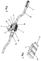
- connection interface 1 of the present invention is adapted to be connected to a position sensor 3 for moving mechanical members 5, such as pneumatic and hydraulic cylinders and the like.
- the interface 1 substantially comprises a support housing 7, in the embodiment shown having a box-like shape, made of plastic material and realised by co-molding in two parts, in order to allow its easy coupling when assembling the whole system.
- the housing 7 is equipped, by co-molding, with a plurality of windows 9 (two of which are shown in the Figures), made of transparent material, placed on at least two sides of the housing 7, to allow transmitting to the outside the light emitted by luminous displaying means (not shown, for example of the LED type) that are present inside the housing 7.
- Such LEDs are activated when a signal is present that is coming from the sensor 3, and the light emitted by them can thereby be easily viewed by an operator during installation or operation.
- the displaying means are controlled by a suitable control circuitry (placed inside the housing 7 and not shown in the drawings) that, among the different functions required by the application, controls the transmission of transducer signals towards external downstream devices, to perform the adequate actions.
- the interface 1 of the invention further comprises hooking means 11 connected to the housing 7; such hooking means allow securing the interface 1 to the supply pipe 13 of the cylinder 5, that is always present in every plant, usually in a number equal to two.
- hooking means 11 By using the pipe 13 as support (but in a similarly efficient way, it could be possible to secure the interface 1 to a wall or a place, obviously using adequate hooking means), an unmovable and safe positioning of the interface 1 is allowed, thereby avoiding the prior art problems of flying interfaces.
- the Figures show some embodiments of the hooking means 11, according to the application choices.
- the hooking means in a single piece with the housing 7, for example through molding, or it is possible to snappingly insert the hooking means 11 into the housing 7 by using suitable slits 15.
- the hooking means 11 it is obviously possible to secure the hooking means 11 to the housing 7 by using other common securing means, such as screws, rivets, etc.
- the hooking means 11 as half-ring-shaped snapping elements 17 (shown in Fig.s 1 to 5 and in detail in Fig. 7) that are adapted to be secured to the pipes 13, or as common hose clamps 19 (Fig. 6) with related closing block 21.
- the half-ring-shaped elements 17 of Fig. 7 are equipped on their top part with hooking teeth 22 for being secured to the respective slits 15 of the housing 7.
- the housing 7 is further equipped with a groove 23 with side stopping teeth 25 and with a groove 27 with side stopping teeth 29: such grooves 23 and 27 are adapted to house respective big 30 or small 31 identification plates (that can be coupled in series, as better shown in Fig. 5) to identify the interface 1 when installing it into the plant.
- the interface 1 further comprises input connection means (not shown) adapted to allow the connection of the interface 1 to the sensor 3; such input connection means are adapted to receive thereinto, in a fixed and unmovable way, an input cable 33, that in a first arrangement can be pre-wired when realising the interface 1; alternatively, the input connection means can be composed of a common connector (not shown) to be coupled with a similar connector of cable 33.
- the interface 1 comprises output connection means 35 adapted to allow the connection of the interface 1 to external devices; such output connection means 35 are adapted to receive thereinto, in a fixed and unmovable way, an output cable 37, that in a first arrangement can be pre-wired when realising the interface 1 (as shown in Fig.s 1 and 2); alternatively, the output connection means 35 can be composed of a common connector 38 to be coupled with a similar connector 39 for cable 37 (as shown in Fig.s 1 and 3-6).
- the major characteristic of the interface 1 of the invention is therefore that it is adapted, through hooking means 11, to be supported by supply pipes 13 of cylinder 5 to guarantee the sensor functionalities being provided in an easier way to be controlled, but in a similar "solid" way, outside the limited spaces that a plant of this type can have. Therefore, the invention provides the final realisation of a sensor system real and proper for moving mechanical members, such as pneumatic and hydraulic cylinders and the like, composed of the real sensor 3, of the input cable 33, of the above-described interface 1 and of the output cable 37, the whole system using the supply pipes 13, or other support means, for a more linear and efficient arrangement into the plant.
Landscapes
- Physics & Mathematics (AREA)
- General Physics & Mathematics (AREA)
- Engineering & Computer Science (AREA)
- Fluid Mechanics (AREA)
- Mechanical Engineering (AREA)
- General Engineering & Computer Science (AREA)
- Length Measuring Devices With Unspecified Measuring Means (AREA)
- Actuator (AREA)
Abstract
Description
- Figure 1 is a perspective view of an embodiment of a system with connection interface according to the present invention;
- Figure 2 is a perspective view of a particular variation of the interface in Fig. 1;
- Figure 3 is a perspective view of another particular variation of the interface in Fig. 1;
- Figure 4 is a perspective view of the interface in Fig. 3 with an identification plate assembled thereon;
- Figure 5 is an exploded perspective view of the interface in Fig. 3 pointing out other possible elementary identification plates;
- Figure 6 is a perspective view of an anchoring variation of the interface in Fig. 3; and
- Figure 7 is a perspective view of an embodiment of the hooking means of the interface of the invention.
Claims (16)
- Connection interface (1) for a position sensor (3) for moving mechanical members (5), such as pneumatic and hydraulic cylinders and the like, characterised in that it comprises:a support housing (7);hooking means (11) connected to said housing (7);luminous displaying means placed inside said housing (7) and adapted to be lighted when they receive a suitable signal from said sensor (3);a driving circuitry for said displaying means, said circuitry being placed inside said housing (7);input connection means adapted to allow the connection of said interface (1) to said sensor (3);output connection means (35) adapted to allow the connection of said interface (1) to external devices;said interface (1) being adapted, through said hooking means (11), to be supported by support means (13).
- Connection interface (1) according to Claim 1, characterised in that said support means (13) are composed of one of the supply pipes (13) of said moving mechanical member (5).
- Connection interface (1) according to Claim 1, characterised in that said support means are composed of a wall or a plane to which said interface (1) is secured.
- Connection interface (1) according to Claim 1, characterised in that said luminous displaying means are composed of at least one LED (Light Emitting Diode).
- Connection interface (1) according to Claim 1, characterised in that said housing (7) is made of plastic material and is co-molded with windows (9) made of transparent material adapted to allow transmitting to the outside the light emitted by said LED inside said housing.
- Connection interface (1) according to Claim 1, characterised in that said housing (7) is adapted to allow displaying the light emitted by said luminous displaying means at least from two of its sides through windows (9).
- Connection interface (1) according to Claim 1, characterised in that said hooking means (11) are made integrally with said housing (7) through molding.
- Connection interface (1) according to Claim 1, characterised in that said hooking means (11) are secured to said housing (7) through securing means (15, 22).
- Connection interface (1) according to Claim 1, characterised in that said hooking means (11) are composed of half-ring-shaped snapping elements (17) for different diameters of the pipe (13).
- Connection interface (1) according to Claim 1, characterised in that said hooking means (11) are composed of a hose clamp (19) with related closing block (21).
- Connection interface (1) according to Claim 1, characterised in that said input connection means and said output connection means (35) are adapted to receive thereinto a respective input cable (33) and a respective output cable (37) that are fixedly pre-wired therein.
- Connection interface (1) according to Claim 1, characterised in that said output connection means (35) are composed of a connector (38) to be coupled with a respective connector (39) of the output cable (37).
- Connection interface (1) according to Claim 1, characterised in that said input connection means are composed of a connector to be coupled with a respective connector of the input cable (33).
- Connection interface (1) according to Claim 1, characterised in that said interface (1) is further equipped with an identification plate (30) adapted to be housed into a groove (23) of said housing (7) and to be kept thereinto by stopping teeth (25).
- Connection interface (1) according to Claim 1, characterised in that said interface (1) is further equipped with a plurality of small identification plates (31) that can be coupled in series and are adapted to be housed into a groove (27) of said housing (7) and to be kept thereinto by stopping teeth (29).
- Connection system for position sensors (3) for moving mechanical members (5), comprising:at least one sensor (3);at least one interface (1) according to any one of the previous Claims, said interface (1) being equipped with at least one input cable (33), connected to said at least one sensor (3), and with at least one output cable (37) connected to external devices.
Applications Claiming Priority (2)
| Application Number | Priority Date | Filing Date | Title |
|---|---|---|---|
| IT99TO000368 IT1308474B1 (en) | 1999-05-07 | 1999-05-07 | CONNECTION INTERFACE FOR POSITION SENSORS FOR MOBILE ORGANIZATIONS, SUCH AS PNEUMATIC, HYDRAULIC AND SIMILAR CYLINDERS, AND |
| ITTO990368 | 1999-05-07 |
Publications (2)
| Publication Number | Publication Date |
|---|---|
| EP1050927A2 true EP1050927A2 (en) | 2000-11-08 |
| EP1050927A3 EP1050927A3 (en) | 2001-11-28 |
Family
ID=11417783
Family Applications (1)
| Application Number | Title | Priority Date | Filing Date |
|---|---|---|---|
| EP00109407A Withdrawn EP1050927A3 (en) | 1999-05-07 | 2000-05-03 | Connection interface for position sensors |
Country Status (2)
| Country | Link |
|---|---|
| EP (1) | EP1050927A3 (en) |
| IT (1) | IT1308474B1 (en) |
Family Cites Families (5)
| Publication number | Priority date | Publication date | Assignee | Title |
|---|---|---|---|---|
| US4383252A (en) * | 1980-11-24 | 1983-05-10 | Purcell Harold F | Intravenous drip feed monitor |
| FR2620530B1 (en) * | 1987-09-16 | 1991-04-12 | Celduc | ELECTRICAL SENSOR DEVICE |
| DE9312282U1 (en) * | 1993-08-17 | 1993-10-21 | Chou, Ming-Fu, Taichung | Measuring device for bicycles |
| US5885100A (en) * | 1997-05-12 | 1999-03-23 | Molex Incorporated | Electrical connector with light transmission means |
| DE29718934U1 (en) * | 1997-10-23 | 1997-12-11 | Sick AG, 79183 Waldkirch | Fastening device for sensors |
-
1999
- 1999-05-07 IT IT99TO000368 patent/IT1308474B1/en active
-
2000
- 2000-05-03 EP EP00109407A patent/EP1050927A3/en not_active Withdrawn
Also Published As
| Publication number | Publication date |
|---|---|
| EP1050927A3 (en) | 2001-11-28 |
| ITTO990368A1 (en) | 1999-08-07 |
| IT1308474B1 (en) | 2001-12-17 |
Similar Documents
| Publication | Publication Date | Title |
|---|---|---|
| US5268823A (en) | Light transmission apparatus for electro-optically coupling to a display panel for an electronic instrument | |
| EP1045453A3 (en) | LED array PCB with adhesive rod lens | |
| JP2009236972A (en) | Display device and manipulation device with light display | |
| WO2002048608A1 (en) | Surface light source system and optical deflection element | |
| EP2140755A3 (en) | Irrigation emitter unit | |
| DE502004000789D1 (en) | Hydrodynamic coupling arrangement with a coupling device inside the coupling housing | |
| US7143467B2 (en) | Vacuum cleaner with light guiding element | |
| US5198664A (en) | Photoelectric sensor assembly having compressible and sealing members | |
| ITSV960011A0 (en) | DIAPHRAGM PUMPING DEVICE. | |
| CN115439992A (en) | Aspirating Smoke Detector Units | |
| FR2814216B1 (en) | ORIENTATION DEVICE AND ON-BOARD ORIENTATION SYSTEM | |
| CN109099950A (en) | Proximity sensor | |
| ATE298046T1 (en) | VALVE-CONTROLLED FLUIDIC ACTUATOR ARRANGEMENT | |
| EP1050927A2 (en) | Connection interface for position sensors | |
| US7375976B2 (en) | Housing for communication apparatus capable of installing LED lamps having horizontal or vertical emitting direction therein, and communication apparatus comprising the same | |
| WO2007081928A2 (en) | 360 degree viewable light emitting apparatus | |
| ITTO911045A1 (en) | ANTI-VIBRATION FLEXIBLE CONDUIT WITH A FLAT CROSS SECTION. | |
| JP3639578B2 (en) | Linear drive | |
| JP2019027255A (en) | Watering equipment | |
| JP6915558B2 (en) | Door switch | |
| WO2015161997A1 (en) | Indication device for a power tool | |
| IT1273597B (en) | SINGLE CABLE FIBER BOARD SYSTEM WITH MULTIPLE MECHANICAL ADVANTAGE | |
| US5277622A (en) | Electric connecting device for pilot valves in a valve array | |
| US7352950B2 (en) | Lightpipe with multiple projections | |
| CN210801081U (en) | Slender microwave inductor |
Legal Events
| Date | Code | Title | Description |
|---|---|---|---|
| PUAI | Public reference made under article 153(3) epc to a published international application that has entered the european phase |
Free format text: ORIGINAL CODE: 0009012 |
|
| AK | Designated contracting states |
Kind code of ref document: A2 Designated state(s): AT BE CH CY DE DK ES FI FR GB GR IE IT LI LU MC NL PT SE |
|
| AX | Request for extension of the european patent |
Free format text: AL;LT;LV;MK;RO;SI |
|
| PUAL | Search report despatched |
Free format text: ORIGINAL CODE: 0009013 |
|
| AK | Designated contracting states |
Kind code of ref document: A3 Designated state(s): AT BE CH CY DE DK ES FI FR GB GR IE IT LI LU MC NL PT SE |
|
| AX | Request for extension of the european patent |
Free format text: AL;LT;LV;MK;RO;SI |
|
| RIC1 | Information provided on ipc code assigned before grant |
Free format text: 7H 01R 3/00 A, 7G 01D 11/24 B, 7G 01D 11/30 B, 7F 15B 15/28 B |
|
| AKX | Designation fees paid | ||
| REG | Reference to a national code |
Ref country code: DE Ref legal event code: 8566 |
|
| STAA | Information on the status of an ep patent application or granted ep patent |
Free format text: STATUS: THE APPLICATION IS DEEMED TO BE WITHDRAWN |
|
| 18D | Application deemed to be withdrawn |
Effective date: 20020529 |