EP1050876A1 - Device for curing a UV-curable resin layer applied to a main surface or between two disc elements of a disc-shaped registration carrier - Google Patents
Device for curing a UV-curable resin layer applied to a main surface or between two disc elements of a disc-shaped registration carrier Download PDFInfo
- Publication number
- EP1050876A1 EP1050876A1 EP00201613A EP00201613A EP1050876A1 EP 1050876 A1 EP1050876 A1 EP 1050876A1 EP 00201613 A EP00201613 A EP 00201613A EP 00201613 A EP00201613 A EP 00201613A EP 1050876 A1 EP1050876 A1 EP 1050876A1
- Authority
- EP
- European Patent Office
- Prior art keywords
- disc
- ultraviolet radiation
- radiation source
- registration carrier
- shaped registration
- Prior art date
- Legal status (The legal status is an assumption and is not a legal conclusion. Google has not performed a legal analysis and makes no representation as to the accuracy of the status listed.)
- Granted
Links
Images


Classifications
-
- B—PERFORMING OPERATIONS; TRANSPORTING
- B05—SPRAYING OR ATOMISING IN GENERAL; APPLYING FLUENT MATERIALS TO SURFACES, IN GENERAL
- B05D—PROCESSES FOR APPLYING FLUENT MATERIALS TO SURFACES, IN GENERAL
- B05D3/00—Pretreatment of surfaces to which liquids or other fluent materials are to be applied; After-treatment of applied coatings, e.g. intermediate treating of an applied coating preparatory to subsequent applications of liquids or other fluent materials
- B05D3/06—Pretreatment of surfaces to which liquids or other fluent materials are to be applied; After-treatment of applied coatings, e.g. intermediate treating of an applied coating preparatory to subsequent applications of liquids or other fluent materials by exposure to radiation
- B05D3/061—Pretreatment of surfaces to which liquids or other fluent materials are to be applied; After-treatment of applied coatings, e.g. intermediate treating of an applied coating preparatory to subsequent applications of liquids or other fluent materials by exposure to radiation using U.V.
- B05D3/065—After-treatment
- B05D3/067—Curing or cross-linking the coating
-
- B—PERFORMING OPERATIONS; TRANSPORTING
- B29—WORKING OF PLASTICS; WORKING OF SUBSTANCES IN A PLASTIC STATE IN GENERAL
- B29C—SHAPING OR JOINING OF PLASTICS; SHAPING OF MATERIAL IN A PLASTIC STATE, NOT OTHERWISE PROVIDED FOR; AFTER-TREATMENT OF THE SHAPED PRODUCTS, e.g. REPAIRING
- B29C35/00—Heating, cooling or curing, e.g. crosslinking or vulcanising; Apparatus therefor
- B29C35/02—Heating or curing, e.g. crosslinking or vulcanizing during moulding, e.g. in a mould
- B29C35/08—Heating or curing, e.g. crosslinking or vulcanizing during moulding, e.g. in a mould by wave energy or particle radiation
-
- F—MECHANICAL ENGINEERING; LIGHTING; HEATING; WEAPONS; BLASTING
- F26—DRYING
- F26B—DRYING SOLID MATERIALS OR OBJECTS BY REMOVING LIQUID THEREFROM
- F26B11/00—Machines or apparatus for drying solid materials or objects with movement which is non-progressive
- F26B11/18—Machines or apparatus for drying solid materials or objects with movement which is non-progressive on or in moving dishes, trays, pans, or other mainly-open receptacles
-
- F—MECHANICAL ENGINEERING; LIGHTING; HEATING; WEAPONS; BLASTING
- F26—DRYING
- F26B—DRYING SOLID MATERIALS OR OBJECTS BY REMOVING LIQUID THEREFROM
- F26B3/00—Drying solid materials or objects by processes involving the application of heat
- F26B3/28—Drying solid materials or objects by processes involving the application of heat by radiation, e.g. from the sun
-
- G—PHYSICS
- G11—INFORMATION STORAGE
- G11B—INFORMATION STORAGE BASED ON RELATIVE MOVEMENT BETWEEN RECORD CARRIER AND TRANSDUCER
- G11B7/00—Recording or reproducing by optical means, e.g. recording using a thermal beam of optical radiation by modifying optical properties or the physical structure, reproducing using an optical beam at lower power by sensing optical properties; Record carriers therefor
- G11B7/24—Record carriers characterised by shape, structure or physical properties, or by the selection of the material
- G11B7/26—Apparatus or processes specially adapted for the manufacture of record carriers
-
- B—PERFORMING OPERATIONS; TRANSPORTING
- B05—SPRAYING OR ATOMISING IN GENERAL; APPLYING FLUENT MATERIALS TO SURFACES, IN GENERAL
- B05D—PROCESSES FOR APPLYING FLUENT MATERIALS TO SURFACES, IN GENERAL
- B05D1/00—Processes for applying liquids or other fluent materials
- B05D1/002—Processes for applying liquids or other fluent materials the substrate being rotated
-
- B—PERFORMING OPERATIONS; TRANSPORTING
- B29—WORKING OF PLASTICS; WORKING OF SUBSTANCES IN A PLASTIC STATE IN GENERAL
- B29C—SHAPING OR JOINING OF PLASTICS; SHAPING OF MATERIAL IN A PLASTIC STATE, NOT OTHERWISE PROVIDED FOR; AFTER-TREATMENT OF THE SHAPED PRODUCTS, e.g. REPAIRING
- B29C35/00—Heating, cooling or curing, e.g. crosslinking or vulcanising; Apparatus therefor
- B29C35/02—Heating or curing, e.g. crosslinking or vulcanizing during moulding, e.g. in a mould
- B29C35/08—Heating or curing, e.g. crosslinking or vulcanizing during moulding, e.g. in a mould by wave energy or particle radiation
- B29C35/0805—Heating or curing, e.g. crosslinking or vulcanizing during moulding, e.g. in a mould by wave energy or particle radiation using electromagnetic radiation
- B29C2035/0827—Heating or curing, e.g. crosslinking or vulcanizing during moulding, e.g. in a mould by wave energy or particle radiation using electromagnetic radiation using UV radiation
-
- B—PERFORMING OPERATIONS; TRANSPORTING
- B29—WORKING OF PLASTICS; WORKING OF SUBSTANCES IN A PLASTIC STATE IN GENERAL
- B29C—SHAPING OR JOINING OF PLASTICS; SHAPING OF MATERIAL IN A PLASTIC STATE, NOT OTHERWISE PROVIDED FOR; AFTER-TREATMENT OF THE SHAPED PRODUCTS, e.g. REPAIRING
- B29C65/00—Joining or sealing of preformed parts, e.g. welding of plastics materials; Apparatus therefor
- B29C65/48—Joining or sealing of preformed parts, e.g. welding of plastics materials; Apparatus therefor using adhesives, i.e. using supplementary joining material; solvent bonding
-
- B—PERFORMING OPERATIONS; TRANSPORTING
- B29—WORKING OF PLASTICS; WORKING OF SUBSTANCES IN A PLASTIC STATE IN GENERAL
- B29C—SHAPING OR JOINING OF PLASTICS; SHAPING OF MATERIAL IN A PLASTIC STATE, NOT OTHERWISE PROVIDED FOR; AFTER-TREATMENT OF THE SHAPED PRODUCTS, e.g. REPAIRING
- B29C65/00—Joining or sealing of preformed parts, e.g. welding of plastics materials; Apparatus therefor
- B29C65/48—Joining or sealing of preformed parts, e.g. welding of plastics materials; Apparatus therefor using adhesives, i.e. using supplementary joining material; solvent bonding
- B29C65/4805—Joining or sealing of preformed parts, e.g. welding of plastics materials; Apparatus therefor using adhesives, i.e. using supplementary joining material; solvent bonding characterised by the type of adhesives
- B29C65/483—Reactive adhesives, e.g. chemically curing adhesives
- B29C65/4845—Radiation curing adhesives, e.g. UV light curing adhesives
-
- B—PERFORMING OPERATIONS; TRANSPORTING
- B29—WORKING OF PLASTICS; WORKING OF SUBSTANCES IN A PLASTIC STATE IN GENERAL
- B29C—SHAPING OR JOINING OF PLASTICS; SHAPING OF MATERIAL IN A PLASTIC STATE, NOT OTHERWISE PROVIDED FOR; AFTER-TREATMENT OF THE SHAPED PRODUCTS, e.g. REPAIRING
- B29C66/00—General aspects of processes or apparatus for joining preformed parts
- B29C66/40—General aspects of joining substantially flat articles, e.g. plates, sheets or web-like materials; Making flat seams in tubular or hollow articles; Joining single elements to substantially flat surfaces
- B29C66/41—Joining substantially flat articles ; Making flat seams in tubular or hollow articles
- B29C66/45—Joining of substantially the whole surface of the articles
-
- B—PERFORMING OPERATIONS; TRANSPORTING
- B29—WORKING OF PLASTICS; WORKING OF SUBSTANCES IN A PLASTIC STATE IN GENERAL
- B29L—INDEXING SCHEME ASSOCIATED WITH SUBCLASS B29C, RELATING TO PARTICULAR ARTICLES
- B29L2009/00—Layered products
-
- B—PERFORMING OPERATIONS; TRANSPORTING
- B29—WORKING OF PLASTICS; WORKING OF SUBSTANCES IN A PLASTIC STATE IN GENERAL
- B29L—INDEXING SCHEME ASSOCIATED WITH SUBCLASS B29C, RELATING TO PARTICULAR ARTICLES
- B29L2017/00—Carriers for sound or information
- B29L2017/001—Carriers of records containing fine grooves or impressions, e.g. disc records for needle playback, cylinder records
- B29L2017/003—Records or discs
Definitions
- the invention relates to a device for curing a UV-curable resin layer applied to a main surface or between two disc elements of a disc-shaped registration carrier, comprising rotation means for supporting the disc-shaped registration carrier and rotating it in a plane, and a rectilinear ultraviolet radiation source which is radially disposed with respect to the disc-shaped registration carrier for emitting ultraviolet radiation to the UV-curable resin layer, wherein the length and the position of the rectilinear ultraviolet radiation source are such that the rectilinear radiation source is disposed opposite the disc-shaped registration carrier from a distance from the centre of the disc-shaped registration carrier to the edge thereof.
- a device of this kind may be considered to be known, as is indicated in passing in European patent No. 0 574 975.
- the rectilinear ultraviolet radiation source is disposed parallel to the aforesaid plane, as a result of which the UV-curable resin layer is unevenly exposed by the ultraviolet radiation from the rectilinear ultraviolet radiation source.
- the object of the present invention is to provide an even exposure of the UV-curable resin layer.
- the invention provides a device of the kind referred to in the introduction, which is characterized in that the rectilinear ultraviolet radiation source is disposed at an angle of between 0 and 90 degrees to the aforesaid plane.
- a model has been developed on the basis of which an optimum angle can be determined, depending on the position of the rectilinear ultraviolet radiation source with respect to the aforesaid plane and the length of the rectilinear ultraviolet radiation source.
- This model for ultraviolet radiation energy as a function of the radius of the disc-shaped registration carrier has been verified by measurement of the unevenness in the intensity of the ultraviolet radiation over the radius of the disc-shaped registration carrier, whereby it has become apparent that this model is satisfactory in practice. It has appeared in particular that the optimum angle ranges between 20 degrees and 70 degrees, depending on the length of the rectilinear ultraviolet radiation source.
- Another object of the invention is to eliminate the need to use the aforesaid additional reflectors, partially because they are subject to fouling, and in order to accomplish that objective the invention provides this further aspect that the rectilinear ultraviolet radiation source is disposed opposite the disc-shaped registration carrier in such a manner that it extends beyond the edge of said disc-shaped registration carrier.
- the device which is known from the aforesaid European patent No. 0 574 975 is capable of providing even exposure of a UV-curable resin layer applied to a main surface of a disc-shaped registration carrier whilst at the same time exposing of a UV-curable resin layer applied to the edge surface of the disc-shaped registration carrier,
- a tubular ultraviolet radiation source is disposed at an angle of 90 degrees to the aforesaid plane, and a revolution body reflector is provided, on the central axis of which the tubular ultraviolet radiation source is positioned.
- This arrangement of the prior art device results in a low dose of ultraviolet radiation, since the larger part of the radiation is indirect radiation.
- the portion of ultraviolet radiation that has a wavelength of less than 250 nm is too small.
- the reflection from the reflector is about 80% for UV-A/B and about 40% for UV-C.
- UV-C is important in particular for curing the UV-curable resin layer applied to the main surface of the disc-shaped registration carrier. The low dose renders it impossible to reduce the cycle time, thus necessitating the use of a tubular ultraviolet radiation source having a greater capacity, as a result of which the heat input is large.
- One embodiment of the invention for increasing the light intensity is characterized in that a reflector is disposed parallel to the side of the rectilinear ultraviolet radiation source that faces away from the disc-shaped registration carrier.
- one embodiment of the invention is characterized in that the rectilinear ultraviolet radiation source is provided with a reflector on the side that faces away from the disc-shaped registration carrier.
- This reflector may consist of a coating which is present on part of the rectilinear ultraviolet radiation source.
- the reflector is a cold light reflector, which transmits heat radiation.
- the essence of the present invention is to provide a linear ultraviolet radiation source which is disposed at such an angle that uniform exposure will take place upon rotation of the disc-shaped registration carrier to be exposed. Since the minimum energy remains practically constant, the capacity of the rectilinear ultraviolet radiation source does not need to be higher than in the conventional case, wherein the rectilinear ultraviolet radiation source is positioned parallel to the disc-shaped registration carrier.
- the UV-curable resin layer applied to a main surface of a disc-shaped registration carrier may be a protective coating, and the registration carrier of the CD-type.
- the UV-curable resin layer applied between two disc elements of a disc-shaped registration carrier is a bonding, adhesive or glue layer for joining said disc elements at the time of UV-curing.
- the registration carrier may be of the DVD-type or SACD-type.
- the DVD-type registration carrier may have more than two disc elements and more than one UV-curable resin (bonding) layer (DVD 18, for instance).
- the UV-curable resin layer may be applied as disclosed in, for example, WO 97/36737 or DE-A1-40 41 199.
- rotation means 1 support a disc-shaped registration carrier 2 for rotating the disc-shaped registration carrier 2 in a plane indicated by line A.
- a UV-curable resin layer 5, which is to be cured by means of ultraviolet radiation, is present on a main surface 3 of the disc-shaped registration carrier 2 (of CD-type, for instance).
- a rectilinear ultraviolet radiation source 7 for emitting ultraviolet radiation to UV-curable resin layer 5 is disposed radially with respect to the disc-shaped registration carrier 2.
- the length of the rectilinear ultraviolet radiation source 7, which is indicated at L LAMP in Figure 1, and the position of the rectilinear ultraviolet radiation source 7 are such that the rectilinear ultraviolet radiation source 7 is disposed opposite the disc-shaped registration carrier 2 from a distance r LAMP from the centre of the disc-shaped registration carrier 2 defined by the central axis which is indicated at C in Figure 1 to the edge of the disc-shaped registration carrier 2 which is indicated at R DISC in Figure 1.
- the rectilinear ultraviolet radiation source 7 is disposed at an angle of between 0 and 90 degrees to plane A, which angle is indicated at ⁇ in Figure 1.
- the rectilinear ultraviolet radiation source 7 is disposed opposite the disc-shaped registration carrier in such a manner that it extends beyond the edge R DISC of the disc-shaped registration carrier 2.
- P indicates the so-called starting point of the rectilinear ultraviolet radiation source 7
- h indicates the so-called initial height of the rectilinear ultraviolet radiation source 7
- R LAMP indicates the distance from the starting point P of the rectilinear ultraviolet radiation source 7 to the central axis C.
- the initial height h of the rectilinear ultraviolet radiation source 7 is the distance from the UV-curable resin layer 5 to be cured to starting point P of the rectilinear ultraviolet radiation source 7 at R LAMP .
- the initial height h may be a negative height.
- r LAMP , R DISC and R LAMP will also be called the end radius, the disc radius and the starting radius, respectively, and a will be called the angle of inclination.
- a UV-curable resin layer indicated at 9 in Figure 1 which is present on the edge surface of the disc-shaped registration carrier 2 indicated at 8 in Figure 1, will be exposed by the rectilinear ultraviolet radiation source 7 at the same time as the UV-curable resin layer 5.
- a reflector 10 is disposed parallel to a side of the rectilinear ultraviolet radiation source 7 that faces away from the disc-shaped registration carrier 2, which reflector may be a parabolic reflector and which is preferably a cold light reflector.
- reflector 10 is present on the rectilinear ultraviolet radiation source 7, for example in the form of a coating.
- L LAMP , ⁇ and P are variables.
- an embodiment of the device according to the invention (not shown) comprises means for adjusting the angle of inclination ⁇ .
- the rectilinear ultraviolet radiation source 7 may be a radiation source which produces deeper ultraviolet radiation, in particular ultraviolet radiation of up to approximately 180 nm.
- Figure 4 is analogous to Figure 1.
- Figure 4 differs from Figure 1 in that a UV-curable resin layer 5 to be cured is present between two disc elements 21, 22 of a disc-shaped registration carrier 2 (of DVD-type or SACD-type, for instance).
- Said UV-curable resin layer 5 in this case is for joining or bonding disc elements 21, 22 to result in a unitary registration carrier 2.
- Radiation source 7 in operation radiates UV-radiation to the UV-curable resin layer 5 through disc element 21.
Landscapes
- Engineering & Computer Science (AREA)
- Health & Medical Sciences (AREA)
- Mechanical Engineering (AREA)
- General Engineering & Computer Science (AREA)
- Physics & Mathematics (AREA)
- Manufacturing & Machinery (AREA)
- Oral & Maxillofacial Surgery (AREA)
- Toxicology (AREA)
- Plasma & Fusion (AREA)
- Thermal Sciences (AREA)
- Life Sciences & Earth Sciences (AREA)
- Microbiology (AREA)
- Manufacturing Optical Record Carriers (AREA)
- Application Of Or Painting With Fluid Materials (AREA)
- Laminated Bodies (AREA)
- Shaping Of Tube Ends By Bending Or Straightening (AREA)
- Optical Record Carriers And Manufacture Thereof (AREA)
- Heating, Cooling, Or Curing Plastics Or The Like In General (AREA)
Abstract
Description
- Device for curing a UV-curable resin layer applied to a main surface or between two disc elements of a disc-shaped registration carrier.
- The invention relates to a device for curing a UV-curable resin layer applied to a main surface or between two disc elements of a disc-shaped registration carrier, comprising rotation means for supporting the disc-shaped registration carrier and rotating it in a plane, and a rectilinear ultraviolet radiation source which is radially disposed with respect to the disc-shaped registration carrier for emitting ultraviolet radiation to the UV-curable resin layer, wherein the length and the position of the rectilinear ultraviolet radiation source are such that the rectilinear radiation source is disposed opposite the disc-shaped registration carrier from a distance from the centre of the disc-shaped registration carrier to the edge thereof.
- A device of this kind may be considered to be known, as is indicated in passing in European patent No. 0 574 975.
- In the prior art device the rectilinear ultraviolet radiation source is disposed parallel to the aforesaid plane, as a result of which the UV-curable resin layer is unevenly exposed by the ultraviolet radiation from the rectilinear ultraviolet radiation source.
- The object of the present invention is to provide an even exposure of the UV-curable resin layer.
- In order to accomplish that objective, the invention provides a device of the kind referred to in the introduction, which is characterized in that the rectilinear ultraviolet radiation source is disposed at an angle of between 0 and 90 degrees to the aforesaid plane.
- A model has been developed on the basis of which an optimum angle can be determined, depending on the position of the rectilinear ultraviolet radiation source with respect to the aforesaid plane and the length of the rectilinear ultraviolet radiation source. This model for ultraviolet radiation energy as a function of the radius of the disc-shaped registration carrier has been verified by measurement of the unevenness in the intensity of the ultraviolet radiation over the radius of the disc-shaped registration carrier, whereby it has become apparent that this model is satisfactory in practice. It has appeared in particular that the optimum angle ranges between 20 degrees and 70 degrees, depending on the length of the rectilinear ultraviolet radiation source.
- It is also possible to determine the optimum angle empirically, of course, whereby means may be provided for adjusting the said angle.
- In the prior art device, additional reflectors are required for assisting in the curing of a UV-curable resin layer applied to the edge surface of the disc-shaped registration carrier. In this connection reference is also made to German patent No. 195 45 943.
- Another object of the invention is to eliminate the need to use the aforesaid additional reflectors, partially because they are subject to fouling, and in order to accomplish that objective the invention provides this further aspect that the rectilinear ultraviolet radiation source is disposed opposite the disc-shaped registration carrier in such a manner that it extends beyond the edge of said disc-shaped registration carrier.
- It is noted that also the device which is known from the aforesaid European patent No. 0 574 975 is capable of providing even exposure of a UV-curable resin layer applied to a main surface of a disc-shaped registration carrier whilst at the same time exposing of a UV-curable resin layer applied to the edge surface of the disc-shaped registration carrier, In this prior art device, however, a tubular ultraviolet radiation source is disposed at an angle of 90 degrees to the aforesaid plane, and a revolution body reflector is provided, on the central axis of which the tubular ultraviolet radiation source is positioned. This arrangement of the prior art device results in a low dose of ultraviolet radiation, since the larger part of the radiation is indirect radiation. In particular the portion of ultraviolet radiation that has a wavelength of less than 250 nm is too small. The reflection from the reflector is about 80% for UV-A/B and about 40% for UV-C. UV-C is important in particular for curing the UV-curable resin layer applied to the main surface of the disc-shaped registration carrier. The low dose renders it impossible to reduce the cycle time, thus necessitating the use of a tubular ultraviolet radiation source having a greater capacity, as a result of which the heat input is large.
- One embodiment of the invention for increasing the light intensity is characterized in that a reflector is disposed parallel to the side of the rectilinear ultraviolet radiation source that faces away from the disc-shaped registration carrier.
- In order to eliminate the phenomenon of reflector fouling, one embodiment of the invention is characterized in that the rectilinear ultraviolet radiation source is provided with a reflector on the side that faces away from the disc-shaped registration carrier. This reflector may consist of a coating which is present on part of the rectilinear ultraviolet radiation source. When this rectilinear ultraviolet radiation source is replaced, a new reflector becomes available again.
- Preferably, the reflector is a cold light reflector, which transmits heat radiation.
- As a result of the direct exposure in accordance with the present invention a higher ultraviolet radiation efficiency is realised, which makes it possible to use a rectilinear ultraviolet radiation source which produces deeper ultraviolet radiation, in particular up to approximately 180 nm. The present invention allows a reduction of the cycle time. Cycle times of less than two seconds are attainable.
- The essence of the present invention is to provide a linear ultraviolet radiation source which is disposed at such an angle that uniform exposure will take place upon rotation of the disc-shaped registration carrier to be exposed. Since the minimum energy remains practically constant, the capacity of the rectilinear ultraviolet radiation source does not need to be higher than in the conventional case, wherein the rectilinear ultraviolet radiation source is positioned parallel to the disc-shaped registration carrier.
- The UV-curable resin layer applied to a main surface of a disc-shaped registration carrier may be a protective coating, and the registration carrier of the CD-type.
- The UV-curable resin layer applied between two disc elements of a disc-shaped registration carrier is a bonding, adhesive or glue layer for joining said disc elements at the time of UV-curing. The registration carrier may be of the DVD-type or SACD-type. The DVD-type registration carrier may have more than two disc elements and more than one UV-curable resin (bonding) layer (DVD 18, for instance). The UV-curable resin layer may be applied as disclosed in, for example, WO 97/36737 or DE-A1-40 41 199.
- The invention will now be described in more detail with reference to the drawings, wherein:
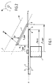
- Figure 1 is a schematic representation of an embodiment of the device according to the invention;
- Figure 2 is a sectional view of the ultraviolet radiation source and parabolic reflector of Figure 1;
- Figure 3 is a graph which shows the unevenness in the dose as a function of the angle of inclination α with different values of the length LLAMP of the rectilinear ultraviolet radiation source; and
- Figure 4 is a schematic representation of another embodiment of the device according to the invention.
-
- In Figure 1, rotation means 1 support a disc-
shaped registration carrier 2 for rotating the disc-shaped registration carrier 2 in a plane indicated by line A. A UV-curable resin layer 5, which is to be cured by means of ultraviolet radiation, is present on a main surface 3 of the disc-shaped registration carrier 2 (of CD-type, for instance). A rectilinear ultraviolet radiation source 7 for emitting ultraviolet radiation to UV-curable resin layer 5 is disposed radially with respect to the disc-shaped registration carrier 2. The length of the rectilinear ultraviolet radiation source 7, which is indicated at LLAMP in Figure 1, and the position of the rectilinear ultraviolet radiation source 7 are such that the rectilinear ultraviolet radiation source 7 is disposed opposite the disc-shaped registration carrier 2 from a distance rLAMP from the centre of the disc-shaped registration carrier 2 defined by the central axis which is indicated at C in Figure 1 to the edge of the disc-shaped registration carrier 2 which is indicated at RDISC in Figure 1. The rectilinear ultraviolet radiation source 7 is disposed at an angle of between 0 and 90 degrees to plane A, which angle is indicated at α in Figure 1. - In the embodiment which is shown in Figure 1, the rectilinear ultraviolet radiation source 7 is disposed opposite the disc-shaped registration carrier in such a manner that it extends beyond the edge RDISC of the disc-
shaped registration carrier 2. In Figure 1, P indicates the so-called starting point of the rectilinear ultraviolet radiation source 7, and h indicates the so-called initial height of the rectilinear ultraviolet radiation source 7, whilst RLAMP indicates the distance from the starting point P of the rectilinear ultraviolet radiation source 7 to the central axis C. The initial height h of the rectilinear ultraviolet radiation source 7 is the distance from the UV-curable resin layer 5 to be cured to starting point P of the rectilinear ultraviolet radiation source 7 at RLAMP. The initial height h may be a negative height. rLAMP, RDISC and RLAMP will also be called the end radius, the disc radius and the starting radius, respectively, and a will be called the angle of inclination. - When the rectilinear ultraviolet radiation source 7 extends beyond the disc radius, a UV-curable resin layer indicated at 9 in Figure 1, which is present on the edge surface of the disc-
shaped registration carrier 2 indicated at 8 in Figure 1, will be exposed by the rectilinear ultraviolet radiation source 7 at the same time as the UV-curable resin layer 5. - As is shown in Figures 1 and 2, a
reflector 10 is disposed parallel to a side of the rectilinear ultraviolet radiation source 7 that faces away from the disc-shaped registration carrier 2, which reflector may be a parabolic reflector and which is preferably a cold light reflector. Advantageously, albeit not shown in the figures,reflector 10 is present on the rectilinear ultraviolet radiation source 7, for example in the form of a coating. - A model has been drawn up for the exposure energy as a function of the radius of the disc-
shaped registration carrier 2. In said model, LLAMP, α and P (RLAMP, h) are variables. The results expressed as unevenness (difference between maximum and minimum values) in intensity over the radius of the disc-shaped registration carrier 2, when the disc-shaped registration carrier 2 has completed one revolution, as a function of α are represented in Figure 3 for variations in LLAMP in the case that RLAMP = 7.5 cm and h = 2 cm. - It can be concluded from Figure 3 that the angle of inclination α must range between 20 and 70 degrees when the required unevenness is to be below 20%.
- Since the optimum angle of inclination α is a function of LLAMP and P, it may be advantageous for angle of inclination α to be adjustable. To that end an embodiment of the device according to the invention (not shown) comprises means for adjusting the angle of inclination α.
- The rectilinear ultraviolet radiation source 7 may be a radiation source which produces deeper ultraviolet radiation, in particular ultraviolet radiation of up to approximately 180 nm.
- Figure 4 is analogous to Figure 1. For matter already discussed in regard of Figure 1 the same reference symbols are used in Figure 1. Figure 4 differs from Figure 1 in that a UV-
curable resin layer 5 to be cured is present between twodisc elements curable resin layer 5 in this case is for joining or bondingdisc elements unitary registration carrier 2. Radiation source 7 in operation radiates UV-radiation to the UV-curable resin layer 5 throughdisc element 21.
Claims (9)
- A device for curing a UV-curable resin layer applied to a main surface or between two disc elements of a disc-shaped registration carrier, comprising rotation means for supporting the disc-shaped registration carrier and rotating it in a plane, and a rectilinear ultraviolet radiation source which is radially disposed with respect to the disc-shaped registration carrier for emitting ultraviolet radiation to the UV-curable resin layer, wherein the length and the position of the rectilinear ultraviolet radiation source are such that the rectilinear radiation source is disposed opposite the disc-shaped registration carrier from a distance from the centre of the disc-shaped registration carrier to the edge thereof, characterized in that the rectilinear ultraviolet radiation source is disposed at an angle of between 0 and 90 degrees to the aforesaid plane.
- A device according to claim 1, characterized in that said angle ranges between 20 and 70 degrees.
- A device according to claim 1 or 2, characterized in that said device furthermore comprises means for adjusting said angle.
- A device according to any one of the preceding claims, characterized in that the rectilinear ultraviolet radiation source is disposed opposite the disc-shaped registration carrier in such a manner that it extends beyond the edge of said disc-shaped registration carrier.
- A device according to any one of the preceding claims, characterized in that a reflector is disposed parallel to the side of the rectilinear ultraviolet radiation source that faces away from the disc-shaped registration carrier.
- A device according to any one of the claims 1 - 4, characterized in that the rectilinear ultraviolet radiation source is provided with a reflector on the side that faces away from the disc-shaped registration carrier.
- A device according to claim 5 or 6, characterized in that the reflector is a cold light reflector.
- A device according to any one of the preceding claims, characterized in that the rectilinear ultraviolet radiation source produces deeper ultraviolet radiation.
- A device according to claim 8, characterized in that the rectilinear ultraviolet radiation source produces deeper ultraviolet radiation of up to approximately 180 nm.
Applications Claiming Priority (2)
| Application Number | Priority Date | Filing Date | Title |
|---|---|---|---|
| NL1011991A NL1011991C2 (en) | 1999-05-07 | 1999-05-07 | Device for curing a layer of lacquer applied to a main surface of a disc-shaped record carrier. |
| NL1011991 | 1999-05-07 |
Publications (2)
| Publication Number | Publication Date |
|---|---|
| EP1050876A1 true EP1050876A1 (en) | 2000-11-08 |
| EP1050876B1 EP1050876B1 (en) | 2007-09-19 |
Family
ID=19769147
Family Applications (1)
| Application Number | Title | Priority Date | Filing Date |
|---|---|---|---|
| EP00201613A Expired - Lifetime EP1050876B1 (en) | 1999-05-07 | 2000-05-03 | Device for curing a UV-curable resin layer applied to a main surface or between two disc elements of a disc-shaped registration carrier |
Country Status (8)
| Country | Link |
|---|---|
| US (1) | US6603132B1 (en) |
| EP (1) | EP1050876B1 (en) |
| KR (1) | KR100774033B1 (en) |
| CN (1) | CN1200418C (en) |
| AT (1) | ATE373859T1 (en) |
| DE (1) | DE60036434T2 (en) |
| NL (1) | NL1011991C2 (en) |
| TW (1) | TW486691B (en) |
Families Citing this family (5)
| Publication number | Priority date | Publication date | Assignee | Title |
|---|---|---|---|---|
| KR100823245B1 (en) * | 2001-08-21 | 2008-04-17 | 삼성전자주식회사 | Disk Manufacturing Apparatus and Transmissive Layer Forming Method |
| CN100350316C (en) * | 2003-06-26 | 2007-11-21 | 友达光电股份有限公司 | UV drying device |
| CN100433154C (en) * | 2005-10-11 | 2008-11-12 | 达信科技股份有限公司 | Bearing device and ultraviolet curing method using same |
| US10730072B2 (en) * | 2015-03-13 | 2020-08-04 | Excelitas Canada, Inc. | Dispensing and ultraviolet (UV) curing with low backscatter |
| CN111589674A (en) * | 2020-06-10 | 2020-08-28 | 宁波视睿迪光电有限公司 | Ultraviolet curing device and ultraviolet curing method |
Citations (4)
| Publication number | Priority date | Publication date | Assignee | Title |
|---|---|---|---|---|
| EP0074058A2 (en) * | 1981-09-08 | 1983-03-16 | Matsushita Electric Industrial Co., Ltd. | Disc coating method |
| JPS6269457A (en) * | 1985-09-20 | 1987-03-30 | Nagase Screen Insatsu Kenkyusho:Kk | Ultraviolet lamp |
| JPH06302020A (en) * | 1993-04-15 | 1994-10-28 | Dainippon Ink & Chem Inc | Spin coating method and spin coating apparatus |
| DE19545943C1 (en) * | 1995-12-08 | 1997-05-07 | Steag Hamatech Gmbh Machines | Device for coating disc-shaped information storage media |
Family Cites Families (4)
| Publication number | Priority date | Publication date | Assignee | Title |
|---|---|---|---|---|
| JPH09193249A (en) * | 1995-08-15 | 1997-07-29 | Dainippon Ink & Chem Inc | Method and device for laminating disks |
| US6077349A (en) * | 1997-08-20 | 2000-06-20 | Sony Corporation | Method and apparatus for manufacturing disc-shaped recording medium |
| US6254809B1 (en) * | 1998-05-19 | 2001-07-03 | Steag Hamatech, Inc. | System and method for curing a resin disposed between a top and bottom substrate with thermal management |
| US6214412B1 (en) * | 1998-05-19 | 2001-04-10 | First Light Technologies, Inc. | System and method for distributing a resin disposed between a top substrate and a bottom substrate |
-
1999
- 1999-05-07 NL NL1011991A patent/NL1011991C2/en not_active IP Right Cessation
-
2000
- 2000-05-03 AT AT00201613T patent/ATE373859T1/en not_active IP Right Cessation
- 2000-05-03 EP EP00201613A patent/EP1050876B1/en not_active Expired - Lifetime
- 2000-05-03 DE DE60036434T patent/DE60036434T2/en not_active Expired - Fee Related
- 2000-05-05 US US09/564,585 patent/US6603132B1/en not_active Expired - Fee Related
- 2000-05-06 KR KR1020000024235A patent/KR100774033B1/en not_active Expired - Fee Related
- 2000-05-08 CN CNB001086499A patent/CN1200418C/en not_active Expired - Fee Related
- 2000-05-09 TW TW089108816A patent/TW486691B/en not_active IP Right Cessation
Patent Citations (4)
| Publication number | Priority date | Publication date | Assignee | Title |
|---|---|---|---|---|
| EP0074058A2 (en) * | 1981-09-08 | 1983-03-16 | Matsushita Electric Industrial Co., Ltd. | Disc coating method |
| JPS6269457A (en) * | 1985-09-20 | 1987-03-30 | Nagase Screen Insatsu Kenkyusho:Kk | Ultraviolet lamp |
| JPH06302020A (en) * | 1993-04-15 | 1994-10-28 | Dainippon Ink & Chem Inc | Spin coating method and spin coating apparatus |
| DE19545943C1 (en) * | 1995-12-08 | 1997-05-07 | Steag Hamatech Gmbh Machines | Device for coating disc-shaped information storage media |
Non-Patent Citations (2)
| Title |
|---|
| PATENT ABSTRACTS OF JAPAN vol. 011, no. 265 (E - 535) 27 August 1987 (1987-08-27) * |
| PATENT ABSTRACTS OF JAPAN vol. 1995, no. 01 28 February 1995 (1995-02-28) * |
Also Published As
| Publication number | Publication date |
|---|---|
| KR20010020819A (en) | 2001-03-15 |
| CN1275768A (en) | 2000-12-06 |
| CN1200418C (en) | 2005-05-04 |
| US6603132B1 (en) | 2003-08-05 |
| DE60036434T2 (en) | 2008-06-26 |
| DE60036434D1 (en) | 2007-10-31 |
| TW486691B (en) | 2002-05-11 |
| KR100774033B1 (en) | 2007-11-06 |
| HK1031947A1 (en) | 2001-06-29 |
| NL1011991C2 (en) | 2000-11-09 |
| ATE373859T1 (en) | 2007-10-15 |
| EP1050876B1 (en) | 2007-09-19 |
Similar Documents
| Publication | Publication Date | Title |
|---|---|---|
| US4710638A (en) | Apparatus for treating coatings | |
| FR2507740A1 (en) | SURGICAL LAMP HAVING AN IMPROVED REFLECTOR | |
| US6603132B1 (en) | Device for curing a UV-curable resin layer applied to a main surface or between two disc elements of a disc-shaped registration carrier | |
| US20110097532A1 (en) | Method of manufacturing an optical data storage medium, optical data storage medium and apparatus for performing said method | |
| US6118130A (en) | Extendable focal length lamp | |
| US20200009859A1 (en) | Light engine frame with integrated baffle | |
| US5667850A (en) | Method of curing with ultraviolet radiation on substrates requiring low heat | |
| KR20010040118A (en) | A method and system for curing a curable sealant that is shadowed by metallization | |
| EP1724773A1 (en) | Optical disk ultraviolet irradiating device and optical disk ultraviolet irradiating method | |
| KR100858433B1 (en) | UV Curing system | |
| US6074482A (en) | Device for coating disc-shaped information storage media | |
| CN116547249B (en) | Reflector for curing optical fibers and method of use thereof | |
| EP1950493A2 (en) | Light exposure apparatus and method of exposing a photosensitive composition using the apparatus | |
| US7150806B2 (en) | Spiral-shaped lamp for UV curing of coatings and bonding for a digital versatile disk (DVD) or compact disk (CD) | |
| HK1031947B (en) | Device for curing a uv-curable resin layer applied to a main surface or between two disc-shaped registration carrier | |
| JP3710901B2 (en) | Plate for manufacturing light control film and method for manufacturing light control film | |
| JPH05254894A (en) | Ultraviolet light irradiator | |
| JP2501043B2 (en) | UV irradiation device for UV curable resin | |
| JP4339410B2 (en) | Equipment for photo-initiated chemical crosslinking of materials | |
| WO2005114265A1 (en) | Light flux transformer | |
| JP2005293826A (en) | Ultraviolet irradiation device for optical disk and ultraviolet irradiation method for optical disk | |
| JPH08173460A (en) | Photopolymerizing device for curing visible photopolymerizable dental restoration member | |
| WO2006067499A1 (en) | Reflector system | |
| JPS61101272A (en) | Curing method of photocurable resin | |
| JPH03284346A (en) | Convergent type ultraviolet irradiator |
Legal Events
| Date | Code | Title | Description |
|---|---|---|---|
| PUAI | Public reference made under article 153(3) epc to a published international application that has entered the european phase |
Free format text: ORIGINAL CODE: 0009012 |
|
| AK | Designated contracting states |
Kind code of ref document: A1 Designated state(s): AT BE CH CY DE DK ES FI FR GB GR IE IT LI LU MC NL PT SE |
|
| AX | Request for extension of the european patent |
Free format text: AL;LT;LV;MK;RO;SI |
|
| 17P | Request for examination filed |
Effective date: 20010131 |
|
| AKX | Designation fees paid |
Free format text: AT BE CH CY DE DK ES FI FR GB GR IE IT LI LU MC NL PT SE |
|
| RAP1 | Party data changed (applicant data changed or rights of an application transferred) |
Owner name: OTB GROUP B.V. |
|
| RAP1 | Party data changed (applicant data changed or rights of an application transferred) |
Owner name: OTB GROUP B.V. |
|
| GRAP | Despatch of communication of intention to grant a patent |
Free format text: ORIGINAL CODE: EPIDOSNIGR1 |
|
| GRAS | Grant fee paid |
Free format text: ORIGINAL CODE: EPIDOSNIGR3 |
|
| GRAA | (expected) grant |
Free format text: ORIGINAL CODE: 0009210 |
|
| AK | Designated contracting states |
Kind code of ref document: B1 Designated state(s): AT BE CH CY DE DK ES FI FR GB GR IE IT LI LU MC NL PT SE |
|
| REG | Reference to a national code |
Ref country code: GB Ref legal event code: FG4D |
|
| RAP2 | Party data changed (patent owner data changed or rights of a patent transferred) |
Owner name: VD LEEGTE BEHEER B.V. |
|
| REG | Reference to a national code |
Ref country code: CH Ref legal event code: EP |
|
| REF | Corresponds to: |
Ref document number: 60036434 Country of ref document: DE Date of ref document: 20071031 Kind code of ref document: P |
|
| REG | Reference to a national code |
Ref country code: IE Ref legal event code: FG4D |
|
| NLT2 | Nl: modifications (of names), taken from the european patent patent bulletin |
Owner name: VD LEEGTE BEHEER B.V. Effective date: 20071010 |
|
| REG | Reference to a national code |
Ref country code: SE Ref legal event code: TRGR |
|
| REG | Reference to a national code |
Ref country code: CH Ref legal event code: NV Representative=s name: E. BLUM & CO. AG PATENT- UND MARKENANWAELTE VSP |
|
| PG25 | Lapsed in a contracting state [announced via postgrant information from national office to epo] |
Ref country code: FI Free format text: LAPSE BECAUSE OF FAILURE TO SUBMIT A TRANSLATION OF THE DESCRIPTION OR TO PAY THE FEE WITHIN THE PRESCRIBED TIME-LIMIT Effective date: 20070919 |
|
| PG25 | Lapsed in a contracting state [announced via postgrant information from national office to epo] |
Ref country code: AT Free format text: LAPSE BECAUSE OF FAILURE TO SUBMIT A TRANSLATION OF THE DESCRIPTION OR TO PAY THE FEE WITHIN THE PRESCRIBED TIME-LIMIT Effective date: 20070919 |
|
| PG25 | Lapsed in a contracting state [announced via postgrant information from national office to epo] |
Ref country code: BE Free format text: LAPSE BECAUSE OF FAILURE TO SUBMIT A TRANSLATION OF THE DESCRIPTION OR TO PAY THE FEE WITHIN THE PRESCRIBED TIME-LIMIT Effective date: 20070919 |
|
| PG25 | Lapsed in a contracting state [announced via postgrant information from national office to epo] |
Ref country code: GR Free format text: LAPSE BECAUSE OF FAILURE TO SUBMIT A TRANSLATION OF THE DESCRIPTION OR TO PAY THE FEE WITHIN THE PRESCRIBED TIME-LIMIT Effective date: 20071220 Ref country code: ES Free format text: LAPSE BECAUSE OF FAILURE TO SUBMIT A TRANSLATION OF THE DESCRIPTION OR TO PAY THE FEE WITHIN THE PRESCRIBED TIME-LIMIT Effective date: 20071230 |
|
| EN | Fr: translation not filed | ||
| PG25 | Lapsed in a contracting state [announced via postgrant information from national office to epo] |
Ref country code: PT Free format text: LAPSE BECAUSE OF FAILURE TO SUBMIT A TRANSLATION OF THE DESCRIPTION OR TO PAY THE FEE WITHIN THE PRESCRIBED TIME-LIMIT Effective date: 20080219 |
|
| PLBE | No opposition filed within time limit |
Free format text: ORIGINAL CODE: 0009261 |
|
| STAA | Information on the status of an ep patent application or granted ep patent |
Free format text: STATUS: NO OPPOSITION FILED WITHIN TIME LIMIT |
|
| PG25 | Lapsed in a contracting state [announced via postgrant information from national office to epo] |
Ref country code: DK Free format text: LAPSE BECAUSE OF FAILURE TO SUBMIT A TRANSLATION OF THE DESCRIPTION OR TO PAY THE FEE WITHIN THE PRESCRIBED TIME-LIMIT Effective date: 20070919 |
|
| PGFP | Annual fee paid to national office [announced via postgrant information from national office to epo] |
Ref country code: CH Payment date: 20080411 Year of fee payment: 9 Ref country code: DE Payment date: 20080526 Year of fee payment: 9 |
|
| 26N | No opposition filed |
Effective date: 20080620 |
|
| PG25 | Lapsed in a contracting state [announced via postgrant information from national office to epo] |
Ref country code: FR Free format text: LAPSE BECAUSE OF FAILURE TO SUBMIT A TRANSLATION OF THE DESCRIPTION OR TO PAY THE FEE WITHIN THE PRESCRIBED TIME-LIMIT Effective date: 20080523 |
|
| PGFP | Annual fee paid to national office [announced via postgrant information from national office to epo] |
Ref country code: IT Payment date: 20080522 Year of fee payment: 9 |
|
| ET | Fr: translation filed | ||
| REG | Reference to a national code |
Ref country code: FR Ref legal event code: EERR Free format text: CORRECTION DE BOPI 08/21 - BREVETS EUROPEENS DONT LA TRADUCTION N A PAS ETE REMISE A L INPI. IL Y A LIEU DE SUPPRIMER : LA MENTION DE LA NON-REMISE. LA REMISE DE LA TRADUCTION EST PUBLIEE DANS LE PRESENT BOPI. |
|
| PGFP | Annual fee paid to national office [announced via postgrant information from national office to epo] |
Ref country code: NL Payment date: 20080531 Year of fee payment: 9 Ref country code: SE Payment date: 20080512 Year of fee payment: 9 |
|
| PG25 | Lapsed in a contracting state [announced via postgrant information from national office to epo] |
Ref country code: MC Free format text: LAPSE BECAUSE OF NON-PAYMENT OF DUE FEES Effective date: 20080531 |
|
| GBPC | Gb: european patent ceased through non-payment of renewal fee |
Effective date: 20080503 |
|
| PG25 | Lapsed in a contracting state [announced via postgrant information from national office to epo] |
Ref country code: IE Free format text: LAPSE BECAUSE OF NON-PAYMENT OF DUE FEES Effective date: 20080505 |
|
| PG25 | Lapsed in a contracting state [announced via postgrant information from national office to epo] |
Ref country code: GB Free format text: LAPSE BECAUSE OF NON-PAYMENT OF DUE FEES Effective date: 20080503 |
|
| PG25 | Lapsed in a contracting state [announced via postgrant information from national office to epo] |
Ref country code: CY Free format text: LAPSE BECAUSE OF FAILURE TO SUBMIT A TRANSLATION OF THE DESCRIPTION OR TO PAY THE FEE WITHIN THE PRESCRIBED TIME-LIMIT Effective date: 20070919 |
|
| REG | Reference to a national code |
Ref country code: CH Ref legal event code: PL |
|
| PG25 | Lapsed in a contracting state [announced via postgrant information from national office to epo] |
Ref country code: LI Free format text: LAPSE BECAUSE OF NON-PAYMENT OF DUE FEES Effective date: 20090531 Ref country code: CH Free format text: LAPSE BECAUSE OF NON-PAYMENT OF DUE FEES Effective date: 20090531 |
|
| NLV4 | Nl: lapsed or anulled due to non-payment of the annual fee |
Effective date: 20091201 |
|
| PG25 | Lapsed in a contracting state [announced via postgrant information from national office to epo] |
Ref country code: NL Free format text: LAPSE BECAUSE OF NON-PAYMENT OF DUE FEES Effective date: 20091201 |
|
| REG | Reference to a national code |
Ref country code: FR Ref legal event code: ST Effective date: 20100129 |
|
| PG25 | Lapsed in a contracting state [announced via postgrant information from national office to epo] |
Ref country code: FR Free format text: LAPSE BECAUSE OF NON-PAYMENT OF DUE FEES Effective date: 20090602 |
|
| PG25 | Lapsed in a contracting state [announced via postgrant information from national office to epo] |
Ref country code: DE Free format text: LAPSE BECAUSE OF NON-PAYMENT OF DUE FEES Effective date: 20091201 Ref country code: LU Free format text: LAPSE BECAUSE OF NON-PAYMENT OF DUE FEES Effective date: 20080503 |
|
| PG25 | Lapsed in a contracting state [announced via postgrant information from national office to epo] |
Ref country code: IT Free format text: LAPSE BECAUSE OF NON-PAYMENT OF DUE FEES Effective date: 20090503 |
|
| PG25 | Lapsed in a contracting state [announced via postgrant information from national office to epo] |
Ref country code: SE Free format text: LAPSE BECAUSE OF NON-PAYMENT OF DUE FEES Effective date: 20090504 |
|
| PGFP | Annual fee paid to national office [announced via postgrant information from national office to epo] |
Ref country code: FR Payment date: 20080429 Year of fee payment: 9 |