EP1050842A2 - Chip card connector and mobile station - Google Patents
Chip card connector and mobile station Download PDFInfo
- Publication number
- EP1050842A2 EP1050842A2 EP00660078A EP00660078A EP1050842A2 EP 1050842 A2 EP1050842 A2 EP 1050842A2 EP 00660078 A EP00660078 A EP 00660078A EP 00660078 A EP00660078 A EP 00660078A EP 1050842 A2 EP1050842 A2 EP 1050842A2
- Authority
- EP
- European Patent Office
- Prior art keywords
- chip card
- frame
- connecting spring
- card connector
- ball
- Prior art date
- Legal status (The legal status is an assumption and is not a legal conclusion. Google has not performed a legal analysis and makes no representation as to the accuracy of the status listed.)
- Withdrawn
Links
Images





Classifications
-
- G—PHYSICS
- G06—COMPUTING OR CALCULATING; COUNTING
- G06K—GRAPHICAL DATA READING; PRESENTATION OF DATA; RECORD CARRIERS; HANDLING RECORD CARRIERS
- G06K7/00—Methods or arrangements for sensing record carriers, e.g. for reading patterns
- G06K7/0013—Methods or arrangements for sensing record carriers, e.g. for reading patterns by galvanic contacts, e.g. card connectors for ISO-7816 compliant smart cards or memory cards, e.g. SD card readers
- G06K7/0021—Methods or arrangements for sensing record carriers, e.g. for reading patterns by galvanic contacts, e.g. card connectors for ISO-7816 compliant smart cards or memory cards, e.g. SD card readers for reading/sensing record carriers having surface contacts
Definitions
- the invention relates to a chip card connector for connecting a chip card, such as a SIM (Subscriber Identity Module) card to a mobile station, and a mobile station in which the chip card connector according to the invention is used.
- a chip card such as a SIM (Subscriber Identity Module) card
- SIM Subscriber Identity Module
- a chip card is used in an electronic device, such as in a mobile station, for example for identifying the subscriber or saving information.
- the electronic device has a chip card holder welded on the circuit board and a connector with connecting springs for connecting to the chip card.
- the chip cards have gold-plated connecting surfaces by which an electric connection to the circuits of the chip card is established.
- the prior art devices have the drawback that placing the chip card to the holder and connector is difficult, because the chip card has to be placed directly against the springs or slid on place from a certain direction.
- the invention relates to a chip card connector which comprises an insulating frame and at least one elongated, electrically conductive connecting spring, which incorporates a part for touching the contact area of the chip card, which part has a bent shape mainly in the longitudinal direction of the connecting spring.
- the part arranged for making the connection is bent not only longitudinally but also transversely, and the frame comprises at least one supporting part to prevent movement in the plane direction of the chip card, the transverse direction of the connecting spring.
- the part of the connecting string arranged for making the connection is flexible with regard to the transverse direction, essentially orthogonal to the plane of the chip card, even if the chip card is put on place from another direction than the longitudinal direction of the connecting spring.
- the invention also relates to an electronic device, which comprises a processor for reading the information of the chip card, a memory for saving the programs of the processor, a chip card connector for connecting to the chip card, at least one printing unit for printing information which is presented for the operations, and an input device for using the operations.
- the chip card connector comprises an insulating frame and connecting springs, and the part of at least one connecting spring arranged for touching the contact area of the chip card is bent in at least two directions, and the frame comprises at least one supporting part to prevent movement in the plane direction of the chip card, the transverse direction of the connecting spring.
- the invention also relates to a mobile station, which comprises a processor for reading the identification information of the subscriber's identification card, a memory for saving the programs of the processor, an identification card connector for connecting to the identification card of the subscriber, at least one printing unit for printing information which is presented for the operations, an input device for using the operations, a transceiver and an antenna for connecting to the radio network.
- the identification card connector comprises an insulating frame and connecting springs, and the part of at least one connecting spring, which is arranged for touching the contact area of the identification card is bent in at least two directions, and the frame comprises at least one supporting part to prevent movement in the plane direction of the chip card, the transverse direction of the connecting spring.
- the chip card can be installed from at least four horizontal directions or from above. This gives more design freedom to the designer of the electronic device, such as a mobile station, because the installation direction of the chip card connector is not important any more. Furthermore, little room is needed on the circuit board for the connector according to the invention, because there is room for components under the connector.
- the connector according to the invention is also a low-cost item in manufacture, and it can be easily installed in an electronic device.
- the connector can be installed automatically during the assembly of the device.
- Figure 1 shows a prior art chip card connector designed for soldering to the circuit board, which comprises a frame Cl and connecting springs C2.
- the narrow ends C2A of the connecting springs C2 at the outer edges of the frame are bent for soldering to the soldering areas of the circuit board.
- the convex, spoon-like ends C2B in the openings C3 of the frame of the connecting springs C2 are in a raised position for connecting to the chip card.
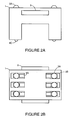
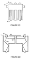
- FIG 2 shows a chip card connector according to one embodiment of the invention.
- Figure 2A shows the chip card connector from the side, Figure 2B from above, Figure 2C from the end, and Figure 2D as a side projection.
- the chip card connector according to this embodiment preferably comprises an insulating plastic frame 1, holders, such as holding juts 2, for pressing the connector to the circuit board, metal balls 3A, openings 3B shaped for the metal balls in the frame 1, and electrically conducting connecting springs, which are here divided into part 4A, which flexibly supports the metal ball 3A in the opening 3B, part 4B fastened to the frame 1, and part 4C pressing against the circuit board.
- the fasteners can also be shaped in other ways than presented above, such as inserts or grooves.
- the holders can also be replaced by soldering the connecting springs to the circuit board.
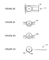
- Figures 2E, 2F, 2G and 2H show an electrically conductive ball 3A, preferably a metal ball, an opening 3B shaped to support the metal ball flexibly from the sides, and the part 4A which flexibly supports the metal ball 3A of the connecting spring in the opening 3B as en enlargement from the top, twice from the end and as a side projection.
- the part 4A of the connecting spring is not shown entirely in figures 2E, 2F and 2G.
- the ball 3A can be loose or fastened to the connecting spring.
- Figure 2F shows how the ball 3A can be kept loose in the ball bed 4AA by means of the narrowness of the opening 3B1 so that the ball 3A cannot slip through it.
- Figure 2G shows how the ball 3A is supported only by the edges of the opening 3B 1 when fastened.
- Figure 2H shows a ball bed 4AA formed in the connection spring 4A, and a metal ball 3A, which is fastened to the ball bed by welding 4AB, for example.
- FIG 3 shows a chip card connector according to another embodiment of the invention.
- Figure 3A shows the chip card connector from the side, Figure 3B from above, Figure 3C from the end, and Figure 3D as a side projection.
- the chip card connector according to this embodiment preferably comprises a plastic frame 5, holding juts 6 for pressing the connector to the circuit board, electrically conducting connecting springs, which are here divided into a flexible, convex contact part 7A, a part 7B fastened to the frame 5, and a part 7C pressing against the circuit board, and openings 8 which are shaped for the convex contact part 7A of the connecting springs and which support the connecting springs from the sides.
- the holding juts 6 of this embodiment can also be shaped differently or be replaced by soldering the connecting springs to the circuit board.
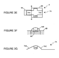
- FIGS 3E, 3F and 3G show a detailed enlargement of the convex contact part 7A of the connecting spring and the opening 8 from above, the end and as a side projection.
- the convex contact part 7A of the connecting spring includes a straight, downward bent, preferably plate-like end part 7AA, on the sides downward bent, convex wings 7AB and a preferably plate-like frame 7AC.
- the opening 8 includes a narrow part 8A, which is essentially the same width as the end part 7AA of the connecting spring and which supports the end part 7AA in the side direction, and a wide part 8B, which is essentially the width of the wing span 7AB and which supports the wings 7AB in the side direction.
- the wings 7AB can be rounded to enable slipping and to avoid wearing of the edges 8B by bending the ends of the wings 7AB inwards, for example.
- support from the sides or in the side direction means a direction, which is transverse in relation to the longitudinal direction of the connecting spring 4, 7.
- FIG. 4 presents a block diagram about a mobile station, in which a chip card connector according to the invention is used.
- the mobile station comprises a processor 9 for reading the identification information, a memory 10 for saving the programs of the processor 9, an identification card connector 11 according to the invention for connecting to the identification card, a display 12 for displaying information to be presented for the operations, a keyboard 13 for entering the user's password, an audio part 14 for voice transmission, a transceiver 15 and an antenna 16 for connecting to the radio network.
- Figure 5 shows a chip card 17 from the contact side.
- a contact area 18 which comprises eight subareas A, B, C, D, E, F, G, H.
- On the right lower edge of the chip card 17 there is also a cut comer, which ensures that the chip card 17 is always installed in the right position.
- a jut corresponding to the comer is arranged outside the connector according to the invention in order to prevent installing the card in any other position.
- Figure 6 shows a circuit board 19 at the chip card connector.
- the chip card connector is pressed on the area delimited by the broken line 20 so that the lower parts of the connecting springs press on the conductive surfaces 21A-H.
- Figure 7 shows an arrangement with the frame 1 of the chip card connector, holding juts 2, the connecting spring contact parts 3A, such as balls, the chip card 17, the circuit board 19 and the inner shield 22 of the device.
- the chip card connector is pressed against the circuit board 19 by the inner shield 22 of the device and the holding juts 2.
- the application of the connector according to the invention to different kinds of mobile stations for the reading unit, which recognizes the subscriber's identification card, is examined here by way of example.
- the chip card connector according to one embodiment of the invention is installed between the circuit board and the shield of the mobile station so that the edge of the opening in the shield, for example, is used to press the connector against the circuit board.
- an electric contact is made between the contact areas of the circuit board and the connecting springs of the chip card connector.
- the subscriber's identification card is slipped to a hinged holder, by means of which the identification card is pressed against the connecting springs. Due to the connector according to the invention, the identification card can be positioned from any side, whereby the wall on the opposite side of the connecting springs makes the identification card press against the connecting springs.
- the metal ball can also be replaced by a ball made from another material and coated with a conductive material.
- the number of connecting springs can vary according to need.
- the inward bending contact part of the connecting spring can also be shaped in other ways, such as St. Andrew's cross, bent on one side or partial sphere, like a lens.
- the contact part need not have the shape of a known geometrical body, as long as the sliding property of the chip card and the stability of the holding part is ensured by a curved edge and the support of the contact part on the frame of the chip card connector.
- a special holder preferably as in the prior art, is needed to hold the chip card on place. Due to the invention, however, the holder can also allow the installation of the chip card from the sides. The holder can also be implemented as an integral part of the chip card connector.
Landscapes
- Engineering & Computer Science (AREA)
- Artificial Intelligence (AREA)
- Computer Vision & Pattern Recognition (AREA)
- Physics & Mathematics (AREA)
- General Physics & Mathematics (AREA)
- Theoretical Computer Science (AREA)
- Coupling Device And Connection With Printed Circuit (AREA)
- Multi-Conductor Connections (AREA)
- Credit Cards Or The Like (AREA)
- Telephone Set Structure (AREA)
Abstract
Description
- Figure 1
- shows a prior art chip card connector, which is soldered on the circuit board.
- Figure 2
- shows a chip card connector according to one embodiment of the invention.
- Figure 3
- shows a chip card connector according to another embodiment of the invention.
- Figure 4
- shows a block diagram about a mobile station, in which a chip card connector according to one embodiment of the invention is used.
- Figure 5
- shows a chip card from the side of the connection,
- Figure 6
- shows a circuit board at the chip card connector, and
- Figure 7
- shows an arrangement of a circuit board, chip card connector and an installed chip card.
Claims (13)
- A chip card connector, which comprises an insulating frame and at least one elongated, electrically conductive connecting spring (4, 7), which contains a part which is designed for touching the contact area (18) of the chip card and which has a bent shape mainly in the longitudinal direction of the connecting spring, characterized in that the part designed for touching (3A, 7A) has a bent shape both in the longitudinal and transverse direction, and the frame (1, 5) comprises at least one supporting part (3B, 8A, 8B) to prevent movement of said part in the plane direction of the chip card (17), the transverse direction of the connecting spring.
- A chip card connector according to Claim 1, characterized in that the frame (1, 5) of the chip card connector is equipped with shaped holders (2, 6) for pressing a connector to a circuit board (19) in order to provide the electric contact to the connecting springs (4, 7).
- A chip card connector according to Claim 1, characterized in that the connecting spring (4) comprisesa flexible part (4A) with a ball bed (4AA) and a ball (3A), which has at least an electrically conductive surface, for touching the contact area (18) of the chip card,a part (4B) fastened to the frame (1), anda part (4C) to be pressed against the circuit board for making an electric contact on said contact area of said circuit board.
- A chip card connector according to Claim 3, characterized in that the frame (1) comprises an opening (3B), which supports the electrically conductive ball from the sides in relation to the longitudinal direction of the connecting spring.
- A chip card connector according to Claim 3, characterized in that at least the surface of the ball (3A) is made of metal and placed as floating on the ball bed (4AA) of the connecting spring (4A) so that the opening (3B) of the frame (1), which supports the ball is at least in one direction smaller than the diameter of the ball.
- A chip card connector according to Claim 3, characterized in that the ball (3A) is made of metal and fastened to the ball bed (4AA) of the connecting spring (4A) by welding (4AB).
- A chip card connector according to Claim 1, characterized in that the connecting spring (7) comprisesa flexible, convex contact part (7A) with a downward bent, plate-like end part (7AA), on the sides downward bent, convex wings (7AB) and a plate-like frame (7AC),a part (7B) fastened to the frame (5), anda part (7C) pressing against the circuit board (19).
- A chip card connector according to Claim 7, characterized in that the frame (5) comprises an opening (8) which is shaped for the flexible, convex contact part (7A) of the connecting spring and which comprises a narrow part (8A) essentially of the width of the end part (7AA), which supports said end part of the connecting spring from the sides, and a wide part (8B) essentially of the width of the span of the wings (7AB), which supports said wings of said connecting spring from said sides.
- An electronic device, which comprises a processor (9) for reading information of a chip card (17), a memory (10) for saving programs of the processor (9), a chip card connector (11) for connecting to the chip card (17), at least one printing unit (12, 14) for printing information to be presented for operations, and an input device (13) for using the operations, characterized in that the chip card connector comprises an insulating frame (1, 5) and connecting springs (4, 7) and that a part of at least one connecting spring (4, 7) provided for touching on a contact area (18) of the chip card is bent in at least two directions, and said frame (1, 5) comprises at least one supporting part to prevent movement in the plane direction of said chip card (17), the transverse direction of said connecting spring (4, 7).
- A mobile station, which comprises a processor (9) for reading identification information of an identification card (17) of a subscriber, a memory (10) for saving programs of the processor (9), an identification card connector (11) for connecting to the identification card (17) of the subscriber, at least one printing unit (12, 14) for printing information to be presented for operations, an input device (13) for using the operations, a transceiver (15) and an antenna (16) for connecting to a radio network, characterized in that the identification card connector comprises an insulating frame (1, 5) and connecting springs (4, 7) and that a part of at least one connecting spring provided for touching on a contact area (18) of the chip card is bent in at least two directions, and said frame (1, 5) comprises at least one supporting part to prevent movement in the plane direction of said chip card (17), the transverse direction of said connecting spring (4, 7).
- A mobile station according to Claim 10, characterized in that the frame (1, 5) of the identification card connector is equipped with shaped holders (2, 6) for pressing said connector by means of an inner shell (22) of the mobile station to a circuit board (19) in order to provide an electric contact to the connecting springs (4, 7).
- A mobile station according to Claim 10, characterized in that the connecting spring (4) of the identification card connector containsa flexible part (4A) with a ball bed (4AA) and a ball (3A), which has at least an electrically conductive surface, for touching the contact area (18) of the chip card,a part (4B) fastened to the frame (1), anda part (4C) to be pressed against a circuit board for conducting electricity.
- A mobile station according to Claim 10, characterized in that the frame (1) contains an opening (3B), the edges of which support the electrically conductive ball from the sides in relation to the longitudinal direction of the connecting spring.
Applications Claiming Priority (2)
| Application Number | Priority Date | Filing Date | Title |
|---|---|---|---|
| FI991002A FI991002L (en) | 1999-05-03 | 1999-05-03 | Smart card slot and mobile station |
| FI991002 | 1999-05-03 |
Publications (2)
| Publication Number | Publication Date |
|---|---|
| EP1050842A2 true EP1050842A2 (en) | 2000-11-08 |
| EP1050842A3 EP1050842A3 (en) | 2001-11-21 |
Family
ID=8554574
Family Applications (1)
| Application Number | Title | Priority Date | Filing Date |
|---|---|---|---|
| EP00660078A Withdrawn EP1050842A3 (en) | 1999-05-03 | 2000-04-28 | Chip card connector and mobile station |
Country Status (5)
| Country | Link |
|---|---|
| US (1) | US6497364B1 (en) |
| EP (1) | EP1050842A3 (en) |
| JP (2) | JP4662605B2 (en) |
| CN (1) | CN1272740A (en) |
| FI (1) | FI991002L (en) |
Cited By (2)
| Publication number | Priority date | Publication date | Assignee | Title |
|---|---|---|---|---|
| FR2816451A1 (en) * | 2000-11-07 | 2002-05-10 | Framatome Connectors Int | CONNECTOR FOR PRINTED CIRCUIT CARD FOR ESTABLISHING CONTACT FROM IC CARDS, ESPECIALLY SIM CARDS, IN MOBILE PHONES |
| US6857908B2 (en) | 2002-01-28 | 2005-02-22 | Gmbh & Co. Kg | Connector with movable contact elements |
Families Citing this family (6)
| Publication number | Priority date | Publication date | Assignee | Title |
|---|---|---|---|---|
| FI991002L (en) * | 1999-05-03 | 2000-11-04 | Nokia Mobile Phones Ltd | Smart card slot and mobile station |
| CN201112707Y (en) * | 2007-08-10 | 2008-09-10 | 富士康(昆山)电脑接插件有限公司 | electrical connector |
| US9209559B2 (en) | 2011-05-13 | 2015-12-08 | Molex, Llc | Power connector |
| JP5818366B2 (en) * | 2012-08-07 | 2015-11-18 | モレックス エルエルシー | Card connector |
| CN104505622B (en) * | 2014-12-18 | 2017-01-11 | 中航光电科技股份有限公司 | Chip mounting structure and connector with chip mounting structure |
| CN117805595B (en) * | 2024-02-29 | 2024-05-03 | 国网辽宁省电力有限公司 | A real-time reactive power compensation detection device based on high voltage SVG |
Family Cites Families (32)
| Publication number | Priority date | Publication date | Assignee | Title |
|---|---|---|---|---|
| US3581019A (en) * | 1968-07-30 | 1971-05-25 | Cessna Aircraft Co | Card control of radio telephone |
| JPS4888482U (en) * | 1972-01-28 | 1973-10-25 | ||
| DE3943703C2 (en) * | 1989-09-21 | 2001-06-21 | Amphenol Tuchel Elect | Smart card reader |
| DE59108764D1 (en) * | 1990-01-30 | 1997-08-14 | Amphenol Tuchel Elect | Contacting device for an SI module |
| GB9020002D0 (en) * | 1990-09-13 | 1990-10-24 | Amp Holland | Card reader |
| US5325429A (en) * | 1992-06-08 | 1994-06-28 | Motorola, Inc. | Apparatus for accepting and retaining an information card |
| DE4243076C2 (en) * | 1992-12-18 | 2000-08-31 | Amphenol Tuchel Elect | Kotaktiereinrichtung for a chip card |
| FR2714539B1 (en) * | 1993-12-24 | 1996-01-26 | Itt Composants Instr | Electrical connector for the connection of an electronic memory card. |
| DE9407499U1 (en) * | 1994-05-05 | 1995-09-07 | Itt Composants Et Instruments, Dole Cedex | Electrical contact element |
| US5633490A (en) * | 1994-11-21 | 1997-05-27 | Oki Electric Industry Co., Ltd. | Card reader with spring contacts |
| FR2730328B1 (en) * | 1995-02-03 | 1997-04-04 | Connectors Pontarlier | CONNECTOR FOR MICROCIRCUIT CARD READING APPARATUS AND MICROCIRCUIT CARD READING APPARATUS INCLUDING SAME |
| US5714742A (en) * | 1995-05-10 | 1998-02-03 | Matsushita Electric Industrial Co., Ltd. | IC-card reader/writer for an IC-card |
| FR2737352B1 (en) * | 1995-07-28 | 1997-08-29 | Itt Composants Instr | ELECTRICAL CONNECTOR FOR CONNECTION OF A CARD WITH AN INTEGRATED CIRCUIT (S) WITH CONTACT |
| FR2745102B1 (en) * | 1996-02-16 | 1998-03-20 | Cga Hbs | THICKNESS FILTER DEVICE IN AN INTRODUCTION CHANNEL OF A TITLE READER SUCH AS TICKETS, CARDS |
| EP0883855B1 (en) | 1996-02-29 | 1999-12-08 | The Whitaker Corporation | Apparatus for the electrical connection of a chip card to a printed circuit board |
| JPH09274977A (en) * | 1996-04-04 | 1997-10-21 | Olympus Optical Co Ltd | Card connector device |
| EP0833271A3 (en) * | 1996-09-20 | 1998-06-17 | Siemens Aktiengesellschaft | Chipcard reader |
| US5894597A (en) * | 1996-09-24 | 1999-04-13 | Motorola, Inc. | Communication device for different sized cards |
| AU5778898A (en) * | 1997-02-04 | 1998-08-25 | Esther Russo | Smartcard electromechanical acceptor device |
| JP3459534B2 (en) * | 1997-03-27 | 2003-10-20 | 株式会社日立ハイテクインスツルメンツ | Component supply device in electronic component mounting device |
| JP3122935B2 (en) * | 1997-05-19 | 2001-01-09 | 日本航空電子工業株式会社 | connector |
| DE29718773U1 (en) * | 1997-10-22 | 1997-12-04 | Stocko Metallwarenfabriken Henkels & Sohn GmbH & Co, 42327 Wuppertal | Chip card contact unit |
| DE19755715A1 (en) * | 1997-12-15 | 1999-06-24 | Amphenol Tuchel Elect | Smart card reader |
| DE19825808B4 (en) * | 1998-06-09 | 2006-10-26 | Amphenol-Tuchel Electronics Gmbh | Contact element for chip card contacting device |
| DE19829551C2 (en) * | 1998-07-02 | 2000-12-14 | Amphenol Tuchel Elect | Contact carrier |
| FR2782816B1 (en) | 1998-08-28 | 2000-11-10 | Framatome Connectors Int | SIM CARD READER CONNECTOR |
| JP3032508B1 (en) * | 1998-11-06 | 2000-04-17 | 焼津ミール協業組合 | Method for producing health food using squid shell and bonito offal as main ingredients |
| US6050857A (en) | 1998-12-22 | 2000-04-18 | Hon Hai Precision Ind. Co., Ltd. | SIM connector and related contact |
| DE19913923A1 (en) * | 1999-03-26 | 2000-09-28 | Amphenol Tuchel Elect | Contacting device for a SIM card |
| FI991002L (en) * | 1999-05-03 | 2000-11-04 | Nokia Mobile Phones Ltd | Smart card slot and mobile station |
| US6234844B1 (en) * | 2000-06-28 | 2001-05-22 | Berg Technology, Inc. | Electronic card connector |
| US6334786B1 (en) * | 2000-11-14 | 2002-01-01 | Super Link Electronics Co., Ltd. | Subscriber identification module card fixing seat with slidable and laterally latching cover |
-
1999
- 1999-05-03 FI FI991002A patent/FI991002L/en unknown
-
2000
- 2000-04-28 EP EP00660078A patent/EP1050842A3/en not_active Withdrawn
- 2000-05-03 US US09/563,387 patent/US6497364B1/en not_active Expired - Lifetime
- 2000-05-08 JP JP2000139403A patent/JP4662605B2/en not_active Expired - Lifetime
- 2000-05-08 CN CN00108159A patent/CN1272740A/en active Pending
-
2010
- 2010-03-18 JP JP2010062622A patent/JP2010153392A/en active Pending
Cited By (3)
| Publication number | Priority date | Publication date | Assignee | Title |
|---|---|---|---|---|
| FR2816451A1 (en) * | 2000-11-07 | 2002-05-10 | Framatome Connectors Int | CONNECTOR FOR PRINTED CIRCUIT CARD FOR ESTABLISHING CONTACT FROM IC CARDS, ESPECIALLY SIM CARDS, IN MOBILE PHONES |
| EP1205869A1 (en) * | 2000-11-07 | 2002-05-15 | Fci | Connector for printed circuit card for placing IC cards and in particular SIM cards, in contact in mobile telephones |
| US6857908B2 (en) | 2002-01-28 | 2005-02-22 | Gmbh & Co. Kg | Connector with movable contact elements |
Also Published As
| Publication number | Publication date |
|---|---|
| FI991002A7 (en) | 2000-11-04 |
| FI991002L (en) | 2000-11-04 |
| CN1272740A (en) | 2000-11-08 |
| JP2001023712A (en) | 2001-01-26 |
| JP4662605B2 (en) | 2011-03-30 |
| JP2010153392A (en) | 2010-07-08 |
| EP1050842A3 (en) | 2001-11-21 |
| US6497364B1 (en) | 2002-12-24 |
| FI991002A0 (en) | 1999-05-03 |
Similar Documents
| Publication | Publication Date | Title |
|---|---|---|
| JP2010153392A (en) | Connector for chip card and mobile station | |
| JP2934857B2 (en) | Electrical switch assembly | |
| JP3421835B2 (en) | Contact support | |
| SG191437A1 (en) | Electrical connector assembly | |
| US6743028B2 (en) | Electrical connector for attaching a circuit board | |
| US6169521B1 (en) | Built-in antenna | |
| KR20020000004U (en) | Surface mount electrical connector | |
| US20090137136A1 (en) | Housing, Terminal and Connector Using Housing and Terminal | |
| JP2006179451A (en) | Non-grounded electric connector | |
| US7052289B1 (en) | Conductive terminal and the electrical connector using the conductive terminal | |
| US7297007B2 (en) | Conductive terminal and the electrical connector using the conductive terminal | |
| JP4794905B2 (en) | IC card connector terminal mounting method | |
| CN108604755B (en) | Electronic equipment | |
| US6918792B2 (en) | Memory card connector | |
| US7137841B1 (en) | LIF socket connector | |
| US20040204090A1 (en) | Elevated data card reader | |
| ATE212474T1 (en) | FUSE HOLDER WITH RECEIVING CONTACT SPRINGS FOR PCB MOUNTING | |
| CN216437182U (en) | Positioning sensing device | |
| CN215815671U (en) | Key assembly and terminal equipment | |
| KR19980080849A (en) | Board Electrical Connectors | |
| JP2002260763A (en) | connector | |
| KR100677338B1 (en) | SIM card connection device of portable terminal | |
| JP4169458B2 (en) | Contact arrangement method for memory card connector | |
| CN211653666U (en) | Non-contact card reading device | |
| KR100778364B1 (en) | Antenna feeding device and portable terminal having same |
Legal Events
| Date | Code | Title | Description |
|---|---|---|---|
| PUAI | Public reference made under article 153(3) epc to a published international application that has entered the european phase |
Free format text: ORIGINAL CODE: 0009012 |
|
| AK | Designated contracting states |
Kind code of ref document: A2 Designated state(s): AT BE CH CY DE DK ES FI FR GB GR IE IT LI LU MC NL PT SE Kind code of ref document: A2 Designated state(s): DE FR GB IT |
|
| AX | Request for extension of the european patent |
Free format text: AL;LT;LV;MK;RO;SI |
|
| PUAL | Search report despatched |
Free format text: ORIGINAL CODE: 0009013 |
|
| AK | Designated contracting states |
Kind code of ref document: A3 Designated state(s): AT BE CH CY DE DK ES FI FR GB GR IE IT LI LU MC NL PT SE |
|
| AX | Request for extension of the european patent |
Free format text: AL;LT;LV;MK;RO;SI |
|
| RAP1 | Party data changed (applicant data changed or rights of an application transferred) |
Owner name: NOKIA CORPORATION |
|
| 17P | Request for examination filed |
Effective date: 20020413 |
|
| AKX | Designation fees paid |
Free format text: DE FR GB IT |
|
| STAA | Information on the status of an ep patent application or granted ep patent |
Free format text: STATUS: THE APPLICATION HAS BEEN WITHDRAWN |
|
| 18W | Application withdrawn |
Effective date: 20030205 |