EP1050676A2 - Engine position sensing - Google Patents
Engine position sensing Download PDFInfo
- Publication number
- EP1050676A2 EP1050676A2 EP00303806A EP00303806A EP1050676A2 EP 1050676 A2 EP1050676 A2 EP 1050676A2 EP 00303806 A EP00303806 A EP 00303806A EP 00303806 A EP00303806 A EP 00303806A EP 1050676 A2 EP1050676 A2 EP 1050676A2
- Authority
- EP
- European Patent Office
- Prior art keywords
- engine
- cylinder
- fuel
- acceleration sensor
- speed
- Prior art date
- Legal status (The legal status is an assumption and is not a legal conclusion. Google has not performed a legal analysis and makes no representation as to the accuracy of the status listed.)
- Withdrawn
Links
- 230000001133 acceleration Effects 0.000 claims abstract description 69
- 238000000034 method Methods 0.000 claims abstract description 69
- 239000000446 fuel Substances 0.000 claims abstract description 63
- 238000002485 combustion reaction Methods 0.000 claims abstract description 21
- 238000012544 monitoring process Methods 0.000 claims abstract description 17
- 230000004044 response Effects 0.000 claims description 6
- 230000000630 rising effect Effects 0.000 claims description 4
- 230000006870 function Effects 0.000 claims description 3
- 238000002347 injection Methods 0.000 description 17
- 239000007924 injection Substances 0.000 description 17
- 238000001514 detection method Methods 0.000 description 10
- 238000005259 measurement Methods 0.000 description 9
- 230000006835 compression Effects 0.000 description 7
- 238000007906 compression Methods 0.000 description 7
- 238000010304 firing Methods 0.000 description 5
- 238000001914 filtration Methods 0.000 description 3
- 230000002159 abnormal effect Effects 0.000 description 2
- 230000001419 dependent effect Effects 0.000 description 2
- 238000010586 diagram Methods 0.000 description 2
- 230000005856 abnormality Effects 0.000 description 1
- 238000012937 correction Methods 0.000 description 1
- 238000013461 design Methods 0.000 description 1
- 239000002283 diesel fuel Substances 0.000 description 1
- 230000010354 integration Effects 0.000 description 1
- 238000013507 mapping Methods 0.000 description 1
- 238000012360 testing method Methods 0.000 description 1
Images

Classifications
-
- F—MECHANICAL ENGINEERING; LIGHTING; HEATING; WEAPONS; BLASTING
- F02—COMBUSTION ENGINES; HOT-GAS OR COMBUSTION-PRODUCT ENGINE PLANTS
- F02D—CONTROLLING COMBUSTION ENGINES
- F02D41/00—Electrical control of supply of combustible mixture or its constituents
- F02D41/0097—Electrical control of supply of combustible mixture or its constituents using means for generating speed signals
-
- F—MECHANICAL ENGINEERING; LIGHTING; HEATING; WEAPONS; BLASTING
- F02—COMBUSTION ENGINES; HOT-GAS OR COMBUSTION-PRODUCT ENGINE PLANTS
- F02D—CONTROLLING COMBUSTION ENGINES
- F02D41/00—Electrical control of supply of combustible mixture or its constituents
- F02D41/009—Electrical control of supply of combustible mixture or its constituents using means for generating position or synchronisation signals
-
- F—MECHANICAL ENGINEERING; LIGHTING; HEATING; WEAPONS; BLASTING
- F02—COMBUSTION ENGINES; HOT-GAS OR COMBUSTION-PRODUCT ENGINE PLANTS
- F02D—CONTROLLING COMBUSTION ENGINES
- F02D41/00—Electrical control of supply of combustible mixture or its constituents
- F02D41/02—Circuit arrangements for generating control signals
- F02D41/04—Introducing corrections for particular operating conditions
- F02D41/06—Introducing corrections for particular operating conditions for engine starting or warming up
- F02D41/062—Introducing corrections for particular operating conditions for engine starting or warming up for starting
-
- F—MECHANICAL ENGINEERING; LIGHTING; HEATING; WEAPONS; BLASTING
- F02—COMBUSTION ENGINES; HOT-GAS OR COMBUSTION-PRODUCT ENGINE PLANTS
- F02D—CONTROLLING COMBUSTION ENGINES
- F02D41/00—Electrical control of supply of combustible mixture or its constituents
- F02D41/02—Circuit arrangements for generating control signals
- F02D41/14—Introducing closed-loop corrections
- F02D41/1497—With detection of the mechanical response of the engine
-
- F—MECHANICAL ENGINEERING; LIGHTING; HEATING; WEAPONS; BLASTING
- F02—COMBUSTION ENGINES; HOT-GAS OR COMBUSTION-PRODUCT ENGINE PLANTS
- F02D—CONTROLLING COMBUSTION ENGINES
- F02D41/00—Electrical control of supply of combustible mixture or its constituents
- F02D41/02—Circuit arrangements for generating control signals
- F02D41/14—Introducing closed-loop corrections
- F02D41/1497—With detection of the mechanical response of the engine
- F02D41/1498—With detection of the mechanical response of the engine measuring engine roughness
-
- F—MECHANICAL ENGINEERING; LIGHTING; HEATING; WEAPONS; BLASTING
- F02—COMBUSTION ENGINES; HOT-GAS OR COMBUSTION-PRODUCT ENGINE PLANTS
- F02D—CONTROLLING COMBUSTION ENGINES
- F02D2200/00—Input parameters for engine control
- F02D2200/02—Input parameters for engine control the parameters being related to the engine
- F02D2200/10—Parameters related to the engine output, e.g. engine torque or engine speed
- F02D2200/1015—Engines misfires
Definitions
- This invention relates to a method of sensing the operating position of an engine, the method being particularly suitable for use in controlling the operation of a compression ignition internal combustion engine.
- a compression ignition internal combustion engine includes a number of cylinders, commonly four or six, into which fuel is injected, each cylinder having an associated fuel injector for injecting fuel into the cylinder. It is important to be able to determine the operating position of the engine to permit fuel to be delivered at an appropriate time to each cylinder of the engine.
- a crankshaft position sensor is used to provide a signal indicative of one or more of the engine cylinders occupying a top-dead-centre position, this signal being used in controlling the timing of fuel delivery, and a camshaft position sensor is used to provide a signal indicative of which cylinder fuel should be delivered to.
- the provision of two such sensors and the associated wiring is relatively complex and adds to the cost of the engine, and it is an object of the invention to provide a method of sensing the position of an engine in which the provision of one of the sensors is omitted.
- European Patent Application No 98309856.7 which relates to a method of controlling the operation of a compression ignition internal combustion engine by monitoring the output signal of an accelerometer associated with the engine.
- the accelerometer senses vibration of the engine and by monitoring the output of the accelerometer during the fuel injection cycle, abnormalities in the combustion stage of the cycle can be detected.
- the method also permits abnormal pilot injection to be detected.
- a method of sensing the position of an engine comprising using the output of a position/speed sensor to determine when a cylinder of the engine has reached a predetermined position, the output of the position/speed sensor also being used to identify to which cylinder or combustion space of the engine fuel should next be delivered.
- the position/speed sensor preferably comprises a crankshaft position/speed sensor, for example comprising a toothed wheel arranged to rotate at crankshaft speed, the tooth spacing defining a gap which can be identified to provide an indication of the crankshaft position, the rate of movement of the teeth past a predetermined position providing an indication of the instantaneous engine speed.
- a crankshaft position/speed sensor for example comprising a toothed wheel arranged to rotate at crankshaft speed, the tooth spacing defining a gap which can be identified to provide an indication of the crankshaft position, the rate of movement of the teeth past a predetermined position providing an indication of the instantaneous engine speed.
- the engine speed varies in a cyclical manner.
- the engine has an odd number of cylinders, for example a three or five cylinder engine
- the predetermined position for example the top-dead-centre position
- the next cylinder to which fuel should be delivered can be positively identified.
- This engine speed derived criterion may be tabulated for instance as a function or average speed and as a function of load when injection occurs.
- Such a technique may be used in conjunction with a technique whereby, when the engine is to be switched off, the engine stops in or close to a known position. As a result, the engine can be stopped in a position whereby the actual engine position can be determined, accurately, very quickly upon restarting the engine.
- the detection of the predetermined position may be used to identify two cylinders, one of which is the one to which fuel should be delivered next. Fuel is then supplied to one of the cylinders and the engine monitored to determine whether or not the cylinder fires. If so, then the engine position is known. If not, then the one to which fuel should have been delivered is the other of the two identified cylinders, and the engine position is known.
- the choice of to which of the two cylinders fuel is delivered can be made, for example, based upon which cylinder was last fired, the engine speed and the time elapsed since that cylinder fired, or based upon the position in which the engine was forced to stop.
- a method of sensing the position of an engine including the steps of sensing vibrations of the engine using acceleration sensor means and monitoring the or each output signal of the acceleration sensor means so as to determine the position of the engine.
- the method may include the steps of providing each cylinder of the engine with an acceleration sensor so as to sense vibrations occurring in each of the cylinders, the acceleration sensors generating an output signal in response to a vibration in the associated cylinder having a signal magnitude and frequency characteristic.
- the method may include the step of providing a single acceleration sensor in the engine, the acceleration sensor generating an output signal in response to a vibration in the engine having a signal magnitude and frequency characteristic.
- the method may include the further step of comparing the signal magnitudes of the acceleration sensor output signals to determine engine position.
- the method may include the further step of comparing the frequency characteristics of the acceleration sensor output signals to determine engine position.
- the method may include the further step of estimating the engine position and using the method of the invention to confirm that the estimated engine position is correct.
- the method of estimation of engine position may be by means of a crank angle sensor provided on the engine, or by remembering the position of the engine when it is stopped or by a statistical learning technique.
- the method may include the further step of modifying the estimated position in response to the method of the invention.
- the modified estimate of engine position may be used to control the timing of fuel injected into the engine.
- a control system for sensing the position of an engine including acceleration sensor means for sensing vibrations of the engine and means for monitoring the or each output signal of the acceleration sensor as to determine the position of the engine.
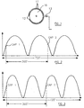
- Figure 1 illustrates a speed and position sensor for use in monitoring the rotational speed and angular position of the crankshaft of an engine.
- the sensor comprises a wheel 10 which is mounted upon or arranged to rotate at the speed of rotation of the crankshaft.
- the wheel 10 is provided with external, radially extending teeth which are equiangularly spaced around the wheel 10, apart from a gap region 12 of the wheel 10 in which two of the teeth are missing.
- the wheel 10 is located such that as the wheel 10 rotates, the teeth 11 move past a transducer 13 or other sensor which is capable of monitoring the movement of the teeth past a predetermined position.
- the output of the transducer 13 will include a series of spikes, each spike being associated with a respective one of the teeth 11 passing the predetermined position.
- the spikes will be equally spaced as the teeth are substantially equiangularly spaced, provided the engine is running at a constant or near constant speed.
- the gap between the spikes produced by the teeth immediately before and after the gap 12 will be relatively long. Detection of this relatively long gap provides an indication of the angular position of the wheel 10 and hence the crankshaft.
- the wheel 10 By arranging for the wheel 10 to be located such that movement of the region 12 past the predetermined position coincides with the top-dead-centre position for one or more of the cylinders of the engine with which the crankshaft is associated, it will be appreciated that when the movement of the region 12 past the transducer 13 is sensed, the engine is in a position in which one or more of the cylinders occupies its top-dead-centre position.
- the movement of the region 12 past the predetermined position may coincide with one or more of the engine cylinders occupying a top-dead-centre position
- the position of the region 12 may be selected such that it moves past the predetermined position at a point prior to or following the top-dead-centre position and provided the relationship between the movement of the region 12 past the predetermined position and the crankshaft position is known, then the crankshaft position can be identified using the crankshaft sensor.
- the senor can also be used to monitor the angular speed of rotation of the crankshaft by monitoring the time interval which occurs between each spike produced by the transducer 13 as each tooth 11 moves past the predetermined position.
- Figure 2 is a diagrammatic representation of the speed of rotation of an engine having three cylinders, the speed of rotation having been measured using a speed and position sensor of the type illustrated in Figure 1. The speed measurements were taken during a period in which no fuel was supplied to any of the cylinders of the engine.
- the engine and crankshaft speed variations illustrated in Figure 2 arise as a result of the compression strokes of the various cylinders of the engine.
- the engine is a three cylinder engine
- three compression strokes of the engine occur over a crankshaft angle of 720°. In this 720° period, as the crankshaft has rotated twice, the movement of the region 12 past the transducer 13 will occur twice, and these occurrences are denoted on Figure 2 by "gap 1" and "gap 2".
- the instantaneous speed of rotation of the wheel 10 is measured, the speed measurement being repeated after the crankshaft has continued movement through a predetermined angle.
- the two speed measurements are compared with one another to determine whether the engine speed is increasing or whether the engine speed is falling. As illustrated in Figure 2, if the engine speed is increasing at the point at which the region 12 moves past the predetermined position, then "gap 1" has been detected. If the engine speed is falling at the point at which the region 12 moved past the predetermined position, then "gap 2" has been sensed.
- the engine position can be accurately sensed.
- "gap 1" may be discriminated from “gap 2" by measuring the engine speed alone rather than by measuring speed changes.
- the method described hereinbefore may be used upon initial start-up of the engine to determine the engine position, and once the engine position has been accurately sensed, delivery of fuel to an appropriate one of the cylinders can take place. Likewise, the method can be used in the event that the engine is running but data indicative of the engine position has been lost.
- the speed measurements at the instants at which the region 12 is sensed may require correction, for example by mapping the instantaneous speed or speed change measurements against the average engine speed.
- Figure 3 illustrates the use of a technique for determining the engine position of a four cylinder engine.
- the method involves sensing the movement of the region 12 past the predetermined position. As the region 12 moves past the predetermined position, the engine must be in one of two known positions, the region equating to either "gap 1" or "gap 2".
- a most likely engine position is derived, for example using the technique described hereinbefore in relation to switching off of the engine or using other criteria, for example the speed at which the engine is rotating and the time since the last combustion took place. Once the most likely cylinder has been identified, a small quantity of fuel is injected into the next cylinder in the engine operating cycle and the engine is monitored to determine whether or not fuel combustion takes place.
- the method described hereinbefore may be used both upon initial start-up of an engine and upon an engine which is already running but in which the position information of the engine has become lost. Where the engine is already running, then it is particularly important to ensure that the quantity of fuel delivered to the engine when testing whether or not the correct cylinder has been located should be sufficiently small to ensure that no damage to the engine can occur.
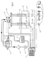
- FIG. 4 shows an engine and fuel system incorporating a control system for implementing an alternative aspect of the present invention.
- the engine and fuel system includes a low pressure fuel pump 8 arranged to draw diesel fuel from a fuel reservoir 9, and supply the fuel through a filter 14 to an inlet of a high pressure fuel pump 16.
- the high pressure fuel pump 16 is arranged to charge a common rail 18 with fuel at high pressure.
- Connected to the common rail 18 is a plurality of injectors 20, each of the injectors 20 being electromagnetically actuable under the control of an electronic control unit 22.
- the electronic control unit 22 also controls the operation of the high pressure fuel pump 16 by controlling a throttle 24 thereof, and controls the fuel pressure within the common rail 18 by controlling the operation of a control valve 26, the electronic control unit 22 being supplied with information relating to the fuel pressure within the common rail 18 by a pressure sensor 28.
- the electronic control unit In addition to receiving signals indicative of the fuel pressure within the common rail 18, the electronic control unit is supplied with signals indicative of a number of other engine parameters, for example engine speed and accelerator pedal position, using appropriate sensors 30, including a crank angle sensor 30a.
- Fuel delivered by the injectors 20 is injected into respective cylinders of an associated engine 32.
- Four acceleration sensors 35a, 35b, 35c, 35d are mounted on the engine 32, one acceleration sensor being associated with each of the four cylinders of the engine.
- the acceleration sensors 35a-35d are sensitive to vibrations associated with each of the cylinders and generate output signals 36a-36d respectively which are supplied to the electronic control unit 22.
- each of the output signals 36a-36d may be passed through a band-pass filter arranged to pass vibration signals falling within a pre-selected frequency range.
- the filtered signal may then be amplified using amplifying means and full wave rectified by a rectifying circuit (not shown in Figure 4).
- the output signals 36a-36d are detected within a detection time interval, or detection window.
- the window used may be of 10 to 30 degrees duration and can be phased in the range indicated below.
- the window may be mapped according to engine speed, load, temperature etc.
- the pan of the output signal 36a-36d falling within this detection time interval is integrated by an appropriate integration circuit and is subsequently input to the electronic control unit 22.
- the detection time interval occurs near the top-dead-centre position for a cylinder for which the signal relates, as will be described hereinafter.
- the actual timing interval may be positioned between a few degrees before TDC to up to 30 degrees after TDC. This position may also be mapped with engine speed, load etc.
- the associated acceleration sensor 35a-35d will generate an output signal 36a-36d having characteristics which depend on the event occurring within the cylinder. By monitoring these characteristics it is therefore possible to determine the position of each cylinder within the injection cycle and, thus, to determine engine position. Information regarding engine position in combination with information derived from, for example, a crankshaft position sensor, can then be used to permit fuel to be delivered at an appropriate time to each cylinder under the control of the electronic control unit 22.
- the output signals obtained from the acceleration sensors can be used to determine engine position. For example, on engine start-up, or during a period when the engine is "free-wheeling", the crankshaft is rotating but no fuel is being supplied to the engine and the engine will not be firing. It is therefore necessary to determine engine position so that the initial injection of fuel, to fire the engine, occurs in the correct cylinder. Also, synchronisation can be lost during running of the engine in which case the engine is likely to be firing. In such circumstances it is necessary to determine engine position so that synchronisation can be recovered.
- engine position is determined by using information obtained from sensors mounted on the cam and crank shafts to determine the cam and crank shaft position.
- the position information derived from the crank shaft sensor alone is ambiguous as it cannot distinguish between the two engine rotation phases.
- the ambiguity can, however, be removed by using the output signals 36a-36d obtained from the acceleration sensors 35a-35d.
- the acceleration sensors 35a-35d are sensitive to vibrations occurring within their respective cylinders and, thus, they can be used to provide a check on whether the engine position, calculated using the crank shaft sensor, is correct.
- the output signals 36a-36d from acceleration sensors 35a-35d can then be analysed to confirm that the cylinder which is determined as the one in which fuel injection is to commence using the aforementioned technique is correct.
- any one of several characteristics of the vibration output signals 36a-36d may be used to confirm engine position in this way.
- the output signals from the accelerometers will have a signal magnitude and frequency characteristic of an engine which is rotating but not firing. It has been found, for example, when the engine fires, that just prior to the top-dead-centre position for the particular cylinder, the vibration signal from the acceleration sensor is large in magnitude.
- the frequency characteristic of the vibration signal from an acceleration sensor associated with a given cylinder is dependent on the position of the cylinder.
- the expected frequency characteristic for a vibration signal corresponding to a cylinder just prior to top-dead-centre position is known, this can be compared with the frequency characteristic from each acceleration sensor 35a-35d to determine which cylinder is the correct cylinder into which fuel injection is to commence.
- crank shaft sensor may be sufficient to identify which cylinder is at top-dead-centre, but is not sufficient to determine the engine rotation phase.
- the crankshaft sensor signal may therefore be used to determine which cylinders have the piston at top-dead-centre and the acceleration sensor output signals 36a-36d can be used to determine which of the cylinders should be supplied with fuel.
- One method suitable for use under such conditions is to deliver a small quantity of fuel to a cylinder which it is assumed is the one which is next to fire.
- the quantity of fuel should be sufficiently small so that, in the event that the assumption is incorrect, damage to the engine is unlikely.
- the assumption is then tested, for example by using the acceleration sensor output signals, to determine whether combustion occurs in that cylinder at the appropriate time.
- Filtering of the signals may be required to emphasise the frequencies of interest, the filtering being achieved by means of appropriate band pass or band stop filters. As described previously, the appropriate filtering means are placed in the output signal path between the acceleration sensors 35a-35d and the electronic control unit 22.
- a single acceleration sensor 38 may be mounted on the engine instead of having a separate acceleration sensor being associated with each cylinder.
- Like parts to those shown in Figure 4 are denoted by like reference numerals and will not therefore be described in further detail.
- Use of only a single acceleration sensor 38 to determine engine position is advantageous as the complexity and cost of the engine is reduced.
- an acceleration sensor is often provided in an engine for other purposes such as, for example, monitoring abnormal combustion or detecting the onset of combustion or injection. Thus, there is no need for an additional acceleration sensor to be provided to implement the sensing method of the present invention.
- the acceleration sensor 38 generates an output signal 40 in response to an engine vibration, and the output signal 40 can be used in several ways to determine engine position. Firstly, the magnitude of the acceleration sensor output signal 40 will be largest when sensing vibrations in the cylinder positioned closest to the sensor 38. Similarly, the magnitude of the output signal 40 will be smallest when sensing vibrations in the cylinder positioned furthest from the sensor 38. Pre-determined magnitudes for a vibration signal corresponding to an event in each of the cylinders are stored in the electronic control unit 22. By comparing the magnitude of the vibration signal provided by the acceleration sensor with the predetermined magnitudes for each cylinder it is therefore possible to determine which cylinder is at top-dead-centre
- the time it takes a vibration signal to be detected by the acceleration sensor can be used to determine in which cylinder a particular event has occurred. Vibration signals corresponding to events occurring in cylinders furthest away from the acceleration sensor will take a longer time to reach the sensor compared to vibration signals corresponding to events occurring in the closest to the acceleration sensor.
- the time delay between an event occurring and the detection of the vibration signal corresponding to the event can be used to determine the cylinder in which the event occurred. For example, piston slap occurs immediately after top-dead-centre as a result of the side thrust on the cylinder piston changing direction.
- a crank shaft position sensor can be used to indicate top-dead-centre.
- the acceleration sensor output provides an indication that a vibration has occurred in the engine due to piston slap.
- the cylinder in which piston slap occurred can therefore be deduced.
- Measurement of a short time difference corresponds to an event in the cylinder located closest to the acceleration sensor, and measurement of a long time difference corresponds to an event in the cylinder located furthest from the acceleration sensor.
- the different decay rates from the acceleration sensor can be used to determine engine position. Due to the design of the engine block, output signals from the acceleration sensor associated with each of the different cylinders will have different decay rates. The decay rates for each cylinder can be measured beforehand. The pre-determined decay rates are then stored in the electronic control unit and, by comparing the measured decay rate of the signal from the acceleration sensor with the predetermined decay rates, it is then possible to determine in which cylinder the vibration detected by the acceleration sensor occurred. Thus, it is possible to determine engine position.
- the output signals from the acceleration sensors associated with each of the different cylinders are likely to have different frequency and amplitude characteristics.
- Pre-determined information regarding the frequency characteristics of each cylinder is stored in the electronic control unit. By comparing the pre-determined information with the measured frequency characteristic of the acceleration sensor output signal, it is possible to identify the cylinder in which the signal originated. Thus, the engine position can be determined.
- engine position may be determined by combining any of the aforementioned methods so that two or more characteristics of the acceleration sensor output signal are used to determine engine position.
- the information derived by monitoring the decay characteristics of the acceleration sensor output signal may be confirmed by comparing the magnitude of the sensor output signal with predetermined signal magnitudes.
Landscapes
- Engineering & Computer Science (AREA)
- Chemical & Material Sciences (AREA)
- Combustion & Propulsion (AREA)
- Mechanical Engineering (AREA)
- General Engineering & Computer Science (AREA)
- Combined Controls Of Internal Combustion Engines (AREA)
Abstract
Description
Claims (22)
- A method of sensing the position of an engine comprising using the output of a position/speed sensor (10, 11, 12, 13) to determine when a cylinder of the engine has reached a predetermined position, the output of the position/speed sensor also being used to identify to which cylinder or combustion space of the engine fuel should next be delivered.
- The method as claimed in Claim 1, wherein the position/speed sensor comprises a crankshaft position/speed sensor.
- The method as claimed in Claim 2, wherein the crankshaft position/speed sensor comprises a toothed wheel (10) provided with a plurality of teeth (11), the wheel (10) being arranged to rotate at crankshaft speed and the spacing of the teeth (11) defining a gap region (12), the method further comprising the steps of identifying the gap region (12) to provide an indication of the crankshaft position and determining the rate of movement of the teeth (11) past a predetermined position to provide an indication of the instantaneous engine speed.
- The method as claimed in any of Claims 1 to 3, comprising the steps of measuring the engine speed at the time at which the predetermined position is sensed so as to permit the next cylinder to which fuel should be delivered to be identified.
- The method as claimed in Claim 4, comprising the step of monitoring the engine speed to determine whether the engine speed is rising or falling so as to permit the next cylinder to which fuel should be delivered to be identified.
- The method as claimed in Claim 4, comprising the step of calculating engine speed derived criterion from the measured engine speed and comparing the calculated engine speed derived criterion with pre-determined engine speed derived criterion so as to permit the next cylinder to which fuel should be delivered to be identified.
- The method as claimed in Claim 6, wherein the engine speed derived criterion are stored in a memory as a function of one or more of engine load or average engine speed.
- The method as claimed in any of Claims 4 to 7, comprising the steps of measuring the engine speed at the time at which the predetermined position is sensed and determining whether the engine speed is rising or falling so as to identify two cylinders, one of which is the one to which fuel should be delivered next, supplying fuel to one of the two identified cylinders and monitoring the engine so as to determine whether or not the cylinder to which fuel is supplied fires, and using the determination of whether or not the cylinder fires to provide an indication of engine position.
- The method as claimed in Claim 8, wherein the one of the two identified cylinders to which fuel is supplied is selected by using an alternative method for determining which is the most likely cylinder to which fuel should be delivered next.
- The method as claimed in Claim 8 or Claim 9, comprising the step of using an accelerometer arranged to monitor frequencies indicative of fuel combustion so as to determine whether or not the cylinder to which fuel is supplied fires.
- The method as claimed in any of Claims 1 to 10, wherein the predetermined position is a cylinder top-dead-centre position.
- A method of sensing the position of an engine, including the steps of sensing vibrations of the engine using acceleration sensor means (35a, 35b, 35c, 35d; 38) providing one or more output signal (36a, 36b, 36c, 36d; 40), and monitoring the or each output signal (36a, 36b, 36c, 36d; 40) of the acceleration sensor means so as to determine the position of the engine.
- The method as claimed in Claim 12, wherein the method includes the steps of providing each cylinder of the engine with an acceleration sensor (35a, 35b, 35c, 35d) so as to sense vibrations occurring in each of the cylinders, each of the acceleration sensors (35a, 35b, 35c, 35d) generating a respective output signal (36a, 36b, 36c, 36d) in response to a vibration in the associated cylinder, each of the output signals having a signal magnitude and frequency characteristic.
- The method as claimed in Claim 13, comprising the further step of comparing the magnitudes of the acceleration sensor output signals (36a, 36b, 36c, 36d) so as to determine engine position.
- The method as claimed in Claim 13 or Claim 14, comprising the step of comparing the frequency characteristics of the acceleration sensor output signals (36a, 36b, 36c, 36d) to determine engine position.
- The method as claimed in Claim 12, wherein the method includes the step of providing a single acceleration sensor (38) in the engine, the acceleration sensor generating an output signal (40) in response to a vibration in the engine, the output signal (40) having a signal magnitude and frequency characteristic.
- The method as claimed in Claim 16, wherein the method includes the step of measuring the time taken for the output signal (40) of the acceleration sensor (38) to be detected and comparing the measured time taken with pre-determined times for each of the engine cylinders to determine in which of the engine cylinders the vibration occurred.
- The method as claimed in Claim 16 or Claim 17, comprising the step of measuring the rate of decay of the output signal (40) from the acceleration sensor (38) and comparing the measured rate of decay with pre-determined rates of decay for each of the engine cylinders to determine in which of the engine cylinders the vibration occurred.
- A method of sensing the position of an engine including the step of estimating the engine position and using the method of any of Claims 1 to 18 to confirm that the estimated engine position is correct.
- The method as claimed Claim 19, including the further step of modifying the estimated position depending on the outcome of the method of Claim 19.
- The method as claimed in Claim 20, including the further step of using the modified engine position to control the timing of fuel injected into the engine.
- A control system for sensing the position of an engine, including acceleration sensor means (35a, 35b, 35c, 35d) for sensing vibrations of the engine and means for monitoring the or each output signal of the acceleration sensor means so as to determine the position of the engine.
Applications Claiming Priority (4)
| Application Number | Priority Date | Filing Date | Title |
|---|---|---|---|
| GBGB9910256.8A GB9910256D0 (en) | 1999-05-05 | 1999-05-05 | Engine position sensing |
| GB9910256 | 1999-05-05 | ||
| GB9920645 | 1999-09-02 | ||
| GBGB9920645.0A GB9920645D0 (en) | 1999-09-02 | 1999-09-02 | Method of sensing engine position |
Publications (2)
| Publication Number | Publication Date |
|---|---|
| EP1050676A2 true EP1050676A2 (en) | 2000-11-08 |
| EP1050676A3 EP1050676A3 (en) | 2002-06-05 |
Family
ID=26315504
Family Applications (1)
| Application Number | Title | Priority Date | Filing Date |
|---|---|---|---|
| EP00303806A Withdrawn EP1050676A3 (en) | 1999-05-05 | 2000-05-05 | Engine position sensing |
Country Status (1)
| Country | Link |
|---|---|
| EP (1) | EP1050676A3 (en) |
Cited By (3)
| Publication number | Priority date | Publication date | Assignee | Title |
|---|---|---|---|---|
| FR2854438A1 (en) * | 2003-05-02 | 2004-11-05 | Bosch Gmbh Robert | Crankshaft identification marks time interval determining method for internal combustion engine, involves determining factors of acceleration of crankshaft from actual data of engine to determine optimum time for fuel injection |
| EP1803916A1 (en) * | 2005-12-30 | 2007-07-04 | Scania CV Aktiebolag (publ) | A method and a system for synchronization |
| US7243862B2 (en) | 2004-04-07 | 2007-07-17 | Delphi Technologies, Inc. | Apparatus and method for mode-switching fuel injector nozzle |
Family Cites Families (8)
| Publication number | Priority date | Publication date | Assignee | Title |
|---|---|---|---|---|
| DE3611262A1 (en) * | 1986-04-04 | 1987-10-08 | Bosch Gmbh Robert | METHOD FOR DETECTING THE WORKING STATE OF A CYLINDER OF AN INTERNAL COMBUSTION ENGINE |
| IT1223825B (en) * | 1988-09-15 | 1990-09-29 | Marelli Autronica | DEVICE AND PROCEDURE FOR THE DETONATION DETECTION IN EIGHT CYCLE ENGINES |
| KR930009907B1 (en) * | 1988-10-04 | 1993-10-13 | 미쯔비시 덴끼 가부시끼가이샤 | Control apparatus for internal combustion engine |
| US5402675A (en) * | 1990-01-26 | 1995-04-04 | Robert Bosch Gmbh | Method for recognizing the power stroke of a four-stroke engine |
| DE4418579B4 (en) * | 1994-05-27 | 2004-12-02 | Robert Bosch Gmbh | Device for regulating an internal combustion engine |
| DE19521277A1 (en) * | 1995-06-10 | 1996-12-12 | Bosch Gmbh Robert | Device for cylinder detection in a multi-cylinder internal combustion engine |
| JP3186545B2 (en) * | 1995-10-06 | 2001-07-11 | 三菱電機株式会社 | 4-cycle internal combustion engine controller |
| DE19638010A1 (en) * | 1996-09-18 | 1998-03-19 | Bosch Gmbh Robert | Method for determining the phase position in a 4-stroke internal combustion engine |
-
2000
- 2000-05-05 EP EP00303806A patent/EP1050676A3/en not_active Withdrawn
Cited By (3)
| Publication number | Priority date | Publication date | Assignee | Title |
|---|---|---|---|---|
| FR2854438A1 (en) * | 2003-05-02 | 2004-11-05 | Bosch Gmbh Robert | Crankshaft identification marks time interval determining method for internal combustion engine, involves determining factors of acceleration of crankshaft from actual data of engine to determine optimum time for fuel injection |
| US7243862B2 (en) | 2004-04-07 | 2007-07-17 | Delphi Technologies, Inc. | Apparatus and method for mode-switching fuel injector nozzle |
| EP1803916A1 (en) * | 2005-12-30 | 2007-07-04 | Scania CV Aktiebolag (publ) | A method and a system for synchronization |
Also Published As
| Publication number | Publication date |
|---|---|
| EP1050676A3 (en) | 2002-06-05 |
Similar Documents
| Publication | Publication Date | Title |
|---|---|---|
| US5041980A (en) | Method and apparatus for producing fault signals responsive to malfunctions in individual engine cylinders | |
| JP5099258B2 (en) | Torque estimation device for internal combustion engine | |
| JP3261212B2 (en) | Cylinder discrimination method for fuel injection device of internal combustion engine | |
| US5970784A (en) | Method for identifying the cylinder phase of an internal combustion multi-cylinder four stroke engine | |
| EP2390489B1 (en) | Apparatus and method for estimating bounce back angle of a stopped engine | |
| JPS60201232A (en) | How to diagnose peak compression pressure in the cylinders of an internal combustion engine with a power crankshaft | |
| JPH0130098B2 (en) | ||
| US20140299080A1 (en) | Method for estimating the angular position of a crankshaft for accelerating the starting of an internal combustion engine | |
| GB2052070A (en) | Diagnosis of engine turbocharger performance | |
| US5860406A (en) | Engine timing apparatus and method of operating same | |
| US6415655B2 (en) | Method of synchronization of multi-cylinder internal combustion engine | |
| US6253145B1 (en) | Synchronization of internal combustion engine | |
| JPH0586953A (en) | Crank angle and cylinder deciding method for internal combustion engine | |
| CN102305139B (en) | Starting method for four-stroke electronic injection diesel engine | |
| US6907342B1 (en) | Method and apparatus for detecting a crank angle in an engine | |
| CN101952579A (en) | Method for producing an internal combustion engine operating cycle synchronization signal | |
| JP2807737B2 (en) | Device for detecting combustion state of internal combustion engine | |
| JPH11132089A (en) | Method and apparatus for detecting the combustion cycle of a given cylinder at the start of an internal combustion engine | |
| JP2001289109A (en) | Method for detecting a combustion stroke in a single cylinder four stroke engine | |
| US20020092499A1 (en) | Detonation sensing of crankshaft position | |
| US5503007A (en) | Misfire detection method and apparatus therefor | |
| US5562082A (en) | Engine cycle identification from engine speed | |
| JPS6340934B2 (en) | ||
| KR0121319B1 (en) | Method and device for sensing the direction of crankshaft rotation in a diesel engine | |
| EP1507077A2 (en) | Engine cycle recognition for fuel delivery |
Legal Events
| Date | Code | Title | Description |
|---|---|---|---|
| PUAI | Public reference made under article 153(3) epc to a published international application that has entered the european phase |
Free format text: ORIGINAL CODE: 0009012 |
|
| AK | Designated contracting states |
Kind code of ref document: A2 Designated state(s): AT BE CH CY DE DK ES FI FR GB GR IE IT LI LU MC NL PT SE |
|
| AX | Request for extension of the european patent |
Free format text: AL;LT;LV;MK;RO;SI |
|
| RIN1 | Information on inventor provided before grant (corrected) |
Inventor name: SCHIETECATTE, THIERRY Inventor name: DUPRAZ, PIERRE Inventor name: MEISSONNIER, GUILLAUME |
|
| PUAL | Search report despatched |
Free format text: ORIGINAL CODE: 0009013 |
|
| AK | Designated contracting states |
Kind code of ref document: A3 Designated state(s): AT BE CH CY DE DK ES FI FR GB GR IE IT LI LU MC NL PT SE |
|
| AX | Request for extension of the european patent |
Free format text: AL;LT;LV;MK;RO;SI |
|
| AKX | Designation fees paid | ||
| REG | Reference to a national code |
Ref country code: DE Ref legal event code: 8566 |
|
| STAA | Information on the status of an ep patent application or granted ep patent |
Free format text: STATUS: THE APPLICATION IS DEEMED TO BE WITHDRAWN |
|
| 18D | Application deemed to be withdrawn |
Effective date: 20021206 |