EP1050630A2 - Salt-collecting device - Google Patents
Salt-collecting device Download PDFInfo
- Publication number
- EP1050630A2 EP1050630A2 EP00108533A EP00108533A EP1050630A2 EP 1050630 A2 EP1050630 A2 EP 1050630A2 EP 00108533 A EP00108533 A EP 00108533A EP 00108533 A EP00108533 A EP 00108533A EP 1050630 A2 EP1050630 A2 EP 1050630A2
- Authority
- EP
- European Patent Office
- Prior art keywords
- salt
- digging
- shovel
- collecting
- collection
- Prior art date
- Legal status (The legal status is an assumption and is not a legal conclusion. Google has not performed a legal analysis and makes no representation as to the accuracy of the status listed.)
- Withdrawn
Links
Images


Classifications
-
- E—FIXED CONSTRUCTIONS
- E02—HYDRAULIC ENGINEERING; FOUNDATIONS; SOIL SHIFTING
- E02F—DREDGING; SOIL-SHIFTING
- E02F7/00—Equipment for conveying or separating excavated material
- E02F7/02—Conveying equipment mounted on a dredger
- E02F7/026—Conveying equipment mounted on a dredger mounted on machines equipped with dipper- or bucket-arms
-
- E—FIXED CONSTRUCTIONS
- E02—HYDRAULIC ENGINEERING; FOUNDATIONS; SOIL SHIFTING
- E02F—DREDGING; SOIL-SHIFTING
- E02F3/00—Dredgers; Soil-shifting machines
- E02F3/04—Dredgers; Soil-shifting machines mechanically-driven
- E02F3/76—Graders, bulldozers, or the like with scraper plates or ploughshare-like elements; Levelling scarifying devices
- E02F3/80—Component parts
- E02F3/84—Drives or control devices therefor, e.g. hydraulic drive systems
- E02F3/844—Drives or control devices therefor, e.g. hydraulic drive systems for positioning the blade, e.g. hydraulically
- E02F3/847—Drives or control devices therefor, e.g. hydraulic drive systems for positioning the blade, e.g. hydraulically using electromagnetic, optical or acoustic beams to determine the blade position, e.g. laser beams
Definitions
- the present invention relates to a device for the collection of salt, in particular sea salt.
- the collection of salt is effected in salinas, i.e. in suitable land areas in which sea water is left to evaporate to obtain sodium chloride.
- Salinas are situated in flat areas, close to the sea, and generally occupy wide extensions. They consist of a series of basins, with an impermeable and shallow bottom, called “evaporation” basins. In salinas, the sea water passes in succession from one basin to another, also due to natural gradients, reaching an ever-increasing concentration; it then enters “salting" basins where, due to evaporation, the salt crystallizes and can therefore be collected.
- sea salt collecting machines which are generally constructed so that the collecting shovel is solidly connected to the motor machine, is known.
- An objective of the present invention is consequently to provide a device for the collection of salt which is capable of overcoming the drawbacks which have so far been met with the collecting machines in use, in particular providing a device which allows accurate digging and lifting regulation of the layer of salt, without the presence of an operator.
- Another objective of the invention is to provide a device for the collection of salt which is safer and easier for the workers.
- a further object of the present invention relates to providing a device for the collection of salt which can be removed from its motor machine thus allowing the latter to be used for other purposes, once the collecting operation has been completed.
- the collection device allows great advantages to be obtained with respect to the operating times and purity of the salt removed, (especially if the operation is carried out in the presence of water) already in the removal phase itself from the ground.
- the control provided by the articulation mechanisms of the position of the digging and collection shovel, obtained by means of a reference signal, enables the position of the digging and collection shovel to be adapted to the ground conditions of the sauna in question.
- a second aspect of the invention lies in the fact that the digging and collecting shovel has the advantage of being able to be inclined as desired, with respect to the ground.
- the control system of the position of the digging and collecting shovel can be advantageously regulated and set up by the driver of the motor machine.
- the device for the collection of salt is not necessarily solidly joined to its own motor machine, so that once the collection operation has been completed, the motor machine can be advantageously adopted for other purposes.
- the salt collection device is globally indicated with the reference number 10 and is connected, during normal conditions of use, to a motor machine 11.
- the device 10 comprises a shovel 16 for digging and collecting the salt 30 and a series of conveyor belts 21 and 22, separate from the motor machine 11, the whole combined with a supporting structure 13.
- the functioning of the digging and collecting shovel 16, and consequently the digging and lifting of the layer of salt 30, is regulated by means of a laser receiver 12, controlled and set up by the driver of the motor machine 11, to which the collecting device 10, according to the present invention, is joined.
- the device 10 also comprises the presence of an electro-hydraulic transducer 17, regulated by the laser 12 and preferably assembled on the motor machine 11.
- the supporting structure 13 for the digging and collecting shovel 16 is not rigidly connected to the motor machine 11, but has a pair of wheels 37, 38 and is connected to the motor machine by means of moving arms 35, 36 and levers 15.
- the moving arm 35 is connected to the motor machine 11 by means of a hinge 50 and to the supporting structure 13, by means of a hinge 51, and is activated by an actuator 41.
- the moving arm 36 has similar characteristics (not represented).
- the lever 15 is connected to the moving arm 35 by means of a hinge 52 and to the supporting structure 13 by means of a hinge 54, running inside a guide 55.
- a rod 42 to which an actuator 14 is connected is joined to the wheel 37, whereas a rod 62 to which an actuator 64 is connected, is joined to the wheel 38.
- the rods 42 and 62 are hinged to the supporting structure 13, so that both of the actuators 14 and 64 are able to act in a more or less vertical direction on the supporting structure 13, in particular to regulate the position of the digging and collecting shovel 16 with respect to the ground.
- a rod 70 which in turn sustains the laser receiver 12, is additionally connected, by means of a support 75, to the moving arm 35.
- the sea salt collecting device 10 has a system of toothed belts 21 and 22, partially contained in the supporting structure 13, which send the salt 30 to a transport lorry 40.
- the motor belt 22 is inclined with respect to the horizontal, as it is supported by means of supporting rods 73, 74, and is able to convey the salt 30 to the lorry 40, or other external means of transport, and is activated by a motor drum 18, supported by bearings 31 and connected by means of an elastic joint 32 to a motor 33.
- the toothed belt 21 extends between a thrust drum 19 and a set of intercepting rolls 80, 81 and 82.
- a device for varying the tension of the belt 21, depending on the specific requirements, can be included in correspondence with the intercepting roll 80.
- the remote infra-red source sends an infra-red signal 90 which defines a reference quota; this signal 90 is picked up by the laser receiver 12, which is firmly connected, by means of the support 75, to the moving arm 35.
- the laser receiver 12 consequently sends a corresponding series of signals to the electro-hydraulic transducer 17, which acts on the actuators 41, 42 and 64 to position the digging and collecting shovel 16 in correspondence with the desired quota.
- the operating position of the digging and collecting shovel 16 is regulated, in a horizontal direction, by the actuator 41, by acting on the moving arm 35 and by a corresponding actuator (not shown) acting on the moving arm 36.
- actuators 42 and 64 act on the respective rods 42 and 62, hinged to the supporting structure 13.
- the digging and collecting shovel 16 can also be inclined as desired with respect to the ground, by the cooperation of the horizontal 41 and vertical 14 and 64 actuators and corresponding articulation mechanisms.
- This control system of the position of the digging and collecting shovel 16 is controlled and set up by the driver of the motor machine 11. In this way, the salt layer 30 is detached from the ground, without the undesired presence of earth and sand, whereas it is removed by lifting and transfer by means of the conveyor belts 21 and 22, to the collecting lorry 40.
- the motor machine 11 used in combination with the salt 30 collection device 10 is preferably a slow, powerful machine and is naturally equipped with an adequate hydraulic system.
- the collection device according to the present invention makes the work safer and easier for the operators, with considerable advantages in the operating times and purity of the salt removed, already in the removal phase itself from the ground.
- the digging and collection shovel can be inclined as desired, with respect to the ground, by means of the system regulated by the laser, so that only the salt layer is detached and lifted and is then deposited on means of transport, without undesired excesses of earth and sand, whatever the crystalline structure may be.
Landscapes
- Engineering & Computer Science (AREA)
- Mining & Mineral Resources (AREA)
- Civil Engineering (AREA)
- General Engineering & Computer Science (AREA)
- Structural Engineering (AREA)
- Physics & Mathematics (AREA)
- Acoustics & Sound (AREA)
- Electromagnetism (AREA)
- Optics & Photonics (AREA)
- Mechanical Engineering (AREA)
- Excavating Of Shafts Or Tunnels (AREA)
- Pulleys (AREA)
- Investigating Or Analysing Biological Materials (AREA)
- Other Investigation Or Analysis Of Materials By Electrical Means (AREA)
- Harvesting Machines For Root Crops (AREA)
Abstract
Description
- figure 1 represents a side view of the salt collection device according to the present invention, associated with a motor machine;
- figure 2 represents a front view of the device of figure 1;
- figure 3 represents a cinematic scheme of the collecting belt system of the device of the invention;
- figure 4 represents a prospective view of the salt collecting device of the previous figures; and
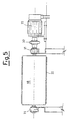
- figure 5 represents a side, partially sectional, view of the motor roll belonging to the salt collecting device of the previous figures.
Claims (10)
- A device for the collection of salt, comprising a series of conveyor belts (21,22) and a shovel (16) for the digging and collection of salt (30), characterized in that the above digging and collecting shovel (16) is associated with a supporting structure (13) which can be connected to a motor machine (11) by means of articulation mechanisms (35, 36, 15), wherein devices for regulating the operating position of the above digging and collecting shovel (16), operating by means of a signal (90) indicating a reference quota, are connected to the above digging and collecting shovel (16).
- The device according to claim 1, characterized in that the devices for regulating the operating position of the above digging and collecting shovel (16) comprise a laser receiver (12), which receives the above reference signal (90) from an infra-red source and communicates with an electro-hydraulic transducer (17) to activate the above articulation mechanisms (35, 36, 15).
- The device according to claim 2, characterized in that the above articulation mechanisms comprise a pair of moving arms (35, 36), each activated by an actuator (41).
- The device according to claim 3, characterized in that levers (15) are connected to the above pair of moving arms (35, 36), each lever being connected, in turn, to the above supporting structure (13) by means of a hinge (54) running inside a guide (55).
- The device according to claim 3, characterized in that the devices for regulating the operating position of the above digging and collecting shovel (16) comprise a pair of actuators (14, 64), each of which operating on respective rods (42, 62), hinged to the above supporting structure (13), so as to act thereon in a vertical direction.
- The device according to claim 5, characterized in that a respective wheel (37, 38) is connected to each of the above rods (42,62), hinged to the above supporting structure (13).
- The device, according to claim 1, characterized in that the above series of conveyor belts (21, 22) for salt (30) has an oblique loading belt (22), equipped with independent motorization, and a collection belt (21), on which the salt (30) collected from the shovel (16), is deposited.
- The device according to claim 2, characterized in that the above electro-hydraulic transducer (17) is assembled on the above motor machine (11).
- The device according to claim 1, characterized in that the above supporting structure (13) can be removed from the above motor machine (11).
- A device for the collection of salt, as substantially described and illustrated in the enclosed drawings.
Applications Claiming Priority (2)
| Application Number | Priority Date | Filing Date | Title |
|---|---|---|---|
| ITMI991001 | 1999-05-07 | ||
| ITMI991001 IT1312458B1 (en) | 1999-05-07 | 1999-05-07 | SALT COLLECTION DEVICE |
Publications (2)
| Publication Number | Publication Date |
|---|---|
| EP1050630A2 true EP1050630A2 (en) | 2000-11-08 |
| EP1050630A3 EP1050630A3 (en) | 2004-01-02 |
Family
ID=11382916
Family Applications (1)
| Application Number | Title | Priority Date | Filing Date |
|---|---|---|---|
| EP00108533A Withdrawn EP1050630A3 (en) | 1999-05-07 | 2000-04-19 | Salt-collecting device |
Country Status (2)
| Country | Link |
|---|---|
| EP (1) | EP1050630A3 (en) |
| IT (1) | IT1312458B1 (en) |
Cited By (2)
| Publication number | Priority date | Publication date | Assignee | Title |
|---|---|---|---|---|
| CN103103998A (en) * | 2013-02-26 | 2013-05-15 | 中冶建工集团有限公司 | Intelligent bulldozing method capable of controlling level foundation elevation randomly and automatically |
| CN114541498A (en) * | 2022-02-24 | 2022-05-27 | 谢文娟 | Portable construction ground shovel sand device |
Family Cites Families (5)
| Publication number | Priority date | Publication date | Assignee | Title |
|---|---|---|---|---|
| CH562930A5 (en) * | 1972-12-29 | 1975-06-13 | Eberhard Geb | Ground levelling machine with reference marks for survey - uses laser beam aligning for correcting ground levelling movement |
| CA1077893A (en) * | 1977-04-01 | 1980-05-20 | Canadian Mine Services Limited | Loading apparatus for mines |
| DE3412829A1 (en) * | 1984-04-05 | 1985-10-31 | Fried. Krupp Gmbh, 4300 Essen | FOURDERGUT-CHARGER |
| DE3509671C2 (en) * | 1985-03-18 | 1987-04-09 | Reinhard 5461 Windhagen Wirtgen | Sensor arrangement for controlling the milling depth setting of a surface milling cutter |
| JP3827764B2 (en) * | 1996-03-19 | 2006-09-27 | 株式会社トプコン | Laser light detection display for construction machinery |
-
1999
- 1999-05-07 IT ITMI991001 patent/IT1312458B1/en active
-
2000
- 2000-04-19 EP EP00108533A patent/EP1050630A3/en not_active Withdrawn
Cited By (2)
| Publication number | Priority date | Publication date | Assignee | Title |
|---|---|---|---|---|
| CN103103998A (en) * | 2013-02-26 | 2013-05-15 | 中冶建工集团有限公司 | Intelligent bulldozing method capable of controlling level foundation elevation randomly and automatically |
| CN114541498A (en) * | 2022-02-24 | 2022-05-27 | 谢文娟 | Portable construction ground shovel sand device |
Also Published As
| Publication number | Publication date |
|---|---|
| ITMI991001A1 (en) | 2000-11-07 |
| EP1050630A3 (en) | 2004-01-02 |
| IT1312458B1 (en) | 2002-04-17 |
Similar Documents
| Publication | Publication Date | Title |
|---|---|---|
| JP3968481B2 (en) | Seedling transplanter | |
| NO782543L (en) | LOAD DRAWER, PREFERREDLY FOR USE IN AGRICULTURE AND FORESTRY | |
| ITMI991001A1 (en) | SALT COLLECTION DEVICE | |
| JPH11225527A (en) | Peanut harvester | |
| EP0719495B1 (en) | Harvesting device | |
| US2855116A (en) | Vehicle mounted earth moving apparatus | |
| CN108738628A (en) | A kind of corm kind crop harvester | |
| GB2248539A (en) | "Soil lifting harvesters" | |
| JP2001128508A (en) | Potato transplanter | |
| JP2610436B2 (en) | Underground crop harvester | |
| JPS6230906Y2 (en) | ||
| JPH0123224Y2 (en) | ||
| JP4313471B2 (en) | Transplanting machine such as sputum | |
| JP3280842B2 (en) | Body height adjustment device for transplanter | |
| JP3422437B2 (en) | Transplant machine | |
| JP2002291313A (en) | Onion harvester | |
| JP6956676B2 (en) | Harvester | |
| JP4313479B2 (en) | Transplanting machine such as sputum | |
| JP3818622B2 (en) | Seed transplanter | |
| JPS59179004A (en) | Potato planter | |
| JPH10337105A (en) | Transplant machine | |
| RU1789602C (en) | Towed land leveller | |
| CS209364B1 (en) | Potato planter,suitable especially for slope works | |
| WO2005020662A1 (en) | Vegetable transplanter | |
| JPH0956222A (en) | Body height adjustment device for transplanter |
Legal Events
| Date | Code | Title | Description |
|---|---|---|---|
| PUAI | Public reference made under article 153(3) epc to a published international application that has entered the european phase |
Free format text: ORIGINAL CODE: 0009012 |
|
| AK | Designated contracting states |
Kind code of ref document: A2 Designated state(s): AT BE CH CY DE DK ES FI FR GB GR IE IT LI LU MC NL PT SE |
|
| AX | Request for extension of the european patent |
Free format text: AL PAYMENT 20000419;LT;LV;MK PAYMENT 20000419;RO;SI |
|
| PUAL | Search report despatched |
Free format text: ORIGINAL CODE: 0009013 |
|
| AK | Designated contracting states |
Kind code of ref document: A3 Designated state(s): AT BE CH CY DE DK ES FI FR GB GR IE IT LI LU MC NL PT SE |
|
| AX | Request for extension of the european patent |
Extension state: AL LT LV MK RO SI |
|
| AKX | Designation fees paid |
Designated state(s): AT BE CH CY DE DK ES FI FR GB GR IE IT LI LU MC NL PT SE |
|
| AXX | Extension fees paid |
Extension state: MK Payment date: 20000419 Extension state: AL Payment date: 20000419 |
|
| STAA | Information on the status of an ep patent application or granted ep patent |
Free format text: STATUS: THE APPLICATION IS DEEMED TO BE WITHDRAWN |
|
| 18D | Application deemed to be withdrawn |
Effective date: 20040703 |