EP1049270A2 - Apparatus and method for instantaneous reacquisition in a network system - Google Patents
Apparatus and method for instantaneous reacquisition in a network system Download PDFInfo
- Publication number
- EP1049270A2 EP1049270A2 EP00303650A EP00303650A EP1049270A2 EP 1049270 A2 EP1049270 A2 EP 1049270A2 EP 00303650 A EP00303650 A EP 00303650A EP 00303650 A EP00303650 A EP 00303650A EP 1049270 A2 EP1049270 A2 EP 1049270A2
- Authority
- EP
- European Patent Office
- Prior art keywords
- time
- ground station
- spread spectrum
- central node
- channel
- Prior art date
- Legal status (The legal status is an assumption and is not a legal conclusion. Google has not performed a legal analysis and makes no representation as to the accuracy of the status listed.)
- Granted
Links
Images



Classifications
-
- H—ELECTRICITY
- H04—ELECTRIC COMMUNICATION TECHNIQUE
- H04B—TRANSMISSION
- H04B7/00—Radio transmission systems, i.e. using radiation field
- H04B7/14—Relay systems
- H04B7/15—Active relay systems
- H04B7/185—Space-based or airborne stations; Stations for satellite systems
- H04B7/18502—Airborne stations
- H04B7/18504—Aircraft used as relay or high altitude atmospheric platform
Definitions
- the present invention relates to my co-pending U.S. Applications, Serial No. 107,209 filed 29 June 1998 for A Method for Dissemination of Multi-Sensor Products and U.S. Application , Serial No. 107,208 filed 29 June 1998 for an Adaptable and Controllable Multi-Channel Data Link.
- the present invention relates to communication data links of the type employed between an airborne platform or platforms and ground stations. More particularly, the present invention relates to a novel multi-channel data link where each channel contains a time of day spread spectrum waveform having means for independently advancing and retarding the time of day in each of the quadrature channels to enable instantaneous reacquisition of a ground station after an outage has occurred.
- airborne surveillance platforms are used to capture optical images, infrared images and/or radar images and to process the sensed image information into a digital format and then communicate this image information to plural ground stations over a data link using secure spread spectrum modulated waveforms.
- the ground station loses its spread spectrum synchronization or lock of the down link signal.
- the airborne platform also loses its synchronization or lock on the up link signal from the ground station. Any attempt by the airborne platform to advance or retard its down link signal to aid the ground station to reacquire the down link signal will cause the other ground stations to lose their lock or synchronization on their down link signals.
- TDMA Time Division Multiple Access
- multi-channel in-phase (I) and quadrature phase (Q) multi-channel transmitters were known, but were employed to enhance the amount of power received at a receiver.
- Such systems are explained in my USPN 5,559,788 which is incorporated by reference herein.
- the power and data rate of the in-phase and quadrature channels were adjusted to overcome jamming of one ground station which could cause an outage of the network system or a reduction in the data rate of the entire network system.
- a central node or airborne station with a multi-channel transmitter/receiver capable of transmitting quadrature phase spread spectrum signals both of which contain data.
- One channel is maintained as a master channel which provides a master time of day clock for the network system and the other channel is employed as an adjustable time of day channel.
- the airborne station calculates the propagation time to the ground station and shifts the adjustable channel to transmit a spread spectrum data signal which will arrive in synchronization with the time of day clock in the ground station that has the outage.
- the transmitted data signal is instantaneously reacquired by the ground station and the data accompanying the down link transmission is employed to resynchronize the ground station receiver/transmitter with the master clock in the airborne receiver/transmitter.
- FIG. 1 showing a prior art single channel data link network system 10 comprising a plurality of ground stations 11 to 12 and a single central node or airborne station 13.
- the airborne station 13 has some blockage 14 or condition which prevents its down link signal from reaching the ground station 12. This blockage or outage can be caused by terrain masking or aircraft shadowing or other reasons.
- the ground station is not capable of communicating with the airborne station 13.
- the airborne station 13 at the time of outage with ground station 12 is still capable of communicating with ground station 11.
- the airborne or central node station 13 has moved to a new position shown by phantom lines at block 13' it has a line of sight or communication ability with both ground station 11 and ground station 12.
- the ground station 12 has lost its synchronization with the master time of day clock which is part of the control system of the airborne station 13, 13'.
- the master time of day (t) in the airborne station 13 was changed during its propagation time T1 and T2. It will be noted that the propagation times T1 and T2 differ substantially and the time of arrival of the signal at ground station 11 and ground station 12 before outage is shown as t plus T2 and t plus T1, respectively. After the airborne station has moved to its new position shown at block 13' the new time of day arrival of the signals has changed to t plus T2' and t plus T1', respectively.
- any attempt of the airborne station 13 to correct its single channel time of day clock to aid in the acquisition of ground station 12 after outage will automatically cause the ground station 11 to see a changing time of day signal which will cause it to lose lock or synchronization.
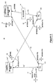
- FIG. 2 showing a schematic block diagram of a surveillance system 20 having a plurality of ground stations and a single central node 13A similar to that described in Figure 1.
- the transmitter/receiver and control systems in the central node 13A and 13A' have been modified to transmit dual or multi-channel signals and the ground stations 11A and 12A have transmitter/receivers that have been modified to receive the multi-channel or dual channel signals.
- a diagrammatic signal 15 is shown having a vertical vector illustrating the master time of day t and a horizontal vector illustrating an adjustable time of day t which are in quadrature phase relationship with each other so as to avoid cross-channel interference.
- the time of day of the signal shown as T1 leaving the airborne station 13A is illustrated by the signal 15 which is also applied to the same signal transmitted to receiver 11A but with a propagation time T2.
- the time of arrival of the dual channel signal from central node or airborne station 13A at ground station 12A is shown as a multi-channel signal having a master time of day t plus T1 and an adjustable time of day signal t plus T1 at the time of outage caused by the obstruction 14.
- the same signal 15 is shown at time of arrival at ground station 11A as having a master time of day t plus T2 and an adjustable time of day t plus T2 at the time of outage.
- the obstruction 14 is no longer in the line of sight and has been removed.
- the ground station 11A has continued its communication with its up link and down link signals with the airborne station 13A without interruption.
- the down link signal having a propagation time T2' is arriving as a complex signal or dual channel signal shown by the vectors 17.
- the down link signal at the time of transmission from the airborne station 13A' is shown at the vector 18 comprising a master time of day clock t and an adjustable time of day clock t plus T1 minus T1' after adjustment.
- the airborne station 13A' desires to transmit an adjusted signal that will arrive in synchronization with the adjusted time of day clock shown as t plus T1 at ground station 12A. This is accomplished by adjusting the adjustable time of day clock at the airborne station 13A to t plus T1 minus T1' and the adjusted signal arrives at the ground station 12A such that the T1' propagation time cancels out and the ground station 12A receives its signals as if the airborne station was still at the outage position 13A.
- the ground station 12A correlates its local time of day with the adjusted down link signal. Station 12A then uses this course lock correlation to perform precise time of day lock-on such that any residual time difference between the ground stations local time of day and the received adjusted time of day are removed. It is now necessary for the ground station 12A to inform the central node or airborne station 13A that it has acquired synchronization. Ground station 12A employs the down link information supplied by the airborne station to adjust its own clock so that it is synchronized to the master time of day (t) in the airborne platform 13A' as will be explained in greater detail hereinafter. It will be explained that when this adjustment is complete that the factor T1 minus T1' will be eliminated from the master clock equation and both channels will be in synchronization with the master time of day clock.
- ground station 11A was tracking the master time of day and continues tracking the master time of day while this adjustment has been transpiring. Thus, it maintains its own synchronization and its time of day clock has not been changed.
- waveform Figure 3A showing a series of time of day epochs 21 through 24 that are occurring at the airborne station 13A.
- these epochs or time of day slots may be used for time division multiple access time slots.
- FIG. 3B shows the delay in time shifted time epoch slots 21 through 24 at the time of arrival at the ground station 12A before any outage has occurred.
- time slot 25 which occurs at the ground station 12A at the time of its up link transmission.
- the time slot 25 is transmitted in time prior to the occurrence of its time slot allocated by the receiver but at the time of arrival at the airborne station 13A, it will synchronize with and occur at time slot 22. It will be understood that data is usually transmitted during this time slot 25 for arrival at the airborne station during time slot 22.
- FIG. 3D showing the composite for four ground stations up link time slots at the time of arrival at the airborne station 13A.
- the four stations have their transmitted data arriving at the airborne station in perfect synchronization with the epochs 21 through 24.
- each of the plurality of ground stations GS1 to GSN has its own unique time slot and the airborne station 13A has a unique epoch or time slot for arrival of the information in the ground station's time slot which occurs in synchronism with the occurrence of the time slots 21 through 24 shown as data 21A to 24A.
- FIG. 4A showing a time slot N(22B) at its time of arrival at the airborne station 13A'.
- the airborne station 13A has moved to a new position 13A' causing a displacement in time shown as "ABS moved” which lengthens the previous propagation time shown as T1.
- the airborne station 13A' knows its old position and its new position and knows the position of the ground station 12A, thus is able to calculate the propagation time T1'.
- the difference between T1' minus Tl is the factor "ABS moved”.
- the airborne station 13A' is able to make the adjustment time of day calculation t plus T1 discussed hereinbefore so that the signal transmitted to the ground station will be synchronized with the time of day clock in the ground station 12A at the time of outage.
- Block 31 shows that the control in the airborne station 13A starts with the synchronization of the network 20.
- Block 32 shows that the ABS control causes the transmittal of a waveform master time of day (t) and adjusted time of day (t) to all ground stations.
- the block 33 shows that the airborne station next polls the status of the up link signals from the ground stations.
- the control in the ABS platform makes the logical decision whether any of the ground stations have an outage by looking for an up link signal from each and every station. If all ground stations respond with status, then there is no outage as shown on line 35 and the logic returns to block 32.
- the ground station GS x has an outage as shown at block 36.
- the control in the ABS saves the time T1 or propagation time to the ground station GS x at the time of outage.
- the control in the ABS looks for an up link signal from the ground station GS x as shown in block 37.
- the airborne station saves the new propagation time T1'.
- the control in the airborne station modifies the down link signal adjusted time of day (which is equal to t plus T1 minus Tl') and transmits T1 minus T1' data to the ground station GS x .
- the ground station GS x automatically and instantaneously syncs on the adjusted time of day signal and the ground station GS x adjusts its own master time of day clock by T1 minus T1'.
- the ground station GS x sends an up link signal that its master time of day has been resynced as shown at block 40.
- the airborne station receives the acknowledgement and ceases the time shift Tl minus T1' in the adjusted time of day channel as shown in block 41.
- the control signal on line 47 returns the control logic to block 32.
Landscapes
- Engineering & Computer Science (AREA)
- Signal Processing (AREA)
- Astronomy & Astrophysics (AREA)
- Aviation & Aerospace Engineering (AREA)
- General Physics & Mathematics (AREA)
- Computer Networks & Wireless Communication (AREA)
- Physics & Mathematics (AREA)
- Time-Division Multiplex Systems (AREA)
- Mobile Radio Communication Systems (AREA)
- Small-Scale Networks (AREA)
- Synchronisation In Digital Transmission Systems (AREA)
- Radar Systems Or Details Thereof (AREA)
- Circuits Of Receivers In General (AREA)
Abstract
Description
Claims (12)
- Apparatus in a data link network system of the type having a central node and a plurality of ground stations each having transmitter/receivers for maintaining spread spectrum communications on the network, comprising:a transmitter in said central node having a multi-channel transmitter for transmitting quadrature and in phase spread spectrum data signals,one of said multi-channels providing a fixed master time of day clock for said data link network system,the other of said multi-channels providing an adjustable time of day clock relative to said master time of day clock,control means in said central node for sensing an outage between said central node and a ground station,said control means in said central node for calculating the propagation time T1 to said ground station,said control means in said central node for adjusting the timing of one of said spread spectrum signals to be transmitted relative to said master clock so that the adjusted signal is synchronized with the spread spectrum receiver in said ground station, andmeans in said ground station receiver for instantaneously reacquiring the transmitted adjusted spread spectrum signal transmitted by said central node to said ground station.
- Apparatus as set forth in Claim 1 wherein the ground station receiver comprises means for receiving data indicative of said propagation time Tl and for calculating a ground station clock time that is resynchronized with said master clock in said central node.
- Apparatus as set forth in Claim 2 wherein the ground station receiver/transmitter comprises means for transmitting data to said central node indicative of its network status including that reacquisition is established.
- Apparatus as set forth in Claim 3 wherein said central node receiver/transmitter comprises means for receiving status data from said ground station and for readjusting said adjustable channel to the same time relationship with said master clock in said central node.
- Apparatus as set forth in Claim 1 wherein said control means in said central node comprises means for determining the status of all of said ground receivers and for reestablishing acquisition of any ground station after an outage is detected.
- Apparatus as set forth in Claim 5 wherein said control means further comprises means for allocating power and data rate of the spread spectrum signals in said multi-channels when all ground stations are reacquired and no outage exists.
- A method of reacquiring synchronization between a multi-channel central node receiver/transmitter and a receiver/transmitter of a ground station after an outage, comprising the steps of:sensing at the central node receiver/ transmitter that an outage has occurred between a ground station and the central node,sensing at the central node when the outage has been removed and an up link data signal can be received,determining at the central node the propagation time required to transmit spread spectrum signals to said ground station,adjusting the relative time of the spread spectrum signals in an in phase adjustable channel of said multi-channel receiver/transmitter while maintaining the master channel with the master time of day clock spread spectrum signals,transmitting said adjusted spread spectrum signals to said ground station adjusted to arrive in synchronization with the spread spectrum clock signals in said ground station receiver,instantaneously reacquiring said adjusted spread spectrum signal and data accompanying said adjusted signal, andemploying said accompanying data to reset the relative time of said spread spectrum clock signals in said ground station receiver so that subsequent spread spectrum signals from said master channel are received in synchronization with the spread spectrum receiver in said ground station.
- The method as set forth in Claim 7 which further includes the step of transmitting from said ground station to said central node a status signal that is synchronized to arrive at said central node at a predetermined time.
- The method as set forth in Claim 8 wherein said predetermined time comprises a unique time division multiple access time slot.
- The method as set forth in Claim 7 wherein said step of transmitting said adjusted spread spectrum signals to said ground station comprises transmitting said adjusted signals until an acknowledgement signal is received from said ground station.
- The method as set forth in Claim 10 which further includes ceasing transmittal of said adjusted signals to said ground station, and
returning said adjusted time of said spread spectrum signals in said adjustable channel to synchronization with the master time of day clock signals to said master channel. - The method as set forth in Claim 11 which further includes the step of controlling the power and data rate of said multi-channels independently of each other.
Applications Claiming Priority (2)
| Application Number | Priority Date | Filing Date | Title |
|---|---|---|---|
| US301950 | 1999-04-29 | ||
| US09/301,950 US6501808B1 (en) | 1999-04-29 | 1999-04-29 | Apparatus and method for instantaneous reacquisition in a network system |
Publications (3)
| Publication Number | Publication Date |
|---|---|
| EP1049270A2 true EP1049270A2 (en) | 2000-11-02 |
| EP1049270A3 EP1049270A3 (en) | 2003-08-27 |
| EP1049270B1 EP1049270B1 (en) | 2006-10-18 |
Family
ID=23165611
Family Applications (1)
| Application Number | Title | Priority Date | Filing Date |
|---|---|---|---|
| EP00303650A Expired - Lifetime EP1049270B1 (en) | 1999-04-29 | 2000-04-28 | Apparatus and method for instantaneous reacquisition in a network system |
Country Status (4)
| Country | Link |
|---|---|
| US (1) | US6501808B1 (en) |
| EP (1) | EP1049270B1 (en) |
| AT (1) | ATE343261T1 (en) |
| DE (1) | DE60031324T2 (en) |
Cited By (2)
| Publication number | Priority date | Publication date | Assignee | Title |
|---|---|---|---|---|
| US7821420B2 (en) | 2002-12-23 | 2010-10-26 | Renishaw Plc | Signal transmission system for a measurement device |
| US8014378B1 (en) | 2003-10-23 | 2011-09-06 | Itt Manufacturing Enterprise, Inc. | Method and apparatus for automatic control of time-of-day synchronization and merging of networks |
Families Citing this family (1)
| Publication number | Priority date | Publication date | Assignee | Title |
|---|---|---|---|---|
| US7024340B2 (en) * | 2004-03-02 | 2006-04-04 | Northrop Grumman Corporation | Automatic collection manager |
Family Cites Families (8)
| Publication number | Priority date | Publication date | Assignee | Title |
|---|---|---|---|---|
| US3778715A (en) * | 1971-08-11 | 1973-12-11 | Communications Satellite Corp | Tdma satellite communications system with rapid automatic re-entry following brief outages of earth station equipment |
| US4882739A (en) * | 1988-01-26 | 1989-11-21 | Computer Sports Medicine, Inc. | Method for adjusting clocks of multiple data processors to a common time base |
| US4893318A (en) * | 1988-01-26 | 1990-01-09 | Computer Sports Medicine, Inc. | Method for referencing multiple data processors to a common time reference |
| US5239671A (en) * | 1990-11-13 | 1993-08-24 | Pagemart, Inc. | Simulcast satellite paging system with provision for signal interruption |
| US5261118A (en) * | 1991-10-04 | 1993-11-09 | Motorola, Inc. | Simulcast synchronization and equalization system and method therefor |
| US5257404A (en) * | 1991-10-04 | 1993-10-26 | Motorola, Inc. | Simulcast synchronization and equalization system and method therefor |
| US5280629A (en) * | 1991-12-06 | 1994-01-18 | Motorola, Inc. | Technique for measuring channel delay |
| US5559788A (en) * | 1994-12-29 | 1996-09-24 | Unisys Corporation | Multiple channel quadrature communication system and method |
-
1999
- 1999-04-29 US US09/301,950 patent/US6501808B1/en not_active Expired - Lifetime
-
2000
- 2000-04-28 AT AT00303650T patent/ATE343261T1/en not_active IP Right Cessation
- 2000-04-28 DE DE60031324T patent/DE60031324T2/en not_active Expired - Lifetime
- 2000-04-28 EP EP00303650A patent/EP1049270B1/en not_active Expired - Lifetime
Cited By (3)
| Publication number | Priority date | Publication date | Assignee | Title |
|---|---|---|---|---|
| US7821420B2 (en) | 2002-12-23 | 2010-10-26 | Renishaw Plc | Signal transmission system for a measurement device |
| US9140547B2 (en) | 2002-12-23 | 2015-09-22 | Renishaw Plc | Signal transmission system for a measurement device |
| US8014378B1 (en) | 2003-10-23 | 2011-09-06 | Itt Manufacturing Enterprise, Inc. | Method and apparatus for automatic control of time-of-day synchronization and merging of networks |
Also Published As
| Publication number | Publication date |
|---|---|
| US6501808B1 (en) | 2002-12-31 |
| EP1049270B1 (en) | 2006-10-18 |
| DE60031324D1 (en) | 2006-11-30 |
| EP1049270A3 (en) | 2003-08-27 |
| DE60031324T2 (en) | 2007-05-31 |
| ATE343261T1 (en) | 2006-11-15 |
Similar Documents
| Publication | Publication Date | Title |
|---|---|---|
| JP2974980B2 (en) | Method and apparatus for synchronizing communications in a satellite-based telecommunications system | |
| US4577316A (en) | Synchronization system for a regenerative subtransponder satellite communication system | |
| US5119504A (en) | Position aided subscriber unit for a satellite cellular system | |
| US9247513B2 (en) | Base station synchronization | |
| CA2343096C (en) | Method of and apparatus for time synchronization in a communication system | |
| US20190199428A1 (en) | Timing synchronization for a beam hopping satellite | |
| WO2019133176A1 (en) | Timing synchronization with a modified dvb-s2x waveform for a beam hopping satellite | |
| CA1227845A (en) | Multipoint data communications | |
| US6845085B1 (en) | Synchronization method for a processing communication satellite | |
| AU6223100A (en) | Method and apparatus for sequentially synchronized network | |
| EP1717970B1 (en) | Radio transceiver and radio transmitting method | |
| US3654395A (en) | Synchronization of tdma space division satellite system | |
| AU2017279481A1 (en) | Synchronous waveform clock synchronization without a system controller | |
| US5309439A (en) | TDMA system with a virtual reference | |
| EP1049270B1 (en) | Apparatus and method for instantaneous reacquisition in a network system | |
| WO1999056409A1 (en) | Tdma system timer for maintaining timing to multiple satellite simultaneously | |
| US8218700B2 (en) | Method for synchronisation and control in wireless communication systems | |
| JPH1075205A (en) | Mobile communication device | |
| Vachula et al. | Synchronous Waveform Clock Synchronization Without a System Controller | |
| CA2317129A1 (en) | Synchronization method for a processing communication satellite | |
| JPH0821918B2 (en) | Transmission timing acquisition method | |
| CN113382467A (en) | Uplink sending timing adjusting method | |
| JP2731640B2 (en) | TDMA frame synchronization method between multiple radio base stations | |
| JPH01240025A (en) | Concentrating distributing system |
Legal Events
| Date | Code | Title | Description |
|---|---|---|---|
| PUAI | Public reference made under article 153(3) epc to a published international application that has entered the european phase |
Free format text: ORIGINAL CODE: 0009012 |
|
| AK | Designated contracting states |
Kind code of ref document: A2 Designated state(s): AT BE CH CY DE DK ES FI FR GB GR IE IT LI LU MC NL PT SE |
|
| AX | Request for extension of the european patent |
Free format text: AL;LT;LV;MK;RO;SI |
|
| PUAL | Search report despatched |
Free format text: ORIGINAL CODE: 0009013 |
|
| AK | Designated contracting states |
Designated state(s): AT BE CH CY DE DK ES FI FR GB GR IE IT LI LU MC NL PT SE |
|
| AX | Request for extension of the european patent |
Extension state: AL LT LV MK RO SI |
|
| RIC1 | Information provided on ipc code assigned before grant |
Ipc: 7H 04B 7/185 A Ipc: 7H 04B 7/212 B |
|
| 17P | Request for examination filed |
Effective date: 20031031 |
|
| AKX | Designation fees paid |
Designated state(s): AT BE CH CY DE DK ES FI FR GB GR IE IT LI LU MC NL PT SE |
|
| 17Q | First examination report despatched |
Effective date: 20050131 |
|
| GRAP | Despatch of communication of intention to grant a patent |
Free format text: ORIGINAL CODE: EPIDOSNIGR1 |
|
| GRAS | Grant fee paid |
Free format text: ORIGINAL CODE: EPIDOSNIGR3 |
|
| GRAA | (expected) grant |
Free format text: ORIGINAL CODE: 0009210 |
|
| AK | Designated contracting states |
Kind code of ref document: B1 Designated state(s): AT BE CH CY DE DK ES FI FR GB GR IE IT LI LU MC NL PT SE |
|
| PG25 | Lapsed in a contracting state [announced via postgrant information from national office to epo] |
Ref country code: LI Free format text: LAPSE BECAUSE OF FAILURE TO SUBMIT A TRANSLATION OF THE DESCRIPTION OR TO PAY THE FEE WITHIN THE PRESCRIBED TIME-LIMIT Effective date: 20061018 Ref country code: NL Free format text: LAPSE BECAUSE OF FAILURE TO SUBMIT A TRANSLATION OF THE DESCRIPTION OR TO PAY THE FEE WITHIN THE PRESCRIBED TIME-LIMIT Effective date: 20061018 Ref country code: AT Free format text: LAPSE BECAUSE OF FAILURE TO SUBMIT A TRANSLATION OF THE DESCRIPTION OR TO PAY THE FEE WITHIN THE PRESCRIBED TIME-LIMIT Effective date: 20061018 Ref country code: FI Free format text: LAPSE BECAUSE OF FAILURE TO SUBMIT A TRANSLATION OF THE DESCRIPTION OR TO PAY THE FEE WITHIN THE PRESCRIBED TIME-LIMIT Effective date: 20061018 Ref country code: CH Free format text: LAPSE BECAUSE OF FAILURE TO SUBMIT A TRANSLATION OF THE DESCRIPTION OR TO PAY THE FEE WITHIN THE PRESCRIBED TIME-LIMIT Effective date: 20061018 Ref country code: BE Free format text: LAPSE BECAUSE OF FAILURE TO SUBMIT A TRANSLATION OF THE DESCRIPTION OR TO PAY THE FEE WITHIN THE PRESCRIBED TIME-LIMIT Effective date: 20061018 Ref country code: IT Free format text: LAPSE BECAUSE OF FAILURE TO SUBMIT A TRANSLATION OF THE DESCRIPTION OR TO PAY THE FEE WITHIN THE PRESCRIBED TIME-LIMIT;WARNING: LAPSES OF ITALIAN PATENTS WITH EFFECTIVE DATE BEFORE 2007 MAY HAVE OCCURRED AT ANY TIME BEFORE 2007. THE CORRECT EFFECTIVE DATE MAY BE DIFFERENT FROM THE ONE RECORDED. Effective date: 20061018 |
|
| REG | Reference to a national code |
Ref country code: GB Ref legal event code: FG4D |
|
| REG | Reference to a national code |
Ref country code: CH Ref legal event code: EP Ref country code: IE Ref legal event code: FG4D |
|
| REG | Reference to a national code |
Ref country code: SE Ref legal event code: TRGR |
|
| REF | Corresponds to: |
Ref document number: 60031324 Country of ref document: DE Date of ref document: 20061130 Kind code of ref document: P |
|
| PG25 | Lapsed in a contracting state [announced via postgrant information from national office to epo] |
Ref country code: DK Free format text: LAPSE BECAUSE OF FAILURE TO SUBMIT A TRANSLATION OF THE DESCRIPTION OR TO PAY THE FEE WITHIN THE PRESCRIBED TIME-LIMIT Effective date: 20070118 |
|
| PG25 | Lapsed in a contracting state [announced via postgrant information from national office to epo] |
Ref country code: ES Free format text: LAPSE BECAUSE OF FAILURE TO SUBMIT A TRANSLATION OF THE DESCRIPTION OR TO PAY THE FEE WITHIN THE PRESCRIBED TIME-LIMIT Effective date: 20070129 |
|
| PG25 | Lapsed in a contracting state [announced via postgrant information from national office to epo] |
Ref country code: PT Free format text: LAPSE BECAUSE OF FAILURE TO SUBMIT A TRANSLATION OF THE DESCRIPTION OR TO PAY THE FEE WITHIN THE PRESCRIBED TIME-LIMIT Effective date: 20070319 |
|
| NLV1 | Nl: lapsed or annulled due to failure to fulfill the requirements of art. 29p and 29m of the patents act | ||
| REG | Reference to a national code |
Ref country code: CH Ref legal event code: PL |
|
| ET | Fr: translation filed | ||
| PLBE | No opposition filed within time limit |
Free format text: ORIGINAL CODE: 0009261 |
|
| STAA | Information on the status of an ep patent application or granted ep patent |
Free format text: STATUS: NO OPPOSITION FILED WITHIN TIME LIMIT |
|
| 26N | No opposition filed |
Effective date: 20070719 |
|
| PG25 | Lapsed in a contracting state [announced via postgrant information from national office to epo] |
Ref country code: GR Free format text: LAPSE BECAUSE OF FAILURE TO SUBMIT A TRANSLATION OF THE DESCRIPTION OR TO PAY THE FEE WITHIN THE PRESCRIBED TIME-LIMIT Effective date: 20070119 |
|
| PG25 | Lapsed in a contracting state [announced via postgrant information from national office to epo] |
Ref country code: IE Free format text: LAPSE BECAUSE OF NON-PAYMENT OF DUE FEES Effective date: 20070430 |
|
| PG25 | Lapsed in a contracting state [announced via postgrant information from national office to epo] |
Ref country code: MC Free format text: LAPSE BECAUSE OF NON-PAYMENT OF DUE FEES Effective date: 20070430 |
|
| PG25 | Lapsed in a contracting state [announced via postgrant information from national office to epo] |
Ref country code: LU Free format text: LAPSE BECAUSE OF NON-PAYMENT OF DUE FEES Effective date: 20070428 Ref country code: CY Free format text: LAPSE BECAUSE OF FAILURE TO SUBMIT A TRANSLATION OF THE DESCRIPTION OR TO PAY THE FEE WITHIN THE PRESCRIBED TIME-LIMIT Effective date: 20061018 |
|
| PGFP | Annual fee paid to national office [announced via postgrant information from national office to epo] |
Ref country code: FR Payment date: 20100506 Year of fee payment: 11 |
|
| PGFP | Annual fee paid to national office [announced via postgrant information from national office to epo] |
Ref country code: IT Payment date: 20100424 Year of fee payment: 11 |
|
| PGFP | Annual fee paid to national office [announced via postgrant information from national office to epo] |
Ref country code: GB Payment date: 20100420 Year of fee payment: 11 Ref country code: SE Payment date: 20100415 Year of fee payment: 11 |
|
| REG | Reference to a national code |
Ref country code: GB Ref legal event code: 732E Free format text: REGISTERED BETWEEN 20110428 AND 20110504 |
|
| REG | Reference to a national code |
Ref country code: SE Ref legal event code: EUG |
|
| GBPC | Gb: european patent ceased through non-payment of renewal fee |
Effective date: 20110428 |
|
| REG | Reference to a national code |
Ref country code: FR Ref legal event code: ST Effective date: 20111230 |
|
| PG25 | Lapsed in a contracting state [announced via postgrant information from national office to epo] |
Ref country code: FR Free format text: LAPSE BECAUSE OF NON-PAYMENT OF DUE FEES Effective date: 20110502 |
|
| PG25 | Lapsed in a contracting state [announced via postgrant information from national office to epo] |
Ref country code: GB Free format text: LAPSE BECAUSE OF NON-PAYMENT OF DUE FEES Effective date: 20110428 Ref country code: IT Free format text: LAPSE BECAUSE OF NON-PAYMENT OF DUE FEES Effective date: 20110428 |
|
| REG | Reference to a national code |
Ref country code: FR Ref legal event code: TP Owner name: NORTHROP GRUMMAN SYSTEMS CORPORATION, US Effective date: 20120314 |
|
| REG | Reference to a national code |
Ref country code: DE Ref legal event code: R081 Ref document number: 60031324 Country of ref document: DE Owner name: NORTHROP GRUMMAN SYSTEMS CORPORATION (N.D.GES., US Free format text: FORMER OWNER: NORTHROP GRUMMAN CORP., LOS ANGELES, US Effective date: 20130205 Ref country code: DE Ref legal event code: R081 Ref document number: 60031324 Country of ref document: DE Owner name: NORTHROP GRUMMAN SYSTEMS CORPORATION (N.D.GES., US Free format text: FORMER OWNER: NORTHROP GRUMMAN CORP., LOS ANGELES, CALIF., US Effective date: 20130205 |
|
| PG25 | Lapsed in a contracting state [announced via postgrant information from national office to epo] |
Ref country code: SE Free format text: LAPSE BECAUSE OF NON-PAYMENT OF DUE FEES Effective date: 20110429 |
|
| PGFP | Annual fee paid to national office [announced via postgrant information from national office to epo] |
Ref country code: DE Payment date: 20190418 Year of fee payment: 20 |
|
| REG | Reference to a national code |
Ref country code: DE Ref legal event code: R071 Ref document number: 60031324 Country of ref document: DE |