EP1049220A1 - Laser à gamme de température de fonctionnement étendue - Google Patents
Laser à gamme de température de fonctionnement étendue Download PDFInfo
- Publication number
- EP1049220A1 EP1049220A1 EP00401137A EP00401137A EP1049220A1 EP 1049220 A1 EP1049220 A1 EP 1049220A1 EP 00401137 A EP00401137 A EP 00401137A EP 00401137 A EP00401137 A EP 00401137A EP 1049220 A1 EP1049220 A1 EP 1049220A1
- Authority
- EP
- European Patent Office
- Prior art keywords
- wavelength
- laser
- value
- fiber
- reflection
- Prior art date
- Legal status (The legal status is an assumption and is not a legal conclusion. Google has not performed a legal analysis and makes no representation as to the accuracy of the status listed.)
- Granted
Links
- 239000000835 fiber Substances 0.000 claims abstract description 39
- 230000003287 optical effect Effects 0.000 claims abstract description 13
- 230000008878 coupling Effects 0.000 claims abstract description 11
- 238000010168 coupling process Methods 0.000 claims abstract description 11
- 238000005859 coupling reaction Methods 0.000 claims abstract description 11
- 239000013307 optical fiber Substances 0.000 claims abstract description 9
- 230000001747 exhibiting effect Effects 0.000 claims 1
- 230000000694 effects Effects 0.000 description 3
- 238000005086 pumping Methods 0.000 description 3
- 230000005540 biological transmission Effects 0.000 description 2
- 238000012512 characterization method Methods 0.000 description 2
- 238000001228 spectrum Methods 0.000 description 2
- 229910052691 Erbium Inorganic materials 0.000 description 1
- 229910000530 Gallium indium arsenide Inorganic materials 0.000 description 1
- 238000010586 diagram Methods 0.000 description 1
- 238000006073 displacement reaction Methods 0.000 description 1
- 238000000295 emission spectrum Methods 0.000 description 1
- UYAHIZSMUZPPFV-UHFFFAOYSA-N erbium Chemical compound [Er] UYAHIZSMUZPPFV-UHFFFAOYSA-N 0.000 description 1
- 239000004065 semiconductor Substances 0.000 description 1
Images

Classifications
-
- H—ELECTRICITY
- H01—ELECTRIC ELEMENTS
- H01S—DEVICES USING THE PROCESS OF LIGHT AMPLIFICATION BY STIMULATED EMISSION OF RADIATION [LASER] TO AMPLIFY OR GENERATE LIGHT; DEVICES USING STIMULATED EMISSION OF ELECTROMAGNETIC RADIATION IN WAVE RANGES OTHER THAN OPTICAL
- H01S5/00—Semiconductor lasers
- H01S5/10—Construction or shape of the optical resonator, e.g. extended or external cavity, coupled cavities, bent-guide, varying width, thickness or composition of the active region
- H01S5/14—External cavity lasers
- H01S5/146—External cavity lasers using a fiber as external cavity
-
- H—ELECTRICITY
- H01—ELECTRIC ELEMENTS
- H01S—DEVICES USING THE PROCESS OF LIGHT AMPLIFICATION BY STIMULATED EMISSION OF RADIATION [LASER] TO AMPLIFY OR GENERATE LIGHT; DEVICES USING STIMULATED EMISSION OF ELECTROMAGNETIC RADIATION IN WAVE RANGES OTHER THAN OPTICAL
- H01S5/00—Semiconductor lasers
- H01S5/10—Construction or shape of the optical resonator, e.g. extended or external cavity, coupled cavities, bent-guide, varying width, thickness or composition of the active region
- H01S5/12—Construction or shape of the optical resonator, e.g. extended or external cavity, coupled cavities, bent-guide, varying width, thickness or composition of the active region the resonator having a periodic structure, e.g. in distributed feedback [DFB] lasers
- H01S5/1221—Detuning between Bragg wavelength and gain maximum
Definitions
- the invention relates to the field of lasers with quantum wells comprising a means of reflection outside the laser cavity.
- the exact effect is function of parameters such as the value of the coefficient of reflection of the Bragg grating of the fiber, its bandwidth, the central wavelength of the network compared to the laser, the value of the optical distance between the laser and the network, and value of the current injected into the laser.
- the central wavelength of the Bragg grating is contained within a 10 nm band around the laser wavelength and the coefficient of reflection of network 34 has a value similar to that of the exit face 27 of the laser 26.
- the width of the reflected strip by the network 34 and its reflection coefficient are such as the return to the laser cavity due to the face of output, is greater than the return due to network 34.
- the network 34 acts as a disturbance of the emission spectrum of the laser diode 26, which has for effect of widening the emission band and thus making the diode less sensitive to disturbances due to changes in temperature or injected currents.
- network 34 has a peak of reflection which is 1 or 2 nm from the length wave of the diode, a reflection coefficient of 3%, which considering the coupling between the network and the diode leads to a return coefficient to the diode 1.08%.
- a pumping laser 13 an amplifier laser 12 also used for perform optical transmissions.
- This laser 12 is stabilized to avoid length fluctuations wave emitted, caused by stray reflections from the amplifier laser 12, by means of a fiber network 14.
- the inventors establish that the pumping laser 13 is stabilized if the coefficient of reflection of the network 14 is between 5 and 43 dB.
- the invention relates to a quantum well laser like those described in the two documents mentioned above, but capable of operating without special precautions in a temperature range between two distant limit temperatures each other by about 100 °, especially in the temperature range between - 20 ° C and + 70 ° C. It should first of all be understood that operate between -20 ° C and + 70 ° C. is not the same thing that widen the operating band so to have an output wavelength band independent of reasonable fluctuations in the operating temperature, for example in a temperature range fluctuating from 5 to 6 ° around a nominal operating temperature.
- the invention differs from the prior art in one important characteristic, however.
- the inventors have observed that, at a given temperature, the gain curve of the cavity as a function of the wavelength, presents in the direction of increasing wavelengths, a positive slope, a maximum for a length d wave ⁇ max then a negative slope.
- the positive slope has a slope coefficient which is much lower than the slope coefficient which follows the maximum.
- the condition that the gain of the cavity is equal to the losses of the cavity must be satisfied for the wavelength of the Bragg grating over the entire temperature range. of the fiber, despite the deformations brought to the gain curve of the cavity as a function of the wavelength, by the temperature variations.
- the inventors have found that it is sufficient that at the median temperature of the operating range the reflection wavelength of the fiber network has a value which is at least 10 less nm at the value of the wavelength ⁇ max giving maximum gain to the cavity.
- the difference to be expected is 15 plus or minus 5 nm. The fact of being placed at a value of wavelength being situated at a value of approximately 15 nm before this maximum, makes it possible to satisfy for a wide range of temperatures the threshold condition according to which the gain is equal to the losses, at the network wavelength.
- the energy received by the cavity laser in return from the network on fiber is greater than the energy received in return by the exit face of the laser.
- This functional characterization can be specified by a structural characterization defining a relationship linking the coefficients of the laser exit face and reflection coefficient of the network.
- the product of the coefficient of fiber network reflection by the square of loss coefficient due to the coupling between the fiber and the laser is greater than the reflection coefficient of the exit face of the cavity. In this way the energy received in return from the fiber network cannot no longer be seen as a widening disturbance the output optical spectrum.
- the value of the length wave reflected by the grating determines the value of the laser output wavelength. In a known way the value of the wavelength ⁇ reflected by the fiber network varies much less with the temperature than does the cavity. The result that with this configuration the optical system constituted by the laser, the fiber, and the means of coupling is able to operate with less dependence local temperature variations.
- the value of the coefficient of network reflection is more than 10 times greater than reflection coefficient of the laser output face.
- Figure 1 shows schematically and known as a laser cavity 1 arranged so that the emitted laser beam is directed by means focusing optics 2, in an optical fiber 5 comprising in known manner a network on fiber 6.
- the laser 1 can in a known and described manner for example in the already cited patent US-A-5,715,263 be constituted by a laser diode having an epitaxial structure with quantum well or a semiconductor medium InGaAs arranged between a reflecting mirror 8 and a outlet face 9 having a very high reflection coefficient weak compared to that of the mirror 8.
- the laser cavity is formed between mirrors 8 and 9.
- the optical focusing means are known manner constituted by a first collimating lens 3 followed by a focus 4, focusing light towards the center of fiber 5.
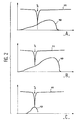
- Part A of the figure represents the curve 10 of the gain of the cavity laser as a function of wavelength and curve 11 represents the losses of this same cavity as a function wavelength.
- the laser can only work insofar as the losses are less than the gain.
- the value of the respective reflection coefficients of the outlet face 9 of the cavity and of the network 6 are such that this only happens for the length ⁇ which is the reflection wavelength of the network 6. This is due to the fact that the reflected light by the network is greater than the amount of light reflected by the output face 9.
- the value of the coefficient of reflection of the output face 9 is typically of 0.1% while the value of the reflection coefficient of network 6 is typically in the range of percent everything remaining less than or equal to 5%.
- the emission frequency of the laser at the interior of the range authorized by the middle is determined by the reflection wavelength of the network. As explained above, this results in a high operating stability.
- the curves in part A are representative of operation at 25 ° C.
- the same curves 10 and 11 have been shown in parts B and C in Figure 2 for temperature values of + 70 ° C and - 20 ° C respectively.
- the laser according to the invention can naturally be used for the same purposes as those described in the prior art cited and consisting in particular of pumping a power laser constituted by a fiber doped with erbium.
Landscapes
- Physics & Mathematics (AREA)
- Condensed Matter Physics & Semiconductors (AREA)
- General Physics & Mathematics (AREA)
- Electromagnetism (AREA)
- Optics & Photonics (AREA)
- Semiconductor Lasers (AREA)
- Laser Beam Processing (AREA)
- Laser Surgery Devices (AREA)
- Lasers (AREA)
Abstract
Description
- des moyens de couplage de la sortie laser à une fibre optique,
- la fibre optique ayant un réseau sur fibre renvoyant vers la cavité laser par l'intermédiaire des moyens de couplage une fraction de la lumière reçue du laser par la fibre.
- un laser à puits quantiques ayant une cavité laser formée par un milieu laser entre une face de réflexion et une face de sortie renvoyant vers la cavité une partie de l'énergie lumineuse, la cavité ayant une courbe de gain en fonction de la longueur d'onde présentant pour des longueurs d'onde croissantes une pente positive, un maximum pour une longueur d'onde λmax puis une pente négative,
- des moyens de couplage de la sortie laser à une fibre optique, la fibre optique ayant un réseau sur fibre définissant un coefficient d'un pic de réflexion pour une longueur d'onde λ et renvoyant vers la cavité laser au travers des moyens de couplage une fraction de la lumière reçue du laser par la fibre,
- dispositif caractérisé en ce que la valeur de la longueur d'onde λ définissant le pic de réflexion du réseau de Bragg de la fibre est inférieure d'au moins 10 nanomètres à la valeur de la longueur d'onde λmax.
- La figure 1 est un schéma représentant un mode de réalisation de l'invention.
- La figure 2 est un ensemble de trois paires de courbes chaque paire représentant le gain et les pertes de la cavité laser respectivement. La paire de courbes A représente le gain et les pertes de la cavité laser à 25°C, la paire de courbes B à 70°C, la paire de courbes C à -25°C.
Claims (6)
- Dispositif optique comprenant :un laser à puits quantiques ayant une cavité laser formée par un milieu laser entre une face de réflexion (8) et une face de sortie (9) renvoyant vers la cavité une partie de l'énergie lumineuse, la cavité ayant une courbe de gain en fonction de la longueur d'onde présentant pour des longueurs d'onde croissantes une pente positive, un maximum pour une longueur d'onde λmax puis une pente négative,des moyens de couplage (2,3,4) de la sortie laser à une fibre optique (5), la fibre optique ayant un réseau sur fibre (6) définissant un coefficient d'un pic de réflexion pour une longueur d'onde λ et renvoyant vers la cavité laser au travers des moyens de couplage (2,3,4) une fraction de la lumière reçue du laser par la fibre,dispositif caractérisé en ce que la valeur de la longueur d'onde λ définissant le pic de réflexion du réseau de Bragg de la fibre est inférieure d'au moins 10 nm à la valeur de la longueur d'onde λmax à température ambiante (25°C).
- Dispositif optique selon la revendication 1 caractérisé en ce que la valeur de la longueur d'onde λ définissant le pic de réflexion du réseau de Bragg de la fibre est inférieure de 15 plus ou moins 5 nm à la valeur de la longueur d'onde λmax.
- Dispositif optique selon la revendication 1 ou 2 caractérisé en ce que la valeur du coefficient de réflexion du réseau (6) est plus de 10 fois supérieure au coefficient de réflexion de la face (9) de sortie du laser.
- Dispositif optique selon la revendication 1, caractérisé en ce que la longueur d'onde λmax est une longueur d'onde qui a une valeur supérieure d'environ 13 nm à la valeur de la longueur d'onde λ pour laquelle le réseau (6) présente un pic de réflexion lorsque la température de fonctionnement a une valeur égale à 25°C.
- Dispositif optique selon la revendication 2, caractérisé en ce que la longueur d'onde λmax est une longueur d'onde qui a une valeur supérieure d'environ 13 nm à la valeur de la longueur d'onde λ pour laquelle le réseau (6) présente un pic de réflexion lorsque la température de fonctionnement a une valeur égale à 25°C.
- Dispositif optique selon la revendication 3, caractérisé en ce que la longueur d'onde λmax est une longueur d'onde qui a une valeur supérieure d'environ 13 nm à la valeur de la longueur d'onde λ pour laquelle le réseau (6) présente un pic de réflexion lorsque la température de fonctionnement a une valeur égale à 25°C.
Applications Claiming Priority (2)
| Application Number | Priority Date | Filing Date | Title |
|---|---|---|---|
| FR9905528A FR2793077B1 (fr) | 1999-04-30 | 1999-04-30 | Laser a gamme de temperature de fonctionnement etendue |
| FR9905528 | 1999-04-30 |
Publications (2)
| Publication Number | Publication Date |
|---|---|
| EP1049220A1 true EP1049220A1 (fr) | 2000-11-02 |
| EP1049220B1 EP1049220B1 (fr) | 2009-06-03 |
Family
ID=9545096
Family Applications (1)
| Application Number | Title | Priority Date | Filing Date |
|---|---|---|---|
| EP00401137A Expired - Lifetime EP1049220B1 (fr) | 1999-04-30 | 2000-04-25 | Laser à gamme de température de fonctionnement étendue |
Country Status (7)
| Country | Link |
|---|---|
| US (1) | US6952437B1 (fr) |
| EP (1) | EP1049220B1 (fr) |
| JP (1) | JP2000332352A (fr) |
| AT (1) | ATE433217T1 (fr) |
| CA (1) | CA2306318A1 (fr) |
| DE (1) | DE60042293D1 (fr) |
| FR (1) | FR2793077B1 (fr) |
Families Citing this family (5)
| Publication number | Priority date | Publication date | Assignee | Title |
|---|---|---|---|---|
| JP3729170B2 (ja) * | 2002-10-18 | 2005-12-21 | 住友電気工業株式会社 | 半導体レーザ |
| WO2005117302A1 (fr) * | 2004-05-25 | 2005-12-08 | Neowave Inc. | Dispositif a source lumineuse monomode presentant une cavite externe |
| US9184564B2 (en) * | 2013-06-07 | 2015-11-10 | Ngk Insulators, Ltd. | External resonator type light emitting system |
| WO2015079939A1 (fr) | 2013-11-27 | 2015-06-04 | 日本碍子株式会社 | Dispositif électroluminescent de type résonateur externe |
| US9331454B2 (en) | 2013-11-27 | 2016-05-03 | Ngk Insulators, Ltd. | External resonator type light emitting system |
Citations (4)
| Publication number | Priority date | Publication date | Assignee | Title |
|---|---|---|---|---|
| US5563732A (en) * | 1994-01-06 | 1996-10-08 | At&T Corp. | Laser pumping of erbium amplifier |
| EP0772267A1 (fr) * | 1995-10-31 | 1997-05-07 | Nec Corporation | Dispositif laser à diode |
| JPH09148660A (ja) * | 1995-11-24 | 1997-06-06 | Mitsubishi Electric Corp | 半導体レーザ装置および光増幅装置 |
| US5715263A (en) * | 1994-06-28 | 1998-02-03 | Sdl, Inc. | Fibre-grating-stabilized diode laser |
Family Cites Families (3)
| Publication number | Priority date | Publication date | Assignee | Title |
|---|---|---|---|---|
| FR2741482B1 (fr) * | 1995-11-21 | 1997-12-26 | Alcatel Optronics | Dispositif laser, notamment pour pompage optique, et son procede de fabrication |
| US6058128A (en) * | 1996-03-25 | 2000-05-02 | Sdl, Inc. | Apparatus for providing a stabilized laser source |
| JPH11214799A (ja) * | 1998-01-26 | 1999-08-06 | Furukawa Electric Co Ltd:The | 半導体レーザモジュール |
-
1999
- 1999-04-30 FR FR9905528A patent/FR2793077B1/fr not_active Expired - Fee Related
-
2000
- 2000-04-14 JP JP2000113011A patent/JP2000332352A/ja not_active Withdrawn
- 2000-04-17 US US09/550,596 patent/US6952437B1/en not_active Expired - Lifetime
- 2000-04-18 CA CA002306318A patent/CA2306318A1/fr not_active Abandoned
- 2000-04-25 EP EP00401137A patent/EP1049220B1/fr not_active Expired - Lifetime
- 2000-04-25 AT AT00401137T patent/ATE433217T1/de not_active IP Right Cessation
- 2000-04-25 DE DE60042293T patent/DE60042293D1/de not_active Expired - Lifetime
Patent Citations (4)
| Publication number | Priority date | Publication date | Assignee | Title |
|---|---|---|---|---|
| US5563732A (en) * | 1994-01-06 | 1996-10-08 | At&T Corp. | Laser pumping of erbium amplifier |
| US5715263A (en) * | 1994-06-28 | 1998-02-03 | Sdl, Inc. | Fibre-grating-stabilized diode laser |
| EP0772267A1 (fr) * | 1995-10-31 | 1997-05-07 | Nec Corporation | Dispositif laser à diode |
| JPH09148660A (ja) * | 1995-11-24 | 1997-06-06 | Mitsubishi Electric Corp | 半導体レーザ装置および光増幅装置 |
Non-Patent Citations (1)
| Title |
|---|
| PATENT ABSTRACTS OF JAPAN vol. 1997, no. 10 31 October 1997 (1997-10-31) * |
Also Published As
| Publication number | Publication date |
|---|---|
| US6952437B1 (en) | 2005-10-04 |
| FR2793077A1 (fr) | 2000-11-03 |
| CA2306318A1 (fr) | 2000-10-30 |
| ATE433217T1 (de) | 2009-06-15 |
| DE60042293D1 (de) | 2009-07-16 |
| JP2000332352A (ja) | 2000-11-30 |
| EP1049220B1 (fr) | 2009-06-03 |
| FR2793077B1 (fr) | 2001-07-27 |
Similar Documents
| Publication | Publication Date | Title |
|---|---|---|
| FR2731525A1 (fr) | Amplificateur optique a gain commandable et procede de commande d'un gain optique | |
| FR2774482A1 (fr) | Procede d'egalisation de gain, dispositif et systeme pour une utilisation dans la mise en oeuvre du procede | |
| FR2765752A1 (fr) | Amplificateur a fibre optique pour atteindre un gain eleve d'un petit signal | |
| FR2696286A1 (fr) | Laser à semiconducteur commandé par cavité externe. | |
| FR2740620A1 (fr) | Amplificateur optique, et ensemble le comportant | |
| EP0704945B1 (fr) | Amplificateur optique régulé à circulateur optique | |
| WO2019002763A1 (fr) | Source laser à semi-conducteur | |
| FR2803443A1 (fr) | Dispositif de generation d'impulsions laser a tres forte puissance crete, moyens de compression et d'etirement correspondants | |
| FR2737584A1 (fr) | Amplificateur de lumiere comportant un isolateur optique multietage | |
| EP0881790B1 (fr) | Système de transmission optique à compensation dynamique de la puissance transmise | |
| EP1049220B1 (fr) | Laser à gamme de température de fonctionnement étendue | |
| EP0508880B1 (fr) | Amplificateur optique à fibre optique dopée à l'erbium | |
| FR2752068A1 (fr) | Systeme d'amplification optique ayant plusieurs unites de derivation et procede d'amplification optique | |
| FR2790105A1 (fr) | Systeme, ligne et procede de transmission a fibre optique | |
| FR2765422A1 (fr) | Amplificateur a fibre optique muni d'un absorbeur | |
| FR2752067A1 (fr) | Amplificateur a fibre optique dopee a l'erbium, pour tracer et filtrer automatiquement une longueur d'onde de lumiere emise, et procede pour sa mise en oeuvre | |
| WO1997003488A1 (fr) | Source de lumiere a spectre large stabilise et gyroscope a fibre optique associe | |
| FR2801110A1 (fr) | Fibre optique concue pour realiser des filtres egalisateur de gain d'amplificateur a fibre dopee | |
| EP1306941A1 (fr) | Cavité optique résonante sur une plage continue de fréquence | |
| EP0452669B1 (fr) | Amplificateur optique à fibre dopée à l'erbium | |
| EP0977327A1 (fr) | Laser en espace libre avec sortie fibre autoalignée | |
| EP1065767A1 (fr) | Source laser avec filtrage intégré de l'émission spontanée amplifiée | |
| FR2819895A1 (fr) | Dispositif laser a couplage compensateur passif | |
| FR3084158A1 (fr) | Methode et dispositif de caracterisation de filtres optiques | |
| FR2826809A1 (fr) | Unite de source de lumiere a longueur d'onde variable |
Legal Events
| Date | Code | Title | Description |
|---|---|---|---|
| PUAI | Public reference made under article 153(3) epc to a published international application that has entered the european phase |
Free format text: ORIGINAL CODE: 0009012 |
|
| AK | Designated contracting states |
Kind code of ref document: A1 Designated state(s): AT BE CH CY DE DK ES FI FR GB GR IE IT LI LU MC NL PT SE |
|
| AX | Request for extension of the european patent |
Free format text: AL;LT;LV;MK;RO;SI |
|
| 17P | Request for examination filed |
Effective date: 20010414 |
|
| AKX | Designation fees paid |
Free format text: AT BE CH CY DE DK ES FI FR GB GR IE IT LI LU MC NL PT SE |
|
| RAP1 | Party data changed (applicant data changed or rights of an application transferred) |
Owner name: AVANEX CORPORATION |
|
| 17Q | First examination report despatched |
Effective date: 20070619 |
|
| GRAP | Despatch of communication of intention to grant a patent |
Free format text: ORIGINAL CODE: EPIDOSNIGR1 |
|
| RIN1 | Information on inventor provided before grant (corrected) |
Inventor name: GELLY, GERARD Inventor name: BETTIATI, MAURO |
|
| GRAS | Grant fee paid |
Free format text: ORIGINAL CODE: EPIDOSNIGR3 |
|
| GRAA | (expected) grant |
Free format text: ORIGINAL CODE: 0009210 |
|
| AK | Designated contracting states |
Kind code of ref document: B1 Designated state(s): AT BE CH CY DE DK ES FI FR GB GR IE IT LI LU MC NL PT SE |
|
| REG | Reference to a national code |
Ref country code: GB Ref legal event code: FG4D Free format text: NOT ENGLISH |
|
| REG | Reference to a national code |
Ref country code: CH Ref legal event code: EP |
|
| REG | Reference to a national code |
Ref country code: IE Ref legal event code: FG4D Free format text: LANGUAGE OF EP DOCUMENT: FRENCH |
|
| REF | Corresponds to: |
Ref document number: 60042293 Country of ref document: DE Date of ref document: 20090716 Kind code of ref document: P |
|
| PG25 | Lapsed in a contracting state [announced via postgrant information from national office to epo] |
Ref country code: AT Free format text: LAPSE BECAUSE OF FAILURE TO SUBMIT A TRANSLATION OF THE DESCRIPTION OR TO PAY THE FEE WITHIN THE PRESCRIBED TIME-LIMIT Effective date: 20090603 Ref country code: FI Free format text: LAPSE BECAUSE OF FAILURE TO SUBMIT A TRANSLATION OF THE DESCRIPTION OR TO PAY THE FEE WITHIN THE PRESCRIBED TIME-LIMIT Effective date: 20090603 |
|
| NLV1 | Nl: lapsed or annulled due to failure to fulfill the requirements of art. 29p and 29m of the patents act | ||
| PG25 | Lapsed in a contracting state [announced via postgrant information from national office to epo] |
Ref country code: NL Free format text: LAPSE BECAUSE OF FAILURE TO SUBMIT A TRANSLATION OF THE DESCRIPTION OR TO PAY THE FEE WITHIN THE PRESCRIBED TIME-LIMIT Effective date: 20090603 Ref country code: SE Free format text: LAPSE BECAUSE OF FAILURE TO SUBMIT A TRANSLATION OF THE DESCRIPTION OR TO PAY THE FEE WITHIN THE PRESCRIBED TIME-LIMIT Effective date: 20090903 |
|
| REG | Reference to a national code |
Ref country code: IE Ref legal event code: FD4D |
|
| PG25 | Lapsed in a contracting state [announced via postgrant information from national office to epo] |
Ref country code: IE Free format text: LAPSE BECAUSE OF FAILURE TO SUBMIT A TRANSLATION OF THE DESCRIPTION OR TO PAY THE FEE WITHIN THE PRESCRIBED TIME-LIMIT Effective date: 20090603 Ref country code: ES Free format text: LAPSE BECAUSE OF FAILURE TO SUBMIT A TRANSLATION OF THE DESCRIPTION OR TO PAY THE FEE WITHIN THE PRESCRIBED TIME-LIMIT Effective date: 20090914 |
|
| PG25 | Lapsed in a contracting state [announced via postgrant information from national office to epo] |
Ref country code: PT Free format text: LAPSE BECAUSE OF FAILURE TO SUBMIT A TRANSLATION OF THE DESCRIPTION OR TO PAY THE FEE WITHIN THE PRESCRIBED TIME-LIMIT Effective date: 20091003 |
|
| PLBE | No opposition filed within time limit |
Free format text: ORIGINAL CODE: 0009261 |
|
| STAA | Information on the status of an ep patent application or granted ep patent |
Free format text: STATUS: NO OPPOSITION FILED WITHIN TIME LIMIT |
|
| PG25 | Lapsed in a contracting state [announced via postgrant information from national office to epo] |
Ref country code: DK Free format text: LAPSE BECAUSE OF FAILURE TO SUBMIT A TRANSLATION OF THE DESCRIPTION OR TO PAY THE FEE WITHIN THE PRESCRIBED TIME-LIMIT Effective date: 20090603 |
|
| 26N | No opposition filed |
Effective date: 20100304 |
|
| PG25 | Lapsed in a contracting state [announced via postgrant information from national office to epo] |
Ref country code: GR Free format text: LAPSE BECAUSE OF FAILURE TO SUBMIT A TRANSLATION OF THE DESCRIPTION OR TO PAY THE FEE WITHIN THE PRESCRIBED TIME-LIMIT Effective date: 20090904 |
|
| BERE | Be: lapsed |
Owner name: AVANEX CORP. Effective date: 20100430 |
|
| PG25 | Lapsed in a contracting state [announced via postgrant information from national office to epo] |
Ref country code: MC Free format text: LAPSE BECAUSE OF NON-PAYMENT OF DUE FEES Effective date: 20100430 |
|
| REG | Reference to a national code |
Ref country code: CH Ref legal event code: PL |
|
| PG25 | Lapsed in a contracting state [announced via postgrant information from national office to epo] |
Ref country code: CH Free format text: LAPSE BECAUSE OF NON-PAYMENT OF DUE FEES Effective date: 20100430 Ref country code: LI Free format text: LAPSE BECAUSE OF NON-PAYMENT OF DUE FEES Effective date: 20100430 |
|
| PG25 | Lapsed in a contracting state [announced via postgrant information from national office to epo] |
Ref country code: BE Free format text: LAPSE BECAUSE OF NON-PAYMENT OF DUE FEES Effective date: 20100430 Ref country code: IT Free format text: LAPSE BECAUSE OF FAILURE TO SUBMIT A TRANSLATION OF THE DESCRIPTION OR TO PAY THE FEE WITHIN THE PRESCRIBED TIME-LIMIT Effective date: 20090603 |
|
| PG25 | Lapsed in a contracting state [announced via postgrant information from national office to epo] |
Ref country code: CY Free format text: LAPSE BECAUSE OF FAILURE TO SUBMIT A TRANSLATION OF THE DESCRIPTION OR TO PAY THE FEE WITHIN THE PRESCRIBED TIME-LIMIT Effective date: 20090603 |
|
| PG25 | Lapsed in a contracting state [announced via postgrant information from national office to epo] |
Ref country code: LU Free format text: LAPSE BECAUSE OF NON-PAYMENT OF DUE FEES Effective date: 20100425 |
|
| REG | Reference to a national code |
Ref country code: GB Ref legal event code: 732E Free format text: REGISTERED BETWEEN 20140227 AND 20140305 |
|
| REG | Reference to a national code |
Ref country code: DE Ref legal event code: R081 Ref document number: 60042293 Country of ref document: DE Owner name: II-VI LASER ENTERPRISE GMBH, CH Free format text: FORMER OWNER: AVANEX CORP., FREMONT, CALIF., US Effective date: 20140718 |
|
| REG | Reference to a national code |
Ref country code: FR Ref legal event code: PLFP Year of fee payment: 16 |
|
| REG | Reference to a national code |
Ref country code: FR Ref legal event code: TP Owner name: II-VI LASER ENTERPRISE GMBH, CH Effective date: 20160316 Ref country code: FR Ref legal event code: CA Effective date: 20160316 Ref country code: FR Ref legal event code: CD Owner name: II-VI LASER ENTERPRISE GMBH, CH Effective date: 20160316 |
|
| REG | Reference to a national code |
Ref country code: FR Ref legal event code: PLFP Year of fee payment: 17 |
|
| REG | Reference to a national code |
Ref country code: FR Ref legal event code: PLFP Year of fee payment: 18 |
|
| REG | Reference to a national code |
Ref country code: FR Ref legal event code: PLFP Year of fee payment: 19 |
|
| PGFP | Annual fee paid to national office [announced via postgrant information from national office to epo] |
Ref country code: DE Payment date: 20190429 Year of fee payment: 20 |
|
| PGFP | Annual fee paid to national office [announced via postgrant information from national office to epo] |
Ref country code: FR Payment date: 20190425 Year of fee payment: 20 |
|
| PGFP | Annual fee paid to national office [announced via postgrant information from national office to epo] |
Ref country code: GB Payment date: 20190429 Year of fee payment: 20 |
|
| REG | Reference to a national code |
Ref country code: DE Ref legal event code: R071 Ref document number: 60042293 Country of ref document: DE |
|
| REG | Reference to a national code |
Ref country code: GB Ref legal event code: PE20 Expiry date: 20200424 |
|
| PG25 | Lapsed in a contracting state [announced via postgrant information from national office to epo] |
Ref country code: GB Free format text: LAPSE BECAUSE OF EXPIRATION OF PROTECTION Effective date: 20200424 |