EP1049216A2 - Panel mounted connector - Google Patents
Panel mounted connector Download PDFInfo
- Publication number
- EP1049216A2 EP1049216A2 EP00108904A EP00108904A EP1049216A2 EP 1049216 A2 EP1049216 A2 EP 1049216A2 EP 00108904 A EP00108904 A EP 00108904A EP 00108904 A EP00108904 A EP 00108904A EP 1049216 A2 EP1049216 A2 EP 1049216A2
- Authority
- EP
- European Patent Office
- Prior art keywords
- connector
- panel
- housing
- mating
- arm
- Prior art date
- Legal status (The legal status is an assumption and is not a legal conclusion. Google has not performed a legal analysis and makes no representation as to the accuracy of the status listed.)
- Granted
Links
Images


Classifications
-
- H—ELECTRICITY
- H01—ELECTRIC ELEMENTS
- H01R—ELECTRICALLY-CONDUCTIVE CONNECTIONS; STRUCTURAL ASSOCIATIONS OF A PLURALITY OF MUTUALLY-INSULATED ELECTRICAL CONNECTING ELEMENTS; COUPLING DEVICES; CURRENT COLLECTORS
- H01R13/00—Details of coupling devices of the kinds covered by groups H01R12/70 or H01R24/00 - H01R33/00
- H01R13/73—Means for mounting coupling parts to apparatus or structures, e.g. to a wall
- H01R13/74—Means for mounting coupling parts in openings of a panel
- H01R13/741—Means for mounting coupling parts in openings of a panel using snap fastening means
- H01R13/743—Means for mounting coupling parts in openings of a panel using snap fastening means integral with the housing
Definitions
- This invention generally relates to the art of connector assemblies, such as electric connectors, fiber optic connectors and the like. More particularly, the invention relates to a system for restricting movement of a connector relative to a panel in a given mating direction and releasing the restrictions once a given mating force on the connector is exceeded.
- a connector is mounted through an aperture in a chassis such as a panel or the like. It often is desirable to mount the connector so that it has some degree of limited movement or "float" relative to the chassis or panel. For instance, in an automotive application, the chassis or panel and its mounted connector must be assembled in relation to another frame component or a printed circuit board, backplane or the like. By providing some degree of floating movement for the connector, accommodation is made for manufacturing tolerances when the entire system is assembled.
- the present invention is directed to solving this problem by providing a unique system wherein a panel-mounted connector is restricted against movement relative to the panel in a mating direction, and the restriction is released in response to a force greater than a given mating force being exceeded.
- An object, therefore, of the invention is to provide a new and improved connector for mounting through an aperture in a panel, the connector being mateable with a complementary connecting device with a given mating force in a given mating direction.
- the connector includes a housing mountable in the aperture in the panel.
- the housing includes engagement means for restricting movement of the connector relative to the panel in the mating direction.
- a release means is operatively associated with the engagement means to release the engagement means and allow movement of the connector relative to the panel in the mating direction in response to a force greater than the given mating force.
- the engagement means is provided by an engaging member movable relative to the housing.
- the release means is provided by a frangible component joining the engaging member to the housing.
- the frangible component is breakable in response to a force greater than the given mating force.
- the housing is molded of plastic material and the frangible component is provided by an integrally molded, frangible web interconnected between the engaging member and the housing.
- the engaging member is formed by a cantilevered flexible arm having an abutment portion at a free distal end of the arm.
- the frangible web is interconnected between the free end of the arm and the housing.
- a plurality of the cantilevered flexible arms are provided generally at opposite sides of a mating portion of the housing.
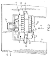
- the connector includes a one-piece unitarily molded plastic housing, generally designated 16.
- the housing includes a mating portion 18 defining a mating end 20, along with a terminating portion 22 defining a terminating end 24.
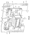
- Mating portion 18 of connector 10 is insertable into a complementary mating connecting device or receptacle in a mating direction as indicated by arrow "A" (Fig. 3).
- the complementary connecting device will include terminals for insertion into appropriate terminal-receiving passages 26 (Fig. 3) for engagement with terminals within connector housing 16, the terminals not being visible in the drawings.
- Terminating portion 22 of connector 10 includes a plurality of passages 28 (Figs. 1 and 2) through which electrical wires are inserted.
- the conductors of the wires are terminated to the terminals in the housing.
- the wires are terminated to the terminals before inserting the terminals into passages 28 in the housing.
- Unitarily molded housing 16 of connector 10 includes a main flange 30 and a plurality of stop flanges 32 which are spaced from the main flange to sandwich panel 14 therebetween as is clearly seen in Figures 2 and 3.
- the connector is inserted into cutout 12 in panel 14 in the direction of arrows "B".
- Stop flanges 32 project radially outwardly from flexible arms 34 which are engageable with the three sides of cutout 12 to allow for a given amount of relative movement or "floating" action between the connector and the panel in directions generally parallel to the panel.
- engagement means generally designated 36
- engagement means for restricting movement of connector 10 relative to panel 14 in mating direction "A”.
- a pair of flexible cantilevered engagement arms 38 are molded integrally with the housing, and each arm includes a proximal end 38a and a distal end 38b. As will be seen hereinafter, when the arms are released, the arms can flex or pivot about proximal ends 38a.
- Each arm includes an abutment boss 40 near distal end 38b of the arm for engaging an insertion side 42 of panel 14.
- frangible webs 44 comprise plastic webs integrally molded between main flange 30 of housing 16 and distal ends 38b of engagement arms 38.
- the webs can be sized to break in response to any given or predetermined force. Obviously, the larger the web the greater amount of force will be required to break the web.
- the mating force between connector 10 and the complementary mating connecting device comprises a composite force equal to the forces required for mating all of the terminals within connector 10 to the terminals of the mating connecting device.
- This mating force can be easily calculated and would provide a "given mating force" of the connector assembly.
- some terminal manufacturers provide specifications on the mating forces required for specific mating terminals. Therefore, it can be understood that frangible webs 44 can be made of a size to break-away in response to a force somewhat greater than the given or calculated mating force.
- frangible webs 44 to break only when the given mating force of the connector assembly is exceeded, connector 10 can be fully mated with the complementary connecting device while engagement arms and frangible webs 44 restrict movement of the connector relative to the panel in mating direction "A". However, when the given mating force is exceeded, frangible webs 44 will break and allow movement of connector 10 relative to panel 14 in the mating direction.
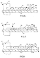
- Figures 4-7 show the break-away action of one of the engagement arms 38 of connector 10 relative to panel 14. More particularly, Figures 4 and 6 show the engagement arm with abutment boss 40 engaging the mating side 42 of panel 14. As seen in Figure 6, frangible web 44 still joins distal end 38b of the engagement arm with main flange 30 of connector housing 16. Figures 5 and 7 show that the connector has been moved in mating direction "A" (Fig. 7) to an extent that frangible web 44 has been broken, as at 50. This condition would occur when the given mating force between connector 10 and the complementary mating connecting device has been exceeded and the break-away resistance of the frangible web also has been exceeded.
- Figure 8 shows that engagement arm 38, being fabricated of plastic material, actually acts as a spring member to bias the connector to a sort of "neutral" position notwithstanding the fact that frangible web 44 has been broken. Therefore, after the given mating force has been exceeded to the extent of breaking frangible web 44, the resiliency in flexible cantilevered engagement arm 38 allows connector 10 to float relative to panel 14 in the direction of double-headed arrow "C" (Fig. 8).
Landscapes
- Details Of Connecting Devices For Male And Female Coupling (AREA)
Abstract
Description
Claims (14)
- A connector (10) for mounting in an aperture (12) in a panel (14), the connector being mateable with a complementary connecting device with a given mating force in a given mating direction (A), comprising:a housing (16) mountable in the aperture (12) in the panel (14) and including engagement means (36) for restricting movement of the connector (10) relative to the panel (14) in said mating direction (A); andrelease means (44) operatively associated with said engagement means (36) to release the engagement means and allow movement of the connector (10) relative to the panel (14) in said mating direction (A) in response to a force greater than said given mating force.
- The connector of claim 1 wherein said engagement means (36,40) is located for abutting she panel (14) on an insertion side (42) thereof.
- The connector of claim 1 wherein said engagement means (36) comprises a spring member (38).
- The connector of claim 1 wherein said engagement means (36) comprises an engaging member (38) movable relative to the housing, and said release means comprises a frangible component (44) joining the engaging member (38) to the housing (16), the frangible component (44) being breakable in response to a force greater than said given mating force.
- The connector of claim 4 wherein said housing (16) is molded of plastic material and said frangible component comprises an integrally molded, frangible web (44) interconnected between the engaging member (38) and the housing.
- The connector of claim 1 wherein said engaging means comprises an engagement arm (38) having a panel abutment portion (40).
- The connector of claim 6 wherein said engagement arm is a cantilevered arm (38) with said panel abutment portion (40) at a free distal end (38b) of the arm.
- The connector of claim 7 wherein said release means (44) is operatively associated with the free end (38b) of the cantilevered arm (38).
- The connector of claim 8, including a plurality of said cantilevered arms (38) at opposite sides of the housing (16).
- The connector of claim 9 wherein said housing (16) includes a mating portion (18), and said arms (38) are located generally at opposite sides of the mating portion.
- A connector (10) for mounting in an aperture (12) in a panel (14), the connector being mateable with a complementary connecting device with a given mating force in a given mating direction (A), comprising:a housing (16) mountable in the aperture (12) in the panel (14) and including at least one cantilevered flexible engagement arm (38) having a panel abutment portion (40) at a free distal end (38b) of the arm for restricting movement of the connector (10) relative to the panel (14) in said mating direction (A); anda frangible component (44) joining the engagement arm (38) to the housing (16), the frangible component (44) being breakable in response to a force greater than said given mating force.
- The connector of claim 11 wherein said housing (16) is molded of plastic material and said frangible component comprises an integrally molded, frangible web (44) interconnected between the engaging arm (38) and the housing (16).
- The connector of claim 11, including a plurality of said cantilevered flexible arms (38) at opposite sides of the housing (16).
- The connector of claim 13 wherein said housing (16) includes a mating portion (18), and said arms (38) are located generally at opposite sides of the mating portion.
Applications Claiming Priority (2)
| Application Number | Priority Date | Filing Date | Title |
|---|---|---|---|
| US09/301,654 US6174185B1 (en) | 1999-04-28 | 1999-04-28 | Panel mounted connector |
| US301654 | 1999-04-28 |
Publications (3)
| Publication Number | Publication Date |
|---|---|
| EP1049216A2 true EP1049216A2 (en) | 2000-11-02 |
| EP1049216A3 EP1049216A3 (en) | 2003-12-17 |
| EP1049216B1 EP1049216B1 (en) | 2006-06-21 |
Family
ID=23164290
Family Applications (1)
| Application Number | Title | Priority Date | Filing Date |
|---|---|---|---|
| EP00108904A Expired - Lifetime EP1049216B1 (en) | 1999-04-28 | 2000-04-27 | Panel mounted connector |
Country Status (4)
| Country | Link |
|---|---|
| US (1) | US6174185B1 (en) |
| EP (1) | EP1049216B1 (en) |
| JP (1) | JP3355406B2 (en) |
| DE (1) | DE60028859T2 (en) |
Cited By (2)
| Publication number | Priority date | Publication date | Assignee | Title |
|---|---|---|---|---|
| CN101071919B (en) * | 2006-04-27 | 2011-03-02 | 泰科电子公司 | Slide-to-latch panel mount connector |
| CN112054334A (en) * | 2019-06-07 | 2020-12-08 | 泰连公司 | Charging systems for mobile devices |
Families Citing this family (14)
| Publication number | Priority date | Publication date | Assignee | Title |
|---|---|---|---|---|
| JP2002093502A (en) * | 2000-09-14 | 2002-03-29 | Fujitsu Ten Ltd | Floating connector |
| US6506081B2 (en) * | 2001-05-31 | 2003-01-14 | Tyco Electronics Corporation | Floatable connector assembly with a staggered overlapping contact pattern |
| JP2002368449A (en) * | 2001-06-04 | 2002-12-20 | Matsushita Electric Ind Co Ltd | Magnetic recording / reproducing device |
| EP2063499A3 (en) * | 2002-09-19 | 2009-11-11 | Sumitomo Wiring Systems, Ltd. | A connector assembly, connector, connector assembling construction and method of assembling them |
| JP4949936B2 (en) | 2007-06-08 | 2012-06-13 | 矢崎総業株式会社 | connector |
| US7540769B1 (en) * | 2007-11-19 | 2009-06-02 | Cheng Uei Precision Industry Co., Ltd. | Receptacle connector |
| JP5508806B2 (en) * | 2009-10-08 | 2014-06-04 | 矢崎エナジーシステム株式会社 | Panel mount type connector |
| DE102010002765A1 (en) | 2010-03-11 | 2011-09-15 | Robert Bosch Gmbh | Housing base of a multi-part housing and method for mounting a housing |
| JP5790245B2 (en) * | 2011-07-26 | 2015-10-07 | 第一精工株式会社 | Coaxial electrical connector and coaxial electrical connector assembly |
| WO2017173273A1 (en) * | 2016-04-01 | 2017-10-05 | Lutron Electronics Co., Inc. | Electrical receptacle assembly with outward-biasing faceplate |
| EP3604035B1 (en) * | 2018-07-30 | 2023-06-21 | Valeo Iluminacion | Electronic connection assembly, automotive lighting device and method for manufacturing an automotive lighting device |
| US12413028B2 (en) * | 2021-10-08 | 2025-09-09 | Te Connectivity Solutions Gmbh | Panel mount electrical connector |
| US20250047027A1 (en) * | 2023-07-31 | 2025-02-06 | Te Connectivity Solutions Gmbh | Electrical connector assembly having floating mating interface |
| US20250047037A1 (en) * | 2023-07-31 | 2025-02-06 | Te Connectivity Solutions Gmbh | Electrical connector assembly having floating mating interface |
Family Cites Families (9)
| Publication number | Priority date | Publication date | Assignee | Title |
|---|---|---|---|---|
| JP2568142B2 (en) * | 1991-12-30 | 1996-12-25 | モレックス インコーポレーテッド | Floating structure electrical connector and manufacturing method thereof |
| US5199900A (en) * | 1992-02-21 | 1993-04-06 | Amp Incorporated | Panel mount electrical connector |
| US5197896A (en) * | 1992-02-28 | 1993-03-30 | Amp Incorporated | Float mounting an electrical connector |
| GB9219328D0 (en) * | 1992-09-11 | 1992-10-28 | Amp Gmbh | Automotive door-to-body electrical |
| JP3140336B2 (en) * | 1995-08-01 | 2001-03-05 | 矢崎総業株式会社 | Movable connector mounting structure |
| JP3200546B2 (en) * | 1995-09-04 | 2001-08-20 | 矢崎総業株式会社 | Movable connector |
| US6159030A (en) * | 1997-06-16 | 2000-12-12 | Lear Automotive Dearborn, Inc. | Self-aligning connecting system |
| EP1012923B1 (en) * | 1997-06-16 | 2002-11-27 | The Whitaker Corporation | Floating connector assembly |
| US6024590A (en) * | 1997-09-05 | 2000-02-15 | Molex Incorporated | Self-aligning connector system for electrical connectors |
-
1999
- 1999-04-28 US US09/301,654 patent/US6174185B1/en not_active Expired - Fee Related
-
2000
- 2000-04-26 JP JP2000125313A patent/JP3355406B2/en not_active Expired - Fee Related
- 2000-04-27 EP EP00108904A patent/EP1049216B1/en not_active Expired - Lifetime
- 2000-04-27 DE DE60028859T patent/DE60028859T2/en not_active Expired - Fee Related
Cited By (3)
| Publication number | Priority date | Publication date | Assignee | Title |
|---|---|---|---|---|
| CN101071919B (en) * | 2006-04-27 | 2011-03-02 | 泰科电子公司 | Slide-to-latch panel mount connector |
| CN112054334A (en) * | 2019-06-07 | 2020-12-08 | 泰连公司 | Charging systems for mobile devices |
| CN112054334B (en) * | 2019-06-07 | 2024-06-04 | 泰连公司 | Charging system for mobile device |
Also Published As
| Publication number | Publication date |
|---|---|
| EP1049216B1 (en) | 2006-06-21 |
| DE60028859D1 (en) | 2006-08-03 |
| EP1049216A3 (en) | 2003-12-17 |
| JP3355406B2 (en) | 2002-12-09 |
| DE60028859T2 (en) | 2007-01-18 |
| JP2000348830A (en) | 2000-12-15 |
| US6174185B1 (en) | 2001-01-16 |
Similar Documents
| Publication | Publication Date | Title |
|---|---|---|
| US6174185B1 (en) | Panel mounted connector | |
| EP0635909B1 (en) | Printed circuit board electrical connector with mounting latch clip | |
| EP1143570B1 (en) | Floating panel mounted connector assembly | |
| US4657331A (en) | Strain relief for electrical connector assemblies | |
| CA1052453A (en) | Clip for printed circuit board edge connector | |
| EP0706237B1 (en) | Electrical connector with terminal position assurance device and guide means for a mating connector | |
| US5395251A (en) | Board retainer system for active electrical connector assembly | |
| EP0805523A2 (en) | Electrical connector latching system | |
| EP0717470A2 (en) | Floating panel mount system for electrical connectors | |
| US6305961B1 (en) | EMI gasket for connector assemblies | |
| EP1045486B1 (en) | Panel mounted connector assembly | |
| CA2508357C (en) | Flexible cable electrical connector | |
| EP0901197B1 (en) | Self-aligning connector system for electrical connectors | |
| JP2009530770A (en) | Receptacle connector assembly | |
| EP0948102B1 (en) | Card edge connector | |
| JP3463245B2 (en) | Electrical connector latch system | |
| EP0901189B1 (en) | Mounting system for an electrical connector assembly | |
| JP3099108B2 (en) | Electrical connector for flat flexible cable | |
| EP2162958A1 (en) | Low profile shorting bar for electrical connector | |
| EP0901199B1 (en) | Holding assembly for mounting electrical connectors | |
| EP1046200B1 (en) | Electric connector | |
| CN115189180B (en) | Electrical connector components |
Legal Events
| Date | Code | Title | Description |
|---|---|---|---|
| PUAI | Public reference made under article 153(3) epc to a published international application that has entered the european phase |
Free format text: ORIGINAL CODE: 0009012 |
|
| AK | Designated contracting states |
Kind code of ref document: A2 Designated state(s): AT BE CH CY DE DK ES FI FR GB GR IE IT LI LU MC NL PT SE |
|
| AX | Request for extension of the european patent |
Free format text: AL;LT;LV;MK;RO;SI |
|
| PUAL | Search report despatched |
Free format text: ORIGINAL CODE: 0009013 |
|
| AK | Designated contracting states |
Kind code of ref document: A3 Designated state(s): AT BE CH CY DE DK ES FI FR GB GR IE IT LI LU MC NL PT SE |
|
| AX | Request for extension of the european patent |
Extension state: AL LT LV MK RO SI |
|
| RIC1 | Information provided on ipc code assigned before grant |
Ipc: 7H 01R 13/631 B Ipc: 7H 01R 13/74 A |
|
| 17P | Request for examination filed |
Effective date: 20040529 |
|
| 17Q | First examination report despatched |
Effective date: 20040624 |
|
| AKX | Designation fees paid |
Designated state(s): DE FR GB IT |
|
| GRAP | Despatch of communication of intention to grant a patent |
Free format text: ORIGINAL CODE: EPIDOSNIGR1 |
|
| GRAS | Grant fee paid |
Free format text: ORIGINAL CODE: EPIDOSNIGR3 |
|
| GRAA | (expected) grant |
Free format text: ORIGINAL CODE: 0009210 |
|
| AK | Designated contracting states |
Kind code of ref document: B1 Designated state(s): DE FR GB IT |
|
| PG25 | Lapsed in a contracting state [announced via postgrant information from national office to epo] |
Ref country code: IT Free format text: LAPSE BECAUSE OF FAILURE TO SUBMIT A TRANSLATION OF THE DESCRIPTION OR TO PAY THE FEE WITHIN THE PRESCRIBED TIME-LIMIT;WARNING: LAPSES OF ITALIAN PATENTS WITH EFFECTIVE DATE BEFORE 2007 MAY HAVE OCCURRED AT ANY TIME BEFORE 2007. THE CORRECT EFFECTIVE DATE MAY BE DIFFERENT FROM THE ONE RECORDED. Effective date: 20060621 |
|
| REG | Reference to a national code |
Ref country code: GB Ref legal event code: FG4D |
|
| REF | Corresponds to: |
Ref document number: 60028859 Country of ref document: DE Date of ref document: 20060803 Kind code of ref document: P |
|
| ET | Fr: translation filed | ||
| PLBE | No opposition filed within time limit |
Free format text: ORIGINAL CODE: 0009261 |
|
| STAA | Information on the status of an ep patent application or granted ep patent |
Free format text: STATUS: NO OPPOSITION FILED WITHIN TIME LIMIT |
|
| 26N | No opposition filed |
Effective date: 20070322 |
|
| PGFP | Annual fee paid to national office [announced via postgrant information from national office to epo] |
Ref country code: IT Payment date: 20080424 Year of fee payment: 9 |
|
| PGFP | Annual fee paid to national office [announced via postgrant information from national office to epo] |
Ref country code: GB Payment date: 20080429 Year of fee payment: 9 |
|
| PGFP | Annual fee paid to national office [announced via postgrant information from national office to epo] |
Ref country code: FR Payment date: 20090417 Year of fee payment: 10 Ref country code: DE Payment date: 20090429 Year of fee payment: 10 |
|
| GBPC | Gb: european patent ceased through non-payment of renewal fee |
Effective date: 20090427 |
|
| PG25 | Lapsed in a contracting state [announced via postgrant information from national office to epo] |
Ref country code: GB Free format text: LAPSE BECAUSE OF NON-PAYMENT OF DUE FEES Effective date: 20090427 |
|
| REG | Reference to a national code |
Ref country code: FR Ref legal event code: ST Effective date: 20101230 |
|
| PG25 | Lapsed in a contracting state [announced via postgrant information from national office to epo] |
Ref country code: DE Free format text: LAPSE BECAUSE OF NON-PAYMENT OF DUE FEES Effective date: 20101103 |
|
| PG25 | Lapsed in a contracting state [announced via postgrant information from national office to epo] |
Ref country code: IT Free format text: LAPSE BECAUSE OF NON-PAYMENT OF DUE FEES Effective date: 20090427 |
|
| PG25 | Lapsed in a contracting state [announced via postgrant information from national office to epo] |
Ref country code: FR Free format text: LAPSE BECAUSE OF NON-PAYMENT OF DUE FEES Effective date: 20100430 |