EP1049211A2 - Multi-piece connector - Google Patents
Multi-piece connector Download PDFInfo
- Publication number
- EP1049211A2 EP1049211A2 EP00303562A EP00303562A EP1049211A2 EP 1049211 A2 EP1049211 A2 EP 1049211A2 EP 00303562 A EP00303562 A EP 00303562A EP 00303562 A EP00303562 A EP 00303562A EP 1049211 A2 EP1049211 A2 EP 1049211A2
- Authority
- EP
- European Patent Office
- Prior art keywords
- sub
- cover
- housing
- frame
- connectors
- Prior art date
- Legal status (The legal status is an assumption and is not a legal conclusion. Google has not performed a legal analysis and makes no representation as to the accuracy of the status listed.)
- Granted
Links
Images




Classifications
-
- H—ELECTRICITY
- H01—ELECTRIC ELEMENTS
- H01R—ELECTRICALLY-CONDUCTIVE CONNECTIONS; STRUCTURAL ASSOCIATIONS OF A PLURALITY OF MUTUALLY-INSULATED ELECTRICAL CONNECTING ELEMENTS; COUPLING DEVICES; CURRENT COLLECTORS
- H01R13/00—Details of coupling devices of the kinds covered by groups H01R12/70 or H01R24/00 - H01R33/00
- H01R13/73—Means for mounting coupling parts to apparatus or structures, e.g. to a wall
- H01R13/74—Means for mounting coupling parts in openings of a panel
- H01R13/741—Means for mounting coupling parts in openings of a panel using snap fastening means
- H01R13/743—Means for mounting coupling parts in openings of a panel using snap fastening means integral with the housing
-
- H—ELECTRICITY
- H01—ELECTRIC ELEMENTS
- H01R—ELECTRICALLY-CONDUCTIVE CONNECTIONS; STRUCTURAL ASSOCIATIONS OF A PLURALITY OF MUTUALLY-INSULATED ELECTRICAL CONNECTING ELEMENTS; COUPLING DEVICES; CURRENT COLLECTORS
- H01R13/00—Details of coupling devices of the kinds covered by groups H01R12/70 or H01R24/00 - H01R33/00
- H01R13/46—Bases; Cases
- H01R13/502—Bases; Cases composed of different pieces
- H01R13/506—Bases; Cases composed of different pieces assembled by snap action of the parts
-
- H—ELECTRICITY
- H01—ELECTRIC ELEMENTS
- H01R—ELECTRICALLY-CONDUCTIVE CONNECTIONS; STRUCTURAL ASSOCIATIONS OF A PLURALITY OF MUTUALLY-INSULATED ELECTRICAL CONNECTING ELEMENTS; COUPLING DEVICES; CURRENT COLLECTORS
- H01R13/00—Details of coupling devices of the kinds covered by groups H01R12/70 or H01R24/00 - H01R33/00
- H01R13/46—Bases; Cases
- H01R13/516—Means for holding or embracing insulating body, e.g. casing, hoods
- H01R13/518—Means for holding or embracing insulating body, e.g. casing, hoods for holding or embracing several coupling parts, e.g. frames
-
- Y—GENERAL TAGGING OF NEW TECHNOLOGICAL DEVELOPMENTS; GENERAL TAGGING OF CROSS-SECTIONAL TECHNOLOGIES SPANNING OVER SEVERAL SECTIONS OF THE IPC; TECHNICAL SUBJECTS COVERED BY FORMER USPC CROSS-REFERENCE ART COLLECTIONS [XRACs] AND DIGESTS
- Y10—TECHNICAL SUBJECTS COVERED BY FORMER USPC
- Y10S—TECHNICAL SUBJECTS COVERED BY FORMER USPC CROSS-REFERENCE ART COLLECTIONS [XRACs] AND DIGESTS
- Y10S439/00—Electrical connectors
- Y10S439/901—Connector hood or shell
- Y10S439/902—Angularly disposed contact and conductor
Definitions
- the present invention relates to a split electrical connector provided with a cover.
- a type of split electrical connector provided with a cover is described in JP-8-78097.
- This split connector has a configuration whereby a plurality of housing chambers are provided within a frame.
- a sub-connector housing is inserted from a posterior face into each housing chamber and is retained therein, and a cover is provided over a posterior face of each sub-connector housing, this cover being locked to a posterior edge of the frame.
- Electric wires which extend from the posterior face of each sub-connector housing are gathered together and housed within the cover, as a consequence they can be directed in a prescribed direction.
- the cover is fixed to the frame.
- the present invention has taken the above problem into consideration, and aims to present a split connector provided with a cover in which transportation and attachment are simplified.
- an electrical split connector comprising a frame adapted to be fixed in a panel, and defining a plurality of chambers, a plurality of sub-connectors having wires protruding therefrom and for insertion one each into said chambers, and a cover adapted to enclose and guide wires of said sub-connectors in a predetermined direction, characterised in that said sub-connectors and cover are provided with co-operating latch members, thereby to form a sub-assembly for subsequent insertion into said frame.
- said latch members comprise protrusions of said sub-connectors and cooperating openings of said cover.
- the openings may be provided on resilient projections of the cover, and the projections preferably extend in the fitting direction of the cover.
- the projections may laterally engage guide surfaces of one or more of said sub-connectors.
- the invention also comprises a method of inserting a plurality of sub-connectors into panel and comprising the steps of:
- a split connector of the present embodiment has two housing chambers 15 and 16 provided within a frame 10, these housing chambers 15 and 16 respectively housing two female sub-connector housings 20 and 30 (hereafter referred to as sub-housings).
- a cover 60 covers posterior faces of the sub-housings 20 and 30, and male connector housings (not shown) fit individually with anterior faces of each of the sub-housings 20 and 30.
- Figure 1 is an exploded view of the components.
- the frame 10 is cylindrical and is stepped so that an anterior face (at the top in Figure 1) is larger.
- the frame 10 is inserted from an anterior direction into an attachment hole 71 of a panel (see Figure 7) attached to a car body or the like.
- a stopping groove 11 formed on an outer circumference of an anterior edge of the frame 10 fits with a hole edge of the attachment hole 71, thereby attaching the frame 10.
- a partitioning wall 12 is formed at a posterior portion within the frame 10, this partitioning wall 12 dividing the frame 10 into left and right housing chambers. These form the first housing chamber 15 and the second housing chamber 16 respectively.
- the first sub-housing 20 and the second sub-housing 30 are respectively housed within these left and right housing chambers 15 and 16.
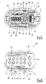
- the first sub-housing 20 has an approximately rectangular cross-sectional shape, the corners thereof being rounded.
- a plurality of cavities 22 (twelve are shown) formed in an aligned manner within a terminal housing member 21 form two rows, an upper and a lower row.
- a hood member 23 is formed on an outer circumference of an anterior face of the terminal housing member 21. Female terminal fittings (not shown) are inserted from a posterior direction into the cavities 22 and are housed therein.
- the second sub-housing 30 is smaller than the first sub-housing 20 described above. As shown in Figure 4, three cavities 32 are aligned vertically within a terminal housing member 31 thereof. A hood member 33 is formed on an outer circumference of an anterior face of this terminal housing member 31. Male terminal fittings are inserted into the cavities 32 from a posterior direction, and are housed therein.
- a stopping mechanism 40 is provided on a base face of a posterior end of the sub-housing 20 at a central portion thereof in a width-wise direction.
- the stopping mechanism 40 comprises a pair of left and right guiding rails 41 which are cross-sectionally hook shaped, mutually face one another, and are separated by a prescribed distance.
- a protrusion 42 is formed on a posterior end of each guiding rail 41.
- a stopping arm 45 is formed between the two guiding rails 41. This stopping arm 45 extends from its posterior end and protrudes in an anterior direction.
- a protruding member 46 is formed on a side face (the right face in Figure 1) of the stopping arm 45 at a location close to the tip thereof. An anterior face of this protruding member 46 forms a tapered face 47 which is used for guiding it.
- a pair of stopping plates 50 protrude upwards from a base face of a posterior end of the first housing chamber 15. As shown in Figure 5, these stopping plates 50 are cross-sectionally hook shaped and are positioned back to back. The stopping plates 50 are capable of being inserted into the interior of the guiding rails 41.
- a stopping member 51 is formed on an inner face of one of the stopping plates 50 (the stopping plate 50 on the right in Figure 1) at a location close to an anterior end thereof. This stopping member 51 is capable of engaging with the protruding member 46 of the stopping arm 45.
- a posterior face of the stopping member 51 forms a tapered face 52 which is used for guiding it.
- An auxiliary stopping member 53 is formed symmetrically on an inner face of the other stopping plate 50 at a location close to a posterior end thereof.
- a stopping mechanism 40 is provided on a posterior end of the second sub-housing 30 (on the left in Figure 1), this being identical with the stopping mechanism 40 of the first sub-housing 20.
- a pair of stopping plates 50 are provided on a face of the partitioning wall 12 which faces the second housing chamber 16. These stopping plates 50 are identical with those of the first housing chamber 15.
- a stopping groove 38 is formed between two flanges 37 at the posterior end of the second sub-housing 30.
- a resilient stopping protrusion 17 which is bent in an anterior direction into a hairpin shape is provided on a wall opposite the partitioning wall 12 of the second housing chamber 16.
- a protruding member 18 is provided on this resilient stopping protrusion 17.
- the cover 60 is large enough to cover the first sub-housing 20 and the second sub-housing 30 from their posterior faces.
- the cover 60 protrudes in an anterior direction on the right side in Figure 1 to form an approximately flat L-shape.
- An anterior face (towards the top in Figure 1) and a left face thereof are open.
- a right edge portion of a posterior face thereof is removed to form a diagonal face.
- Open edges at an anterior face of side plates of a long and narrow portion 61 (on the left in Figure 1) of the cover 60 make contact with the posterior face of the first sub-housing 20.
- Open edges at an anterior face of side plates of a protruding portion 62 (protruding to the anterior on the right side) of the cover 60 fit with an outer side of the posterior end of the second sub-housing 30.
- Locking protrusions 25 protrude from both sides of the stopping mechanism 40 located at the posterior end of the base face of the first sub-housing 20. Anterior faces of these locking protrusions 25 form tapered faces 26 which are used for guiding them. Further, another pair of locking protrusions 25 are provided symmetrically on an upper face of the first sub-housing 20.
- Locking protrusions 35 are also provided on the posterior end portion of the second sub-housing 30, one locking protrusion 35 being provided on a base face side and another locking protrusion 35 being provided on an upper face side thereof. Anterior faces of these locking protrusions 35 form tapered faces 36 which are used for guiding them.
- a pair of left and right locking members 64 are formed on both sides of the plate forming the long and narrow portion 61 on the left side of the cover 60, the tips thereof protruding from the anterior sides of this long and narrow portion 61.
- a locking hole 65 is formed in the protruding tip of each locking member 64, the locking protrusions 25 of the first sub-housing 20 fitting therewith. Furthermore, the base face pair of locking members 64 are spaced so as to grip the two guiding rails 41 of the stopping mechanism 40 of the first sub-housing 20.
- locking holes 66 are formed on both sides of the plate forming the protruding portion 62 on the right side of the cover 60. These locking holes 66 fit with the locking protrusions 35 of the second sub-housing 30.
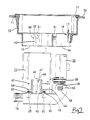
- the present embodiment is configured as described above, and it assembly is described below. Firstly, as shown in Figure 7, the frame 10 is attached to the attachment hole 71 of the panel 70 of the motor vehicle in the manner described above.
- the cover 60 is attached to the two sub-housings 20 and 30.
- the female terminal fittings, to which the ends of electric wires 74 are fixed, are housed within the cavities 22 and 32 of the sub-housings 20 and 30.
- the posterior end of the second sub-housing 30 is inserted into the protruding portion 62 of the cover 60, as shown by the arrow X in Figure 1.
- the two side plates of the protruding portion 62 rise over the tapered faces 36 of the locking protrusions 35 of the second sub-housing 30, these side plates opening resiliently and the second sub-housing 30 is pushed in up to a specified distance.
- the posterior end of the first sub-housing 20 is attached to the long and narrow portion 61 at the left side of the cover 60.
- the left and right locking members 64 grip the two guiding rails 41 of the stopping mechanism 40 as these two guiding rails 41 are pushed in. While this pushing-in is occurring, the locking members 64 rise over the tapered faces 26 of the locking protrusions 25 and move outwards.
- the first sub-housing 20 is pushed in until the posterior face thereof makes contact with the anterior edges of the side plates of the cover 60. Thereupon, the locking members 64 return resiliently to their original shape, and the locking protrusions 25 fit within the locking holes 65.
- the first sub-housing 20 is attached within the left side of the cover 60.
- the electric wires 74 which extend from the first sub-housing 20 are bent at approximately a right angle, pass through the cover 60 and extend out from an opening on the left side thereof (as viewed).
- the two sub-housings 20 and 30 and the cover 60 are attached at the harness assembly site in the manner described above. Then, in this state, they are transported to the site where they are attached to the motor vehicle.
- the two sub-housings 20 and 30, which have been unified by being attached to the cover 60, are inserted from the posterior (shown by the arrow in Figure 7) into the corresponding housing chambers 15 and 16 of the frame 10.
- the stopping plates 50 of the frame 10 approach the tips of the guiding rails 41 of the stopping mechanism 40. Then the stopping plates 50 are inserted between the two guiding rails 41 and the first sub-housing 20 is pushed in.
- the protruding member 46 of the stopping arm 45 engages with the stopping member 51, the tapered faces 47 and 52 mutually guide one another and, as the first sub-housing 20 is pushed in, the stopping arm 45 bends to the left (with respect of Figure 7) using the auxiliary stopping member 53 as the centre.
- the protrusions 42 of the guiding rails 41 make contact with the stopping plates 50 and the pushing-in is halted.
- the stopping arm 45 returns to its original straight state and the stopping member 51 is retained behind the posterior face of the protruding member 46.
- the stopping mechanism 40 engages with the stopping plates 50 in the same manner, and the protruding member 18 of the resilient stopping protrusion 17 fits into the stopping groove 38 of the second sub-housing 30.
- the two sub-housings 20 and 30 are housed within the corresponding housing chambers 15 and 16 in a state whereby they cannot move in an anterior or posterior direction.
- the cover 60 is attached to the posterior faces of the sub-housings 20 and 30.
- the cover 60 and the two sub-housings 20 and 30 can be attached in advance. Consequently, when the frame 10 is fixed to a motor vehicle or the like, the two sub-housings 20 and 30 are transported with the cover 60 being in an attached state therewith, and these sub-housings 20 and 30 need merely to be inserted and engaged with the frame 10. As a result, transportation to the motor vehicle assembly site is easier and, as assembly can be completed by inserting the pre-assembled sub-housings 20 and 30 into the frame 10, the assembly operation at the site is simplified.
Landscapes
- Connector Housings Or Holding Contact Members (AREA)
- Details Of Connecting Devices For Male And Female Coupling (AREA)
Abstract
Description
Claims (7)
- An electrical split connector comprising a frame (10) adapted to be fixed in a panel, and defining a plurality of chambers (15,16), a plurality of sub-connectors (29,30) having wires protruding therefrom and for insertion one each into said chambers (15,16), and a cover (60) adapted to enclose and guide wires of said sub-connectors (20,30) in a predetermined direction, characterised in that said sub-connectors (20,30) and cover (60) are provided with co-operating latch members (25, 35, 65, 66), thereby to form a sub-assembly for subsequent insertion into said frame (10).
- A connector according to claim 1 wherein said latch members comprise protrusions (25,35) of said sub-connectors (20,30) and co-operating openings (65,66) of said cover (60).
- A connector according to claim 2 wherein a plurality of said openings (65) are provided in resilient projections (64) of said cover (60).
- A connector according to claim 3 wherein said projections (64) extend in the direction of fitting of said cover (60) to said sub-connectors (20,30).
- A connector according to claim 4 wherein said projections (64) laterally engage guide surfaces (41) of one of said sub-connectors (20).
- A connector according to claim 5 wherein a pair of said projections (64) is provided, said pair engaging either side of a corresponding guide member (40) having guide surfaces (41) at opposite sides thereof.
- A method of inserting a plurality of sub-connectors into a panel and comprising the steps of:fixing a frame in an aperture of a panel;latching a plurality of sub-connectors to a cover to form a sub-assembly, the cover enclosing and guiding wires protruding from the respective sub-connectors; andinserting said sub-assembly into said frame.
Applications Claiming Priority (2)
| Application Number | Priority Date | Filing Date | Title |
|---|---|---|---|
| JP11121646A JP2000311741A (en) | 1999-04-28 | 1999-04-28 | Split connector |
| JP12164699 | 1999-04-28 |
Publications (3)
| Publication Number | Publication Date |
|---|---|
| EP1049211A2 true EP1049211A2 (en) | 2000-11-02 |
| EP1049211A3 EP1049211A3 (en) | 2003-06-25 |
| EP1049211B1 EP1049211B1 (en) | 2008-05-14 |
Family
ID=14816415
Family Applications (1)
| Application Number | Title | Priority Date | Filing Date |
|---|---|---|---|
| EP00303562A Expired - Lifetime EP1049211B1 (en) | 1999-04-28 | 2000-04-27 | Multi-piece connector |
Country Status (4)
| Country | Link |
|---|---|
| US (1) | US6575794B1 (en) |
| EP (1) | EP1049211B1 (en) |
| JP (1) | JP2000311741A (en) |
| DE (1) | DE60038843D1 (en) |
Cited By (2)
| Publication number | Priority date | Publication date | Assignee | Title |
|---|---|---|---|---|
| WO2014184283A1 (en) * | 2013-05-17 | 2014-11-20 | Delphi International Operations Luxembourg S.À R.L. | Connector for motor vehicles |
| WO2020144005A1 (en) * | 2019-01-11 | 2020-07-16 | Phoenix Contact E-Mobility Gmbh | Plug connector part having a connector part to be connected to a housing part |
Families Citing this family (19)
| Publication number | Priority date | Publication date | Assignee | Title |
|---|---|---|---|---|
| DE10017335B4 (en) * | 2000-04-07 | 2011-03-10 | Conti Temic Microelectronic Gmbh | Electronic module |
| US7121888B2 (en) * | 2002-07-10 | 2006-10-17 | 3M Innovative Properties Company | Multiple wire cable connector |
| GB0325120D0 (en) * | 2003-10-28 | 2003-12-03 | Smith & Nephew | Apparatus with actives |
| KR101479113B1 (en) | 2006-01-06 | 2015-01-07 | 미쓰비시 엔지니어링-플라스틱스 코포레이션 | Aromatic polyarbonate resin composition for lightguide plate and lightguide plate |
| US8109883B2 (en) | 2006-09-28 | 2012-02-07 | Tyco Healthcare Group Lp | Cable monitoring apparatus |
| US8668651B2 (en) | 2006-12-05 | 2014-03-11 | Covidien Lp | ECG lead set and ECG adapter system |
| US8038484B2 (en) | 2007-12-11 | 2011-10-18 | Tyco Healthcare Group Lp | ECG electrode connector |
| USD737979S1 (en) | 2008-12-09 | 2015-09-01 | Covidien Lp | ECG electrode connector |
| US7845989B2 (en) * | 2009-02-09 | 2010-12-07 | Sumitomo Wiring Systems, Ltd. | Connector |
| US8694080B2 (en) | 2009-10-21 | 2014-04-08 | Covidien Lp | ECG lead system |
| JP5091983B2 (en) * | 2010-06-16 | 2012-12-05 | 矢崎総業株式会社 | Lever fitting type connector |
| CA2746944C (en) | 2010-07-29 | 2018-09-25 | Tyco Healthcare Group Lp | Ecg adapter system and method |
| JP5614220B2 (en) * | 2010-10-08 | 2014-10-29 | 住友電装株式会社 | Wire harness wiring structure with connector holder |
| WO2013013370A1 (en) | 2011-07-22 | 2013-01-31 | Tyco Healthcare Group Lp | Ecg electrode connector |
| US8634901B2 (en) | 2011-09-30 | 2014-01-21 | Covidien Lp | ECG leadwire system with noise suppression and related methods |
| USD771818S1 (en) | 2013-03-15 | 2016-11-15 | Covidien Lp | ECG electrode connector |
| EP2967396B1 (en) | 2013-03-15 | 2019-02-13 | Kpr U.S., Llc | Electrode connector with a conductive member |
| US9408546B2 (en) | 2013-03-15 | 2016-08-09 | Covidien Lp | Radiolucent ECG electrode system |
| CN207037650U (en) * | 2017-08-10 | 2018-02-23 | 清远市亿源通光电科技有限公司 | A kind of elastic piece structure and adapter |
Family Cites Families (14)
| Publication number | Priority date | Publication date | Assignee | Title |
|---|---|---|---|---|
| JP2605189B2 (en) * | 1991-08-27 | 1997-04-30 | 矢崎総業株式会社 | Connector connection device |
| US5238426A (en) * | 1992-06-11 | 1993-08-24 | At&T Bell Laboratories | Universal patch panel for communications use in buildings |
| JPH0660936A (en) * | 1992-08-05 | 1994-03-04 | Yazaki Corp | Combination connector |
| JP2671729B2 (en) * | 1992-09-29 | 1997-10-29 | 住友電装株式会社 | Connector device |
| JP2567848Y2 (en) * | 1992-10-08 | 1998-04-08 | 住友電装株式会社 | connector |
| US5328388A (en) * | 1993-05-28 | 1994-07-12 | Yazaki Corporation | Modular electrical connector |
| JP2962156B2 (en) * | 1994-08-09 | 1999-10-12 | 住友電装株式会社 | Split connector |
| GB2292642B (en) * | 1994-08-22 | 1998-06-03 | Sumitomo Wiring Systems | Connector |
| GB2293053B (en) | 1994-09-06 | 1998-10-21 | Sumitomo Wiring Systems | Divisional connector |
| JPH0878097A (en) * | 1994-09-06 | 1996-03-22 | Sumitomo Wiring Syst Ltd | Split connector |
| JP3322788B2 (en) * | 1996-01-29 | 2002-09-09 | 住友電装株式会社 | Connector housing |
| US5931688A (en) * | 1996-09-16 | 1999-08-03 | The Whitaker Company | Self docketing electrical connector assembly |
| JPH11250973A (en) * | 1998-03-04 | 1999-09-17 | Yazaki Corp | Connector locking structure |
| JPH11260468A (en) * | 1998-03-10 | 1999-09-24 | Yazaki Corp | Connector |
-
1999
- 1999-04-28 JP JP11121646A patent/JP2000311741A/en active Pending
-
2000
- 2000-04-27 DE DE60038843T patent/DE60038843D1/en not_active Expired - Fee Related
- 2000-04-27 US US09/559,877 patent/US6575794B1/en not_active Expired - Fee Related
- 2000-04-27 EP EP00303562A patent/EP1049211B1/en not_active Expired - Lifetime
Cited By (7)
| Publication number | Priority date | Publication date | Assignee | Title |
|---|---|---|---|---|
| WO2014184283A1 (en) * | 2013-05-17 | 2014-11-20 | Delphi International Operations Luxembourg S.À R.L. | Connector for motor vehicles |
| FR3005796A1 (en) * | 2013-05-17 | 2014-11-21 | Delphi Int Operations Luxembourg Sarl | CONNECTOR FOR MOTOR VEHICLES |
| CN105393410A (en) * | 2013-05-17 | 2016-03-09 | 德尔福国际业务卢森堡公司 | Connector for motor vehicles |
| CN105393410B (en) * | 2013-05-17 | 2018-07-03 | 德尔福国际业务卢森堡公司 | The connector of motor vehicle |
| WO2020144005A1 (en) * | 2019-01-11 | 2020-07-16 | Phoenix Contact E-Mobility Gmbh | Plug connector part having a connector part to be connected to a housing part |
| BE1026967B1 (en) * | 2019-01-11 | 2020-08-13 | Phoenix Contact E-Mobility Gmbh | Plug connector part with a connector part to be connected to a housing part |
| US11749934B2 (en) | 2019-01-11 | 2023-09-05 | Phoenix Contact E-Mobility Gmbh | Plug connector part having a connector part to be connected to a housing part |
Also Published As
| Publication number | Publication date |
|---|---|
| DE60038843D1 (en) | 2008-06-26 |
| EP1049211A3 (en) | 2003-06-25 |
| EP1049211B1 (en) | 2008-05-14 |
| JP2000311741A (en) | 2000-11-07 |
| US6575794B1 (en) | 2003-06-10 |
Similar Documents
| Publication | Publication Date | Title |
|---|---|---|
| EP1049211B1 (en) | Multi-piece connector | |
| US5755595A (en) | Shielded electrical connector | |
| EP0907989B1 (en) | Shielded electrical connector | |
| US5380220A (en) | Connector | |
| US5902155A (en) | Electrical connector assembly | |
| US8333613B2 (en) | Header assembly | |
| US5252096A (en) | Connector | |
| EP0971442A1 (en) | A connector with a side type retainer | |
| EP1780845A1 (en) | Connector mounting receptacles | |
| JP2002246107A (en) | connector | |
| EP0125786A2 (en) | Electrical connector assembly | |
| US6435891B1 (en) | Mechanically assisted blind mate electrical connector | |
| JP2510465Y2 (en) | Connector housing with combined and united structure | |
| JPH10112355A (en) | Rattling prevention structure for electrical connectors | |
| JPH0650262U (en) | Shielded connector | |
| US5372523A (en) | Body mounting type electrical connector | |
| US6071148A (en) | Seal retention member | |
| US5957709A (en) | Electrical connector coupling | |
| US20250105545A1 (en) | Header connector with busbar assembly | |
| EP1261070A2 (en) | A terminal fitting and a connector provided therewith | |
| JPH05290918A (en) | Electrical connector | |
| JP2592639Y2 (en) | ID connector | |
| US6315619B1 (en) | Three part electrical connector with preventation latching means | |
| JPH1116625A (en) | Double locking member for connector | |
| US6669508B2 (en) | Connector |
Legal Events
| Date | Code | Title | Description |
|---|---|---|---|
| PUAI | Public reference made under article 153(3) epc to a published international application that has entered the european phase |
Free format text: ORIGINAL CODE: 0009012 |
|
| 17P | Request for examination filed |
Effective date: 20000519 |
|
| AK | Designated contracting states |
Kind code of ref document: A2 Designated state(s): AT BE CH CY DE DK ES FI FR GB GR IE IT LI LU MC NL PT SE |
|
| AX | Request for extension of the european patent |
Free format text: AL;LT;LV;MK;RO;SI |
|
| PUAL | Search report despatched |
Free format text: ORIGINAL CODE: 0009013 |
|
| AK | Designated contracting states |
Designated state(s): AT BE CH CY DE DK ES FI FR GB GR IE IT LI LU MC NL PT SE |
|
| AX | Request for extension of the european patent |
Extension state: AL LT LV MK RO SI |
|
| AKX | Designation fees paid |
Designated state(s): DE FR GB IT |
|
| GRAP | Despatch of communication of intention to grant a patent |
Free format text: ORIGINAL CODE: EPIDOSNIGR1 |
|
| GRAS | Grant fee paid |
Free format text: ORIGINAL CODE: EPIDOSNIGR3 |
|
| GRAA | (expected) grant |
Free format text: ORIGINAL CODE: 0009210 |
|
| AK | Designated contracting states |
Kind code of ref document: B1 Designated state(s): DE FR GB IT |
|
| REG | Reference to a national code |
Ref country code: GB Ref legal event code: FG4D |
|
| RIN1 | Information on inventor provided before grant (corrected) |
Inventor name: NAKAMURA, HIDETOC/O SUMITOMO WIRING SYSTEMS, LTD., |
|
| REF | Corresponds to: |
Ref document number: 60038843 Country of ref document: DE Date of ref document: 20080626 Kind code of ref document: P |
|
| PLBE | No opposition filed within time limit |
Free format text: ORIGINAL CODE: 0009261 |
|
| STAA | Information on the status of an ep patent application or granted ep patent |
Free format text: STATUS: NO OPPOSITION FILED WITHIN TIME LIMIT |
|
| 26N | No opposition filed |
Effective date: 20090217 |
|
| PG25 | Lapsed in a contracting state [announced via postgrant information from national office to epo] |
Ref country code: IT Free format text: LAPSE BECAUSE OF FAILURE TO SUBMIT A TRANSLATION OF THE DESCRIPTION OR TO PAY THE FEE WITHIN THE PRESCRIBED TIME-LIMIT Effective date: 20080514 |
|
| GBPC | Gb: european patent ceased through non-payment of renewal fee |
Effective date: 20090427 |
|
| REG | Reference to a national code |
Ref country code: FR Ref legal event code: ST Effective date: 20091231 |
|
| PG25 | Lapsed in a contracting state [announced via postgrant information from national office to epo] |
Ref country code: DE Free format text: LAPSE BECAUSE OF NON-PAYMENT OF DUE FEES Effective date: 20091103 |
|
| PG25 | Lapsed in a contracting state [announced via postgrant information from national office to epo] |
Ref country code: GB Free format text: LAPSE BECAUSE OF NON-PAYMENT OF DUE FEES Effective date: 20090427 Ref country code: FR Free format text: LAPSE BECAUSE OF NON-PAYMENT OF DUE FEES Effective date: 20091222 |