EP1049016A2 - Disk subsystems and their integrated system - Google Patents
Disk subsystems and their integrated system Download PDFInfo
- Publication number
- EP1049016A2 EP1049016A2 EP00103718A EP00103718A EP1049016A2 EP 1049016 A2 EP1049016 A2 EP 1049016A2 EP 00103718 A EP00103718 A EP 00103718A EP 00103718 A EP00103718 A EP 00103718A EP 1049016 A2 EP1049016 A2 EP 1049016A2
- Authority
- EP
- European Patent Office
- Prior art keywords
- data
- subsystem
- gateway
- disk
- gateway subsystem
- Prior art date
- Legal status (The legal status is an assumption and is not a legal conclusion. Google has not performed a legal analysis and makes no representation as to the accuracy of the status listed.)
- Granted
Links
Images


Classifications
-
- G—PHYSICS
- G06—COMPUTING OR CALCULATING; COUNTING
- G06F—ELECTRIC DIGITAL DATA PROCESSING
- G06F11/00—Error detection; Error correction; Monitoring
- G06F11/07—Responding to the occurrence of a fault, e.g. fault tolerance
- G06F11/16—Error detection or correction of the data by redundancy in hardware
- G06F11/20—Error detection or correction of the data by redundancy in hardware using active fault-masking, e.g. by switching out faulty elements or by switching in spare elements
- G06F11/2053—Error detection or correction of the data by redundancy in hardware using active fault-masking, e.g. by switching out faulty elements or by switching in spare elements where persistent mass storage functionality or persistent mass storage control functionality is redundant
- G06F11/2056—Error detection or correction of the data by redundancy in hardware using active fault-masking, e.g. by switching out faulty elements or by switching in spare elements where persistent mass storage functionality or persistent mass storage control functionality is redundant by mirroring
- G06F11/2071—Error detection or correction of the data by redundancy in hardware using active fault-masking, e.g. by switching out faulty elements or by switching in spare elements where persistent mass storage functionality or persistent mass storage control functionality is redundant by mirroring using a plurality of controllers
- G06F11/2074—Asynchronous techniques
-
- G—PHYSICS
- G06—COMPUTING OR CALCULATING; COUNTING
- G06F—ELECTRIC DIGITAL DATA PROCESSING
- G06F11/00—Error detection; Error correction; Monitoring
- G06F11/07—Responding to the occurrence of a fault, e.g. fault tolerance
- G06F11/16—Error detection or correction of the data by redundancy in hardware
- G06F11/20—Error detection or correction of the data by redundancy in hardware using active fault-masking, e.g. by switching out faulty elements or by switching in spare elements
- G06F11/2053—Error detection or correction of the data by redundancy in hardware using active fault-masking, e.g. by switching out faulty elements or by switching in spare elements where persistent mass storage functionality or persistent mass storage control functionality is redundant
- G06F11/2056—Error detection or correction of the data by redundancy in hardware using active fault-masking, e.g. by switching out faulty elements or by switching in spare elements where persistent mass storage functionality or persistent mass storage control functionality is redundant by mirroring
- G06F11/2064—Error detection or correction of the data by redundancy in hardware using active fault-masking, e.g. by switching out faulty elements or by switching in spare elements where persistent mass storage functionality or persistent mass storage control functionality is redundant by mirroring while ensuring consistency
-
- G—PHYSICS
- G06—COMPUTING OR CALCULATING; COUNTING
- G06F—ELECTRIC DIGITAL DATA PROCESSING
- G06F11/00—Error detection; Error correction; Monitoring
- G06F11/07—Responding to the occurrence of a fault, e.g. fault tolerance
- G06F11/16—Error detection or correction of the data by redundancy in hardware
- G06F11/20—Error detection or correction of the data by redundancy in hardware using active fault-masking, e.g. by switching out faulty elements or by switching in spare elements
- G06F11/2053—Error detection or correction of the data by redundancy in hardware using active fault-masking, e.g. by switching out faulty elements or by switching in spare elements where persistent mass storage functionality or persistent mass storage control functionality is redundant
- G06F11/2056—Error detection or correction of the data by redundancy in hardware using active fault-masking, e.g. by switching out faulty elements or by switching in spare elements where persistent mass storage functionality or persistent mass storage control functionality is redundant by mirroring
- G06F11/2071—Error detection or correction of the data by redundancy in hardware using active fault-masking, e.g. by switching out faulty elements or by switching in spare elements where persistent mass storage functionality or persistent mass storage control functionality is redundant by mirroring using a plurality of controllers
- G06F11/2076—Synchronous techniques
Definitions
- the present invention relates to external storage devices for storing data in a computer system and to their integrated system, and more particularly to remote copy techniques for mirroring data between remote external storage devices (disk subsystems) without involving an upper hierarchical apparatus or host computer, by interconnecting remote external storage devices and other remote external storage devices.
- the disk subsystem is herein intended to mean a control unit for controlling data transfer to and from an upper hierarchical apparatus and a storage device having disks for storing data or a storage device having an internal buffer.
- the remote copy function is mainly classified into two types, a synchronous type and an asynchronous type.
- the synchronous type executes the following process sequence.
- a disk subsystem is instructed by a host computer (upper hierarchical apparatus) of a main center to renew (write) data and if the disk subsystem is assigned the remote copy function, a renewal process completion notice is issued to the host computer of the main center only after the instructed data renewal (write) is completed for a corresponding disk subsystem in a remote center.
- a time delay (transmission time and the like) is generated in accordance with a geographical distance between the main center and remote center and the performance of a data transmission line therebetween. If the transmission time of the synchronous type is taken into consideration, several tens Km is a practical limit of a distance to a remote site.
- the data contents in disk subsystems in the main and remote centers are always consistent from a macro viewpoint. Therefore, even if the function of the main center is lost by accidents or the like, the data contents immediately before the accidents are perfectly retained in the disk subsystems of the remote center and the process can be resumed quickly at the remote center.
- the term "always consistent from the macro viewpoint" means that during the execution of the synchronous type function, although the data contents may be different in terms of a process time ( ⁇ sec, msec) of magnetic disk devices and electronic circuits, the data contents are always the same at the time of data renewal completion. This is because the renewal process at the main center cannot be completed unless the renewal data is completely reflected upon the remote center. Therefore, in some cases, particularly if a distance between the main and remote centers is long and the data transmission line is congested, the access performance to a disk subsystem in the main center is considerably degraded.
- the asynchronous type executes the following process sequence.
- a disk subsystem is instructed by a host computer of a main center to renew (write) data and even if this data is to be remotely copied
- a renewal process completion notice is issued to the host computer of the main center immediately after the data renewal process for the disk subsystem in the main center is completed, to thereafter execute the data renewal (reflection) of the disk subsystem in the remote center, asynchronously with the data renewal in the main center. Since the data renewal is completed in a process time required by the main center, there is no transmission delay time or the like to be caused by storing the data in the remote center.
- the data contents in a disk subsystem of the remote center are not always consistent with those in the main center. Therefore, if the function of the main center is lost by accidents or the like, the data still not reflected upon the remote center is lost. However, an access performance of a disk subsystem in the main center can be maintained at the level when the remote copy function is not executed.
- a database or the like is generally constituted of a main body of the database and various log and control information directly associated with the main body.
- data is renewed, not only the database main body but also the log and control information is renewed to maintain the system integrity. Therefore, if the renewal order is not kept, the integrity of information regarding the renewal order is also lost, and at the worst the whole of the database may be destructed.
- the host computer when the host computer instructs the disk subsystem to renew data, it is common that the host computer adds renewal order information such as a time stamp to the data to make the corresponding disk subsystem in the remote center execute a renewal data reflection process in accordance with the added information.
- renewal order information such as a time stamp
- Each of a main center and a remote center is provided with a disk subsystem serving as a gateway (hereinafter called a gateway subsystem) which is connected to a data transmission line. All disk subsystems in both the centers to which a remote copy is executed, are connected to the corresponding gateway subsystem of each center.
- a gateway subsystem serving as a gateway
- a volume of the disk subsystem in the main center to be remotely copied and a desired volume of the gateway subsystem in the main center are coupled by a synchronous type remote function to mirror data. If a system process time delay or the like can be neglected between the volume of the disk subsystem in the main center to be remotely copied and the volume of the gateway subsystem in the main center, data consistency can be retained.
- Data is mirrored between volumes of the gateway subsystems of the main and remote centers through asynchronous remote copy.
- the gateway subsystem of the main center sends renewal data to the gateway subsystem of the remote center in accordance with the renewal order of volumes of disk subsystems of the main center, whereas the gateway subsystem of the remote center reflects the renewal data upon corresponding volumes of the remote center in accordance with the reception order of the renewal data.
- Data is mirrored between the volume of the gateway subsystem of the remote center and the volume of each disk subsystem through synchronous remote copy. Data same as from a macro viewpoint is always stored in the volume of the gateway subsystem of the remote center and in the volume of the disk subsystem to be remotely copied.
- the gateway subsystem stores data in the volume to be remotely copied, in a buffer memory of the gateway subsystem. Since the gateway subsystem has the buffer memory, generally an area for storing data in the gateway subsystem is not necessarily required. However, if there is an available area in the gateway subsystem, this area can be utilized for data transfer via the transmission line, depending upon the capacity of the transmission line.
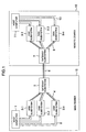
- Fig. 1 shows an example of the structure of a system embodying this invention and allowing data to be mirrored between arbitrary two data centers among a plurality of data centers each provided with a general computer system.
- One or a plurality of disk subsystems in a main center and one or a plurality of disk subsystems in a remote center are interconnected via gateway subsystems without involving the host computers, to realize a remote copy system for mirroring data between both the centers.
- a central processing unit (host computer) 1 is connected via interface cables 2 to disk subsystems 3-1, 3-2, ..., 3-n.
- the disk subsystems 3-1, 3-2, ..., 3-n store data to be referred to, or renewed, by the host computer 1.
- the gateway subsystem 5 is connected via interface cables 4 to the disk subsystems 3-1 to 3-n.
- the gateway subsystem 7 is provided in the remote center 13 and connected via an interface cable 6 to the gateway subsystem 5 of the main center 12.
- the interface cable 6 is connectable to a general communication line. In this embodiment, therefore, the interface cable 6 is intended to include such a function.
- the disk subsystem 3-1 or the like When the host computer 1 issues a data write request to a disk subsystem 3-1 or the like, the disk subsystem 3-1 or the like writes the data in its buffer memory. Synchronously with this timing the disk subsystem 3-1 or the like issues a data write request to the gateway subsystem 5.
- the gateway subsystem 5 Upon reception of this write request, the gateway subsystem 5 writes the data in its buffer memory. Asynchronously with the data write in the buffer memory of the gateway subsystem 5, the gateway subsystem 5 issues a data write request to the gateway subsystem 7 at the remote site. It is essential to use only one gateway subsystem 5 irrespective of how many disk subsystems 3-1 to 3-n are used.
- the gateway subsystem 7 stores data supplied from the gateway subsystem 5 in its buffer memory, in the order of data write requests. It is essential to use only one gateway subsystem 7.
- Disk subsystems 9-1, 9-2, ..., 9-n are connected via interface cables 8 to the gateway subsystem 7.
- a data write request is issued from the main center 12 to the gateway subsystem 7, synchronously with this timing the gateway subsystem 7 writes the data therein and in the disk subsystem 9-1.
- Remote copy is therefore executed by sequentially issuing a write request to a subsystem and then to the next subsystem.
- a data write request is issued from the host computer 1 to one or a plurality of disk subsystems 3-1 to 3-n, the same data is loaded in one or a plurality of disk subsystems 9-1 to 9-n of the remote center 13.
- Arrows shown in Fig. 1 indicate the flow of the data instructed to be written by the host computer 1.
- the host computer 11 is connected via interface cables 10 to the disk subsystems 9-1 to 9-n, and is a central processing unit which executes data reference and renewal relative to the disk subsystem 9-1 or the like.
- the host computer 11 can operate as an alternative to the host computer 1.
- the host computer 11 can execute a process different from that of the host computer 1 of the main center 12 by using data stored in the disk subsystem 9-1 or the like, independently from the operation of the host computer 1. However, if the host computer 11 does not execute a process by using the disk subsystem 9-1, this host computer 11 is unnecessary.
- a volume, a data set and a disk subsystem which store data to be mirrored are preselected by an administrator.
- the relation between the volume, data set and disk subsystem in which the data is stored and a volume, a data set and a disk subsystem which store a copy of the data, is preset to the disk subsystems by the administrator from the host computers.
- a write destination of data to be copied is determined sequentially between respective disk subsystems described above. For example, when data is written in a volume of the disk subsystem 3-1, it is set in such a manner that in which volume of the gateway subsystem 5 the data is written from the disk subsystem 3-1, then in which volume of the gateway subsystem 7 the data is written from the gateway subsystem 5, lastly in which volume of the disk subsystem 9-1 the data is written from the gateway subsystem 7.
- Such settings are provided for each disk subsystem including the gateway disk subsystem.
- the serial number and volume of each disk subsystem are used. For example, a volume A of the disk subsystem 3-1 is set to a volume B of the gateway subsystem 5, the volume B of the gateway subsystem 5 is set to a volume C of the gateway subsystem 7, and the volume C of the gateway subsystem 7 is set to a volume D of the disk subsystem 9-1. In this manner, the data written in the volume A of the disk subsystem 3-1 is copied to the volume D of the disk subsystem 9-1. This setting is conducted for all volumes.
- Such preselect and preset may be effected by using a console or a service processor without using the host computer, if the disk subsystem can be connected to or provided with its console or service processor.
- the flow chart shown in Fig. 2 illustrates the operation assuming that the host computer is used for such preselect and preset.
- a specific address indicating the volume or disk subsystem may be designated, or the volume or disk subsystem in an arbitrary address range may be selected by using a control program in the disk subsystem.
- Path setting and pair setting are used as an example of initial setting (Fig. 2, 201).
- a write command As the host computer 1 (Fig. 1) issues a data write request (hereinafter called a write command) to the disk subsystem 3-1, 3-2, ..., 3-n (211) (Fig. 2, 202), the disk subsystem 3-1, 3-2, ..., 3-n executes a data load process for loading the write data therein in response to the write command, and also issues a write command for the data to the gateway subsystem 5 (212) (203).
- the write command is a command for transferring an instruction of data write and the write data itself.
- the gateway subsystem 5 Upon reception of the write command, the gateway subsystem 5 executes a process corresponding to the write command (204). After the gateway subsystem completes a data load process for loading the data in its buffer memory, it notifies a process completion to the disk subsystem 3-1, 3-2, ..., 3-2 (211). A write command number is assigned to each write command in the order of the process completion (205), and at the timing determined basing upon the processing capability of the gateway subsystem 5, the write command assigned the write command number is issued to the gateway subsystem 7 (213) in the order of the write command number (206).
- the disk subsystem 3-1, 3-2, ..., 3-n completes a process for the write command issued from the host computer 1, i.e., completes a data load process for loading the data therein, and receives a write process completion notice from the gateway subsystem 5 (212) (221), the disk subsystem supplies a write command process completion notice to the host computer 1 (222).
- the gateway subsystem 7 (213) confirms, from the write command numbers assigned to respective write commands issued from the gateway subsystem 5 (212), whether the write commands have been received in the order of the assigned write command numbers. Thereafter, the gateway subsystem executes the processes corresponding to the write commands, i.e., executes a data load process (301) for loading the data in its buffer memory. Thereafter, a write command corresponding to the loaded data is issued to the corresponding disk subsystem 9 (311) (302). Upon reception of the write command issued from the gateway subsystem 7, the disk subsystem 9 (311) executes a process corresponding to the write command, i.e., executes a data load process for loading the data therein (303).
- the disk subsystem 9-1, 9-2,..., 9-n (311) completes the process corresponding to the write command, i.e., completes the data load process for loading the data in its buffer memory, it supplies a process completion notice to the gateway subsystem 7 (321).
- the gateway subsystem 7 (213) completes the data load process for loading the data therein and receives the write process completion notice from the disk subsystem 9-1, 9-2,..., 9-n, the gateway subsystem 7 supplies a process completion notice for the write command to the gateway subsystem 5 (322).
- data written by the host computer 1 is mirrored between the disk subsystem 3-1, 3-2, ..., 3-n and the gateway subsystem 5 and is maintained consistent from a macro viewpoint.
- the gateway subsystem 5 adds information (serial number) to the data in order to hold the renewal order.
- a buffer area for temporarily storing write data is provided at each gateway subsystem in order to prevent an overflow of a buffer memory for a general transmission line.
- Data stored in the buffer area of the subsystem is sent from the main center 12 to the remote center 13 via the transmission line, and to the gateway subsystem via the buffer area on the side of the remote center 12.
- Fig. 5 shows the structure of the gateway subsystem 5.
- the structure of the gateway subsystem 7 is the same as the gateway subsystem 5.
- the gateway subsystem 5 has: an interface control unit 11 for data (including information) transfer to and from the disk subsystem 3-1 or the like and the gateway subsystem 7; a data buffer 12 for temporarily storing the data; a magnetic disk drive 13 as a storage medium for storing the data; a control memory for storing remote copy status information (as to which volume of which disk subsystem is written to which volume of the gateway subsystem 5, as to which volume of the gateway subsystem 5 is written in which volume of the gateway subsystem, and the like); a microprocessor 14 for controlling transfer of these data; a service processor panel 15 allowing a user to set how the remote copy is executed; and a disk array subsystem control unit 17 for controlling these components.
- an interface control unit 11 for data (including information) transfer to and from the disk subsystem 3-1 or the like and the gateway subsystem 7
- a data buffer 12 for temporarily storing the data
- a magnetic disk drive 13 as a storage medium for storing the data
- a control memory for storing remote copy status information (as to which
- the data buffer 12 is provided at the gateway subsystem 12, this data buffer 12 is not necessary if a cache memory capable of performing a similar function to the data buffer 12 is provided, because the cache memory can function as the data buffer 12. In this specification, therefore, the data buffer 12 is intended to be inclusive of such a cache memory.
- the control memory 16 is provided at the gateway subsystem 5, this control memory 16 is not necessary if a remote copy control information storage unit capable of performing a similar function to the control memory 16 is provided, because the remote copy information storage unit can function as the control memory 16. In this specification, therefore, the control memory 16 is intended to be inclusive of such a remote copy information storage unit.
- an asynchronous type remote copy system can be realized which can ensure the data renewal order and data integrity by using the functions of disk subsystems without incorporating new software and which is easy to be incorporated and free from degradation of the process performance of the main center.
- a storage area of the subsystem can be used depending upon the communication capacity of the transmission line so that a burden of a line subscription fee of a customer can be reduced.
Landscapes
- Engineering & Computer Science (AREA)
- Theoretical Computer Science (AREA)
- Quality & Reliability (AREA)
- Physics & Mathematics (AREA)
- General Engineering & Computer Science (AREA)
- General Physics & Mathematics (AREA)
- Information Retrieval, Db Structures And Fs Structures Therefor (AREA)
- Techniques For Improving Reliability Of Storages (AREA)
- Hardware Redundancy (AREA)
Abstract
Description
Claims (11)
- A system having a plurality of subsystems (3, 9) connected to an upper hierarchical apparatus (1, 11), comprising:a gateway subsystem (5, 7) having a buffer memory for storing data supplied from said plurality of subsystems and an interface for connection to another system having other subsystems for writing the data therein.
- A system according to claim 1, wherein said gateway subsystem stores data supplied from said plurality of subsystems and writes data into the other system, asynchronously.
- A system according to claim 1, wherein said gateway subsystem adds order information of data to be transferred to the other system.
- An integrated system comprising:the other system (13) having a second gateway subsystem for receiving a write request sent from said gateway subsystem and a plurality of subsystems connected to the second gateway subsystem; andthe system (12) recited in claim 1.
- An integrated system according to claim 4, wherein the other system is located at a remote site.
- An integrated system according to claim 4, wherein the other system is connected by a communication line.
- An integrated system according to claim 1 or 6, wherein the subsystem is a disk subsystem.
- A data copy method comprising the steps of:receiving a write request for data from an upper hierarchical apparatus (1) at a subsystem (3) of a first subsystem group;writing the data in a first gateway subsystem (5);writing the data written in the first gateway subsystem in a second gateway subsystem (7); andwriting the data in a subsystem (9) of a second subsystem group from the second gateway subsystem.
- A data copy method according to claim 8, wherein writing data from the upper hierarchical apparatus into the subsystem and writing data from the subsystem into the first gateway subsystem are executed synchronously.
- A data copy method according to claim 8, wherein writing data from the subsystem into the first gateway subsystem and writing data from the first gateway subsystem into the subsystem of the second subsystem group are executed asynchronously.
- A data copy method according to claim 10, further comprising a step of adding a number to data in the order of data write into the first gateway subsystem.
Applications Claiming Priority (2)
| Application Number | Priority Date | Filing Date | Title |
|---|---|---|---|
| JP11117670A JP2000305856A (en) | 1999-04-26 | 1999-04-26 | Disk subsystems and their integrated systems |
| JP11767099 | 1999-04-26 |
Publications (3)
| Publication Number | Publication Date |
|---|---|
| EP1049016A2 true EP1049016A2 (en) | 2000-11-02 |
| EP1049016A3 EP1049016A3 (en) | 2006-07-26 |
| EP1049016B1 EP1049016B1 (en) | 2010-04-07 |
Family
ID=14717385
Family Applications (1)
| Application Number | Title | Priority Date | Filing Date |
|---|---|---|---|
| EP00103718A Expired - Lifetime EP1049016B1 (en) | 1999-04-26 | 2000-02-22 | Disk subsystems for mirroring, their integrated system and corresponding mirroring method |
Country Status (4)
| Country | Link |
|---|---|
| US (2) | US7167902B1 (en) |
| EP (1) | EP1049016B1 (en) |
| JP (1) | JP2000305856A (en) |
| DE (1) | DE60044109D1 (en) |
Cited By (2)
| Publication number | Priority date | Publication date | Assignee | Title |
|---|---|---|---|---|
| US7055011B2 (en) | 2003-11-26 | 2006-05-30 | Hitachi, Ltd. | Remote copy network |
| EP1283469A3 (en) * | 2001-08-08 | 2008-07-16 | Hitachi, Ltd. | Data storage system with remote copy control method |
Families Citing this family (28)
| Publication number | Priority date | Publication date | Assignee | Title |
|---|---|---|---|---|
| US7114049B2 (en) | 1997-01-08 | 2006-09-26 | Hitachi, Ltd. | Adaptive remote copy in a heterogeneous environment |
| JP2000305856A (en) * | 1999-04-26 | 2000-11-02 | Hitachi Ltd | Disk subsystems and their integrated systems |
| US7167962B2 (en) | 1999-08-19 | 2007-01-23 | Hitachi, Ltd. | Remote copy for a storage controller with reduced data size |
| JP4044717B2 (en) * | 2000-03-31 | 2008-02-06 | 株式会社日立製作所 | Data duplication method and data duplication system for storage subsystem |
| US6938122B2 (en) | 2001-01-23 | 2005-08-30 | Emc Corporation | Remote mirroring in a switched environment |
| US7194590B2 (en) | 2001-02-28 | 2007-03-20 | Hitachi, Ltd. | Three data center adaptive remote copy |
| US7213114B2 (en) | 2001-05-10 | 2007-05-01 | Hitachi, Ltd. | Remote copy for a storage controller in a heterogeneous environment |
| US7143252B2 (en) | 2001-05-10 | 2006-11-28 | Hitachi, Ltd. | Storage apparatus system and method of data backup |
| US7328353B2 (en) * | 2002-02-14 | 2008-02-05 | Matsushita Electric Industrial Co., Ltd. | Content distribution system |
| JP2004013367A (en) | 2002-06-05 | 2004-01-15 | Hitachi Ltd | Data storage subsystem |
| JP2004086721A (en) | 2002-08-28 | 2004-03-18 | Nec Corp | Data reproducing system, relay system, data transmission/receiving method, and program for reproducing data in storage |
| JP2004310427A (en) * | 2003-04-07 | 2004-11-04 | Nec Software Tohoku Ltd | Data transfer system, method, and program between storage area networks |
| US7065589B2 (en) * | 2003-06-23 | 2006-06-20 | Hitachi, Ltd. | Three data center remote copy system with journaling |
| US7139887B2 (en) * | 2003-12-31 | 2006-11-21 | Veritas Operating Corporation | Coordinated storage management operations in replication environment |
| US7600087B2 (en) * | 2004-01-15 | 2009-10-06 | Hitachi, Ltd. | Distributed remote copy system |
| JP4382602B2 (en) * | 2004-04-23 | 2009-12-16 | 株式会社日立製作所 | Remote copy system |
| JP4452557B2 (en) | 2004-05-27 | 2010-04-21 | 株式会社日立製作所 | Remote copy with WORM guarantee |
| JP4376750B2 (en) * | 2004-10-14 | 2009-12-02 | 株式会社日立製作所 | Computer system |
| JP4431022B2 (en) * | 2004-10-18 | 2010-03-10 | 株式会社日立製作所 | Computer system and control method thereof |
| JP2007072847A (en) * | 2005-09-08 | 2007-03-22 | Nec Corp | Information processing system, separation hiding device, separation control method and program |
| JP2007128335A (en) * | 2005-11-04 | 2007-05-24 | Nec Corp | Replication arbitration device, method and program |
| US7571268B2 (en) | 2006-04-06 | 2009-08-04 | International Business Machines Corporation | Consistent updates across storage subsystems coupled to a plurality of primary and secondary units at selected times |
| US8041985B2 (en) * | 2006-08-11 | 2011-10-18 | Chicago Mercantile Exchange, Inc. | Match server for a financial exchange having fault tolerant operation |
| US7533289B1 (en) * | 2008-06-06 | 2009-05-12 | International Business Machines Corporation | System, method, and computer program product for performing live cloning |
| US8301593B2 (en) * | 2008-06-12 | 2012-10-30 | Gravic, Inc. | Mixed mode synchronous and asynchronous replication system |
| US9651656B2 (en) | 2014-02-28 | 2017-05-16 | Tyco Fire & Security Gmbh | Real-time location system in wireless sensor network |
| US9792129B2 (en) | 2014-02-28 | 2017-10-17 | Tyco Fire & Security Gmbh | Network range extender with multi-RF radio support for plurality of network interfaces |
| WO2016081942A2 (en) * | 2014-11-21 | 2016-05-26 | Security First Corp. | Gateway for cloud-based secure storage |
Family Cites Families (51)
| Publication number | Priority date | Publication date | Assignee | Title |
|---|---|---|---|---|
| US4875159A (en) * | 1987-12-22 | 1989-10-17 | Amdahl Corporation | Version management system using plural control fields for synchronizing two versions of files in a multiprocessor system |
| JP2834189B2 (en) | 1989-07-05 | 1998-12-09 | 株式会社日立製作所 | Input/Output Control Method |
| US5133065A (en) * | 1989-07-27 | 1992-07-21 | Personal Computer Peripherals Corporation | Backup computer program for networks |
| US5307481A (en) * | 1990-02-28 | 1994-04-26 | Hitachi, Ltd. | Highly reliable online system |
| US5155845A (en) * | 1990-06-15 | 1992-10-13 | Storage Technology Corporation | Data storage system for providing redundant copies of data on different disk drives |
| US5544347A (en) | 1990-09-24 | 1996-08-06 | Emc Corporation | Data storage system controlled remote data mirroring with respectively maintained data indices |
| AU4652493A (en) * | 1992-06-18 | 1994-01-24 | Andor Systems, Inc. | Remote dual copy of data in computer systems |
| US5375232A (en) * | 1992-09-23 | 1994-12-20 | International Business Machines Corporation | Method and system for asynchronous pre-staging of backup copies in a data processing storage subsystem |
| US5742972A (en) * | 1993-11-02 | 1998-04-28 | Gillette Canada Inc. | Toothbrush |
| US5577222A (en) * | 1992-12-17 | 1996-11-19 | International Business Machines Corporation | System for asynchronously duplexing remote data by sending DASD data grouped as a unit periodically established by checkpoint based upon the latest time value |
| US5446871A (en) | 1993-03-23 | 1995-08-29 | International Business Machines Corporation | Method and arrangement for multi-system remote data duplexing and recovery |
| US5555371A (en) * | 1992-12-17 | 1996-09-10 | International Business Machines Corporation | Data backup copying with delayed directory updating and reduced numbers of DASD accesses at a back up site using a log structured array data storage |
| US5390327A (en) * | 1993-06-29 | 1995-02-14 | Digital Equipment Corporation | Method for on-line reorganization of the data on a RAID-4 or RAID-5 array in the absence of one disk and the on-line restoration of a replacement disk |
| US5615329A (en) | 1994-02-22 | 1997-03-25 | International Business Machines Corporation | Remote data duplexing |
| US5493374A (en) | 1994-03-07 | 1996-02-20 | Xerox Corporation | Apparatus for controlling sheet velocity |
| SE502546C2 (en) | 1994-03-18 | 1995-11-13 | Johansson Ab C E | Coordinate |
| JP2894676B2 (en) * | 1994-03-21 | 1999-05-24 | インターナショナル・ビジネス・マシーンズ・コーポレイション | Asynchronous remote copy system and asynchronous remote copy method |
| US5623599A (en) * | 1994-07-29 | 1997-04-22 | International Business Machines Corporation | Method and apparatus for processing a synchronizing marker for an asynchronous remote data copy |
| US5537533A (en) * | 1994-08-11 | 1996-07-16 | Miralink Corporation | System and method for remote mirroring of digital data from a primary network server to a remote network server |
| US5592618A (en) | 1994-10-03 | 1997-01-07 | International Business Machines Corporation | Remote copy secondary data copy validation-audit function |
| US5835953A (en) * | 1994-10-13 | 1998-11-10 | Vinca Corporation | Backup system that takes a snapshot of the locations in a mass storage device that has been identified for updating prior to updating |
| CA2167902A1 (en) * | 1995-01-24 | 1996-07-25 | Richard W. Carr | Remote duplicate database facility with database replication support for online ddl operations |
| US5745753A (en) * | 1995-01-24 | 1998-04-28 | Tandem Computers, Inc. | Remote duplicate database facility with database replication support for online DDL operations |
| US5799141A (en) * | 1995-06-09 | 1998-08-25 | Qualix Group, Inc. | Real-time data protection system and method |
| US5720029A (en) * | 1995-07-25 | 1998-02-17 | International Business Machines Corporation | Asynchronously shadowing record updates in a remote copy session using track arrays |
| JPH09171441A (en) | 1995-12-20 | 1997-06-30 | Hitachi Ltd | Storage matching method and device for dual storage device |
| US5870537A (en) | 1996-03-13 | 1999-02-09 | International Business Machines Corporation | Concurrent switch to shadowed device for storage controller and device errors |
| US6044444A (en) | 1996-05-28 | 2000-03-28 | Emc Corporation | Remote data mirroring having preselection of automatic recovery or intervention required when a disruption is detected |
| JPH09318871A (en) * | 1996-05-28 | 1997-12-12 | Asahi Optical Co Ltd | Auxiliary projector and focus detection device |
| JPH09325917A (en) | 1996-06-07 | 1997-12-16 | Hitachi Ltd | Computer system |
| US5893140A (en) * | 1996-08-14 | 1999-04-06 | Emc Corporation | File server having a file system cache and protocol for truly safe asynchronous writes |
| US6161165A (en) * | 1996-11-14 | 2000-12-12 | Emc Corporation | High performance data path with XOR on the fly |
| US5949970A (en) | 1997-01-07 | 1999-09-07 | Unisys Corporation | Dual XPCS for disaster recovery |
| US5937414A (en) * | 1997-02-28 | 1999-08-10 | Oracle Corporation | Method and apparatus for providing database system replication in a mixed propagation environment |
| US6073209A (en) * | 1997-03-31 | 2000-06-06 | Ark Research Corporation | Data storage controller providing multiple hosts with access to multiple storage subsystems |
| US6182166B1 (en) * | 1997-08-25 | 2001-01-30 | Emc Corporation | Method/apparatus for interfacing two remotely disposed devices coupled via transmission medium with first and second commands transmitted without first checking receiving device for readiness |
| JP3414218B2 (en) | 1997-09-12 | 2003-06-09 | 株式会社日立製作所 | Storage controller |
| US6415373B1 (en) * | 1997-12-24 | 2002-07-02 | Avid Technology, Inc. | Computer system and process for transferring multiple high bandwidth streams of data between multiple storage units and multiple applications in a scalable and reliable manner |
| US6195761B1 (en) * | 1997-12-31 | 2001-02-27 | Emc Corporation | Method and apparatus for identifying and repairing mismatched data |
| US6131148A (en) * | 1998-01-26 | 2000-10-10 | International Business Machines Corporation | Snapshot copy of a secondary volume of a PPRC pair |
| US6173293B1 (en) * | 1998-03-13 | 2001-01-09 | Digital Equipment Corporation | Scalable distributed file system |
| US6324654B1 (en) * | 1998-03-30 | 2001-11-27 | Legato Systems, Inc. | Computer network remote data mirroring system |
| US6157991A (en) * | 1998-04-01 | 2000-12-05 | Emc Corporation | Method and apparatus for asynchronously updating a mirror of a source device |
| US6052799A (en) * | 1998-05-15 | 2000-04-18 | International Business Machines Corporation | System and method for recovering a directory for a log structured array |
| US6178521B1 (en) * | 1998-05-22 | 2001-01-23 | Compaq Computer Corporation | Method and apparatus for disaster tolerant computer system using cascaded storage controllers |
| US6260124B1 (en) | 1998-08-13 | 2001-07-10 | International Business Machines Corporation | System and method for dynamically resynchronizing backup data |
| US6185659B1 (en) * | 1999-03-23 | 2001-02-06 | Storage Technology Corporation | Adapting resource use to improve performance in a caching memory system |
| JP2000305856A (en) * | 1999-04-26 | 2000-11-02 | Hitachi Ltd | Disk subsystems and their integrated systems |
| US6539462B1 (en) | 1999-07-12 | 2003-03-25 | Hitachi Data Systems Corporation | Remote data copy using a prospective suspend command |
| US6446175B1 (en) * | 1999-07-28 | 2002-09-03 | Storage Technology Corporation | Storing and retrieving data on tape backup system located at remote storage system site |
| US6535967B1 (en) * | 2000-01-19 | 2003-03-18 | Storage Technology Corporation | Method and apparatus for transferring data between a primary storage system and a secondary storage system using a bridge volume |
-
1999
- 1999-04-26 JP JP11117670A patent/JP2000305856A/en active Pending
-
2000
- 2000-02-22 EP EP00103718A patent/EP1049016B1/en not_active Expired - Lifetime
- 2000-02-22 DE DE60044109T patent/DE60044109D1/en not_active Expired - Lifetime
- 2000-02-28 US US09/513,932 patent/US7167902B1/en not_active Expired - Fee Related
-
2003
- 2003-10-20 US US10/687,637 patent/US7373390B2/en not_active Expired - Fee Related
Cited By (4)
| Publication number | Priority date | Publication date | Assignee | Title |
|---|---|---|---|---|
| EP1283469A3 (en) * | 2001-08-08 | 2008-07-16 | Hitachi, Ltd. | Data storage system with remote copy control method |
| US7055011B2 (en) | 2003-11-26 | 2006-05-30 | Hitachi, Ltd. | Remote copy network |
| US7305531B2 (en) | 2003-11-26 | 2007-12-04 | Hitachi, Ltd. | Remote copy network |
| US7809909B2 (en) | 2003-11-26 | 2010-10-05 | Hitachi, Ltd. | Remote copy network |
Also Published As
| Publication number | Publication date |
|---|---|
| US7167902B1 (en) | 2007-01-23 |
| EP1049016A3 (en) | 2006-07-26 |
| JP2000305856A (en) | 2000-11-02 |
| DE60044109D1 (en) | 2010-05-20 |
| US7373390B2 (en) | 2008-05-13 |
| EP1049016B1 (en) | 2010-04-07 |
| US20040103164A1 (en) | 2004-05-27 |
Similar Documents
| Publication | Publication Date | Title |
|---|---|---|
| EP1049016B1 (en) | Disk subsystems for mirroring, their integrated system and corresponding mirroring method | |
| JP4439960B2 (en) | Storage device | |
| US8234471B2 (en) | Remote copy method and remote copy system | |
| US6363462B1 (en) | Storage controller providing automatic retention and deletion of synchronous back-up data | |
| JP3364572B2 (en) | Data processing system having multipath I/O request mechanism and queue status update method - Patents.com | |
| US7418565B2 (en) | Remote e copy system and a remote copy method utilizing multiple virtualization apparatuses | |
| US7343461B2 (en) | Storage system for multi-site remote copy | |
| US5917723A (en) | Method and apparatus for transferring data between two devices with reduced microprocessor overhead | |
| US7181581B2 (en) | Method and apparatus for mirroring data stored in a mass storage system | |
| US7774542B2 (en) | System and method for adaptive operation of storage capacities of RAID systems | |
| US6813683B2 (en) | Method and apparatus for copying data from a main site to a remote site | |
| EP1434125A2 (en) | Raid apparatus and logical device expansion method thereof | |
| US20040221102A1 (en) | Method and apparatus for initialization of storage systems | |
| US6874046B1 (en) | Method and apparatus for enhancing access to redundant data storage facilities | |
| JP2008225616A (en) | Storage system, remote copy system, and data restoration method | |
| US7200725B2 (en) | Storage remote copy system | |
| CN117827538B (en) | A cross-city disaster recovery method for cloud desktops combined with snapshot technology |
Legal Events
| Date | Code | Title | Description |
|---|---|---|---|
| PUAI | Public reference made under article 153(3) epc to a published international application that has entered the european phase |
Free format text: ORIGINAL CODE: 0009012 |
|
| AK | Designated contracting states |
Kind code of ref document: A2 Designated state(s): AT BE CH CY DE DK ES FI FR GB GR IE IT LI LU MC NL PT SE |
|
| AX | Request for extension of the european patent |
Free format text: AL;LT;LV;MK;RO;SI |
|
| 17P | Request for examination filed |
Effective date: 20060331 |
|
| PUAL | Search report despatched |
Free format text: ORIGINAL CODE: 0009013 |
|
| AK | Designated contracting states |
Kind code of ref document: A3 Designated state(s): AT BE CH CY DE DK ES FI FR GB GR IE IT LI LU MC NL PT SE |
|
| AX | Request for extension of the european patent |
Extension state: AL LT LV MK RO SI |
|
| 17Q | First examination report despatched |
Effective date: 20060905 |
|
| AKX | Designation fees paid |
Designated state(s): DE FR GB |
|
| RIC1 | Information provided on ipc code assigned before grant |
Ipc: G06F 11/20 20060101AFI20090819BHEP |
|
| RTI1 | Title (correction) |
Free format text: DISK SUBSYSTEMS FOR MIRRORING, THEIR INTEGRATED SYSTEM AND CORRESPONDING MIRRORING METHOD |
|
| GRAP | Despatch of communication of intention to grant a patent |
Free format text: ORIGINAL CODE: EPIDOSNIGR1 |
|
| GRAS | Grant fee paid |
Free format text: ORIGINAL CODE: EPIDOSNIGR3 |
|
| GRAA | (expected) grant |
Free format text: ORIGINAL CODE: 0009210 |
|
| AK | Designated contracting states |
Kind code of ref document: B1 Designated state(s): DE FR GB |
|
| REG | Reference to a national code |
Ref country code: GB Ref legal event code: FG4D |
|
| REF | Corresponds to: |
Ref document number: 60044109 Country of ref document: DE Date of ref document: 20100520 Kind code of ref document: P |
|
| PLBE | No opposition filed within time limit |
Free format text: ORIGINAL CODE: 0009261 |
|
| STAA | Information on the status of an ep patent application or granted ep patent |
Free format text: STATUS: NO OPPOSITION FILED WITHIN TIME LIMIT |
|
| 26N | No opposition filed |
Effective date: 20110110 |
|
| REG | Reference to a national code |
Ref country code: FR Ref legal event code: ST Effective date: 20111102 |
|
| PG25 | Lapsed in a contracting state [announced via postgrant information from national office to epo] |
Ref country code: FR Free format text: LAPSE BECAUSE OF NON-PAYMENT OF DUE FEES Effective date: 20110228 |
|
| PGFP | Annual fee paid to national office [announced via postgrant information from national office to epo] |
Ref country code: DE Payment date: 20120215 Year of fee payment: 13 |
|
| PGFP | Annual fee paid to national office [announced via postgrant information from national office to epo] |
Ref country code: GB Payment date: 20120222 Year of fee payment: 13 |
|
| GBPC | Gb: european patent ceased through non-payment of renewal fee |
Effective date: 20130222 |
|
| REG | Reference to a national code |
Ref country code: DE Ref legal event code: R119 Ref document number: 60044109 Country of ref document: DE Effective date: 20130903 |
|
| PG25 | Lapsed in a contracting state [announced via postgrant information from national office to epo] |
Ref country code: GB Free format text: LAPSE BECAUSE OF NON-PAYMENT OF DUE FEES Effective date: 20130222 Ref country code: DE Free format text: LAPSE BECAUSE OF NON-PAYMENT OF DUE FEES Effective date: 20130903 |