EP1048929A2 - Method and apparatus for determining the geographic heading of a body - Google Patents
Method and apparatus for determining the geographic heading of a body Download PDFInfo
- Publication number
- EP1048929A2 EP1048929A2 EP00201501A EP00201501A EP1048929A2 EP 1048929 A2 EP1048929 A2 EP 1048929A2 EP 00201501 A EP00201501 A EP 00201501A EP 00201501 A EP00201501 A EP 00201501A EP 1048929 A2 EP1048929 A2 EP 1048929A2
- Authority
- EP
- European Patent Office
- Prior art keywords
- accelerometer
- acceleration
- axis
- measuring
- plane
- Prior art date
- Legal status (The legal status is an assumption and is not a legal conclusion. Google has not performed a legal analysis and makes no representation as to the accuracy of the status listed.)
- Withdrawn
Links
Images

Classifications
-
- G—PHYSICS
- G01—MEASURING; TESTING
- G01C—MEASURING DISTANCES, LEVELS OR BEARINGS; SURVEYING; NAVIGATION; GYROSCOPIC INSTRUMENTS; PHOTOGRAMMETRY OR VIDEOGRAMMETRY
- G01C19/00—Gyroscopes; Turn-sensitive devices using vibrating masses; Turn-sensitive devices without moving masses; Measuring angular rate using gyroscopic effects
- G01C19/02—Rotary gyroscopes
- G01C19/34—Rotary gyroscopes for indicating a direction in the horizontal plane, e.g. directional gyroscopes
- G01C19/38—Rotary gyroscopes for indicating a direction in the horizontal plane, e.g. directional gyroscopes with north-seeking action by other than magnetic means, e.g. gyrocompasses using earth's rotation
Definitions
- the present invention relates to direction finding and, more particularly, to a method and apparatus for determining the orientation of a body, such as a vehicle or a theodolite, relative to a local geographic coordinate system.
- Magnetic compasses which are among the oldest of such devices, find the direction of magnetic north, rather than geographic north, so their readings must be corrected for the local deviation of magnetic north from geographic north.
- More modem methods and devices include gyrocompasses and methods based on signals received from external transmitters such as the GPS satellite network. Gyrocompassing performance (accuracy and duration) is very sensitive to a gyroscope's drift. The process is very long, usually lasting between 10 minutes and 40 minutes. For high accuracy, a very expensive gyroscope must be used.
- the methods based on external signals are, by definition, not autonomous.
- the object of the present invention is more general than merely finding local north.
- the object of the present invention is the determination of the full three-dimensional orientation of a body with respect to local geographic coordinates.
- the local geographic Cartesian coordinate system is the "local level local north” (LLLN) coordinate system, in which the x -axis points towards local north, the y -axis points towards local east and the z -axis points down.
- LLLN local level local north
- the body itself has its own Cartesian coordinate system, referred to herein as the "body coordinate system".
- the orientation of the body is defined in terms of the Euler angles through which a Cartesian coordinate system, initially aligned with the LLLN coordinate system, must be rotated to align that Cartesian coordinate system with the body coordinate system.
- These Euler angles are azimuth ⁇ ,pitch ⁇ and roll ⁇ .
- the rotations that bring the coordinate system, that initially is aligned with the LLLN coordinate system, into alignment with the body coordinate system are:
- a method of determining an orientation of a body including the steps of: (a) measuring an acceleration of the body in a first direction; (b) measuring an acceleration of the body in a second direction different from the first direction, the first direction and the second direction defining a plane; (c) measuring an acceleration perpendicular to the plane in a coordinate system rotating about an axis perpendicular to the plane; and (d) inferring the orientation of the body from the three measurements.
- a method of determining an azimuth of a body including the steps of: (a) measuring an acceleration, perpendicular to the plane, in a coordinate system rotating about an axis perpendicular to the plane; and (b) inferring the orientation of the body from the measured acceleration.
- an apparatus for determining an orientation of a body including: (a) a first accelerometer, fixedly mounted with respect to the body, for measuring an acceleration of the body in a first direction; (b) a second accelerometer, fixedly mounted with respect to the body, for measuring an acceleration of the body in a second direction, the first and second directions defining a plane; (c) a third accelerometer for measuring an acceleration in a direction perpendicular to the plane; and (d) a mechanism for revolving the third accelerometer about an axis of revolution perpendicular to the plane.
- an apparatus for determining an azimuth of a body including: (a) a first accelerometer, for measuring an acceleration perpendicular to the plane; and (b) a mechanism for revolving the first accelerometer about an axis of revolution perpendicular to the plane.
- the present invention exploits the fact that the LLLN coordinate system is rotating. Specifically, the LLLN coordinate system rotates, along with the Earth, around the Earth's rotational axis, at a uniform (vectorial) angular velocity . This fact is exploited to determine the azimuth angle of a body that is stationary with respect to the Earth.
- the principle of the present invention in its most general form, is to measure acceleration in the body z -direction, using an accelerometer that is caused to revolve, at a uniform angular speed, around an axis of revolution, that itself points in the body z -direction, at a fixed distance from the axis of revolution.
- the acceleration measured by this accelerometer includes a Coriolis force component.
- the components of the gravitational acceleration of the body in the body x - and y - directions are measured by two other accelerometers. Because the body is stationary with respect to the Earth, the accelerations in the x - and y - directions do not include a Coriolis component.
- the pitch and roll are inferred from the measured x - and y - accelerations.
- the azimuth is inferred from the pitch, the roll, and the phase of the time-dependent part of the acceleration in the z -direction. In the special case of zero pitch and zero roll, only the acceleration in the z -direction is measured, and the phase of the time-dependent part of the acceleration in the z -direction is identical to the azimuth.
- two accelerometers on opposite sides of the axis of revolution, are used to measure the acceleration in the z -direction.
- the signals of the two accelerometers are subtracted.
- the method of the present invention for defining the azimuth is relatively insensitive to common accelerometer errors such as constant bias, scale factor error, and misalignment errors.
- the present invention is independent of the Earth's magnetic field. Unlike methods that rely on external transmitters such as GPS satellites, the present invention is fully autonomous.
- a drawback of the present invention relative to gyrocompasses is that the present invention works only for a stationary body; but bodies oriented using gyrocompasses must themselves be stationary when gyrocompassing is performed.
- the present invention is of a method and apparatus which can be used to determine the geographic orientation of a body such as a vehicle.
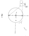
- Figure 1 is a schematic plan view of an apparatus 10 of the present invention.
- Apparatus 10 includes four single-component accelerometers 12 , 14 , 16 and 16' for measuring acceleration in the directions of the three axes of the body coordinate system. These three axes are shown in Figure 1 as an x -axis pointing upward in the plane of Figure 1, a y -axis pointing rightward in the plane of Figure 1, and a z -axis pointing downward into the plane of Figure 1.
- Accelerometer 12 is mounted rigidly with respect to the body, either within the body or on the body, to measure acceleration of the body in the body x -direction.
- Accelerometer 14 also is mounted rigidly with respect to the body, either within the body or on the body, to measure acceleration of the body in the body y -direction. Although it is not strictly necessary that the components of acceleration in the body x - y plane that are measured by accelerometers 12 and 14 be orthogonal components, it is preferable that these components be mutually orthogonal, as illustrated. Accelerometers 16 and 16' are mounted rigidly on a table 20 that rotates at a constant angular speed ⁇ around an axis of rotation 22 that is coincident with the z -axis.
- accelerometers 16 and 16' revolve about axis 22 , so that axis 22 also is an axis of revolution for accelerometers 16 and 16' .
- Accelerometers 16 and 16' are mounted at a radial distance R from axis 22 .
- Accelerometers 16 and 16' measure acceleration in the body z -direction.
- Signals from accelerometers 12 , 14 , 16 and 16' are conveyed by conventional data links, represented by dashed lines in Figure 1, to a conventional microprocessor-based data processing system 18 .
- Data processing system 18 uses the algorithms presented below to infer the Euler angles from these signals.
- Figure 2 is a partial schematic side view of apparatus 10 .
- the body x -axis points to the right
- the body y -axis points upward out of the plane of the Figure
- the body z -axis points downwards in the plane of the Figure.
- accelerometers 16 and 16' are shown mounted rigidly on table 20 , on opposite sides of axis 22 .
- Table 20 rotates about axis 22 above a platform 24 that is fixedly mounted within the body.
- a light source 26 such as a LED.
- a photodetector 28 On the surface of platform 24 that faces table 20 , at distance R from axis 22 in the positive x -direction, is a photodetector 28 . Signals from photodetector 28 are conveyed to data processing system 18 by a conventional data link represented in Figure 2 by a dashed line. Thus, every time accelerometer 16 and LED 26 pass photodetector 28 , a synchronization signal is sent to data processing system 18 .
- the mechanism for rotating table 20 at a constant angular speed is conventional and need not be elaborated here. Suffice it to say that the synchronization signal is used both to control the angular speed of table 20 and to infer the angular positions, as functions of time, of accelerometers 16 and 16' .
- accelerometers 12 and 14 are not needed.
- the Earth's angular rotation vector has only two non-zero components: an x (north) component ⁇ LN and a z (down) component ⁇ LD .
- the table coordinate system rotates with respect to the body coordinate system, about the coincident z -axes of the two coordinate systems, at an angular speed ⁇ .
- the table coordinate system is fixed in table 20 and rotates with table 20 .
- the position vector r ⁇ of accelerometer 16 is a constant:
- the transformation from LLLN coordinates to table coordinates is effected by multiplying a vector represented in LLLN coordinates by a direction cosine matrix. Specifically, let x L , y L and z L be x , y and z coordinates, respectively, in the LLLN coordinate system and let x T , y T and z T be x , y and z coordinates, respectively, in the table coordinate system. Then: where C L / T is the appropriate direction cosine matrix. With zero pitch ⁇ and zero roll ⁇ , C L / T is a function only of azimuth ⁇ , time t and angular speed ⁇ :
- ⁇ ⁇ L represent the angular velocity vector of the Earth in LLLN coordinates
- ⁇ ⁇ is a vector of magnitude ⁇ pointing in the body (or table) z -direction.
- the time derivative of ⁇ comes exclusively from the time derivative of C L / T :
- the only non-zero component of F ⁇ is the z -component of F ⁇ , which is equal to the acceleration due to gravity, g .
Landscapes
- Life Sciences & Earth Sciences (AREA)
- Environmental & Geological Engineering (AREA)
- General Life Sciences & Earth Sciences (AREA)
- Geology (AREA)
- Physics & Mathematics (AREA)
- Engineering & Computer Science (AREA)
- General Physics & Mathematics (AREA)
- Radar, Positioning & Navigation (AREA)
- Remote Sensing (AREA)
- Navigation (AREA)
- Length Measuring Devices With Unspecified Measuring Means (AREA)
Abstract
Description








Claims (25)
- A method of determining an orientation of a body, comprising the steps of:(a) measuring an acceleration of the body in a first direction;(b) measuring an acceleration of the body in a second direction different from said first direction, said first direction and said second direction defining a plane;(c) measuring an acceleration perpendicular to said plane in a coordinate system rotating about an axis perpendicular to said plane; and(d) inferring the orientation of the body from said three measurements.
- The method of claim 1, wherein said first and second directions are mutually perpendicular.
- The method of claim 1, wherein said measuring of said acceleration in said first and second directions is effected using two accelerometers mounted rigidly with respect to the body.
- The method of claim 1, wherein said rotating coordinate system rotates at a uniform angular speed with respect to the body.
- The method of claim 1, wherein said measuring of said acceleration in said rotating coordinate system is effected by steps including:(i) mounting a first accelerometer at a fixed distance from said axis; and(ii) revolving said first accelerometer about said axis.
- The method of claim 5, wherein said measuring of said acceleration in said rotating coordinate system is effected by steps further including:(iii) mounting a second accelerometer at said fixed distance from said axis; and(iv) revolving said second accelerometer about said axis along with said first accelerometer.
- The method of claim 6, wherein said first and second accelerometers are mounted on opposite sides of said axis.
- The method of claim 1, wherein said measuring of said acceleration in said rotating coordinate system is effected at a plurality of times.
- The method of claim 8, wherein said inferring is based on a phase of a time-dependent component of said acceleration in said rotating coordinate system.
- A method of determining an azimuth of a body, the azimuth being defined in a certain plane, the method comprising the steps of:(a) measuring an acceleration, perpendicular to the plane, in a coordinate system rotating about an axis perpendicular to the plane; and(b) inferring the orientation of the body from said measured acceleration.
- The method of claim 10, wherein said rotating coordinate system rotates at a uniform angular speed with respect to the body.
- The method of claim 10, wherein said measuring of said acceleration is effected by steps including:(i) mounting a first accelerometer at a fixed distance from said axis; and(ii) revolving said first accelerometer about said axis.
- The method of claim 12, wherein said measuring of said acceleration is effected by steps further including:(iii) mounting a second accelerometer at said fixed distance from said axis; and(iv) revolving said second accelerometer about said axis along with said first accelerometer.
- The method of claim 13, wherein said first and second accelerometers are mounted on opposite sides of said axis.
- The method of claim 10, wherein said measuring of said acceleration is effected at a plurality of times.
- The method of claim 15, wherein said inferring is based on a phase of a time-dependent component of said acceleration.
- An apparatus for determining an orientation of a body, comprising:(a) a first accelerometer, fixedly mounted with respect to the body, for measuring an acceleration of the body in a first direction;(b) a second accelerometer, fixedly mounted with respect to the body, for measuring an acceleration of the body in a second direction, said first and second directions defining a plane;(c) a third accelerometer for measuring an acceleration in a direction perpendicular to said plane; and(d) a mechanism for revolving said third accelerometer about an axis of revolution perpendicular to said plane.
- The apparatus of claim 17, wherein said first and second directions are mutually perpendicular.
- The apparatus of claim 17, further comprising:(e) a computational mechanism for receiving signals from said accelerometers and inferring the orientation from said signals.
- The apparatus of claim 17, further comprising:(e) a fourth accelerometer for measuring an acceleration in said direction perpendicular to said plane, said mechanism revolving both said third accelerometer and said fourth accelerometer together about said axis.
- The apparatus of claim 20, wherein said third and fourth accelerometers are mounted on said mechanism on opposite sides of said axis.
- An apparatus for determining an azimuth of a body, the azimuth being defined in a certain plane, comprising:(a) a first accelerometer, for measuring an acceleration perpendicular to the plane; and(b) a mechanism for revolving said first accelerometer about an axis of revolution perpendicular to the plane.
- The apparatus of claim 22, further comprising:(c) a computational mechanism for receiving signals from said accelerometer and inferring the azimuth from said signals.
- The apparatus of claim 22, further comprising:(c) a second accelerometer for measuring an acceleration in said direction perpendicular to the plane, said mechanism revolving both said third accelerometer and said fourth accelerometer together about said axis of revolution.
- The apparatus of claim 24, wherein said first and second accelerometers are mounted on said mechanism on opposite sides of said axis.
Applications Claiming Priority (2)
| Application Number | Priority Date | Filing Date | Title |
|---|---|---|---|
| IL12965499A IL129654A (en) | 1999-04-28 | 1999-04-28 | Method and apparatus for determining the geographical heading of a body |
| IL12965499 | 1999-04-28 |
Publications (2)
| Publication Number | Publication Date |
|---|---|
| EP1048929A2 true EP1048929A2 (en) | 2000-11-02 |
| EP1048929A3 EP1048929A3 (en) | 2003-03-19 |
Family
ID=11072740
Family Applications (1)
| Application Number | Title | Priority Date | Filing Date |
|---|---|---|---|
| EP00201501A Withdrawn EP1048929A3 (en) | 1999-04-28 | 2000-04-26 | Method and apparatus for determining the geographic heading of a body |
Country Status (4)
| Country | Link |
|---|---|
| US (1) | US6502055B1 (en) |
| EP (1) | EP1048929A3 (en) |
| AU (1) | AU2886500A (en) |
| IL (1) | IL129654A (en) |
Cited By (5)
| Publication number | Priority date | Publication date | Assignee | Title |
|---|---|---|---|---|
| WO2007015996A3 (en) * | 2005-07-26 | 2007-05-31 | Honeywell Int Inc | Apparatus and appertaining method for upfinding in spinning projectiles using a phase-lock-loop or correlator mechanism |
| EP2587216A3 (en) * | 2011-10-27 | 2013-12-18 | Thales Holdings UK Plc | Compass |
| US9091541B2 (en) | 2011-10-27 | 2015-07-28 | Thales Holdings Uk Plc | Compass |
| CN105091878A (en) * | 2014-04-23 | 2015-11-25 | 阿里巴巴集团控股有限公司 | Positioning method based on gait and positioning apparatus based on gait |
| EP2645058A3 (en) * | 2005-08-03 | 2016-07-13 | Halliburton Energy Services, Inc. | An orientation sensing apparatus and a method for determining an orientation |
Families Citing this family (5)
| Publication number | Priority date | Publication date | Assignee | Title |
|---|---|---|---|---|
| IL209261A0 (en) | 2010-11-11 | 2011-01-31 | Israel Aerospace Ind Ltd | A system and method for north finding |
| CN103298724B (en) * | 2011-01-13 | 2016-03-30 | 奥的斯电梯公司 | Apparatus and method for determining location using accelerometers |
| US9020776B2 (en) | 2011-09-28 | 2015-04-28 | Caterpillar Inc. | Inclination angle compensation systems and methods |
| US9145144B2 (en) | 2011-09-28 | 2015-09-29 | Caterpillar Inc. | Inclination detection systems and methods |
| RU2578049C1 (en) * | 2014-12-03 | 2016-03-20 | федеральное государственное автономное образовательное учреждение высшего профессионального образования "Московский физико-технический институт (государственный университет) | Method of determining direction of geographic north using molecular-electronic angular speed sensor and inclination angle sensor |
Family Cites Families (7)
| Publication number | Priority date | Publication date | Assignee | Title |
|---|---|---|---|---|
| US4445376A (en) * | 1982-03-12 | 1984-05-01 | Technion Research And Development Foundation Ltd. | Apparatus and method for measuring specific force and angular rate |
| AU1839583A (en) * | 1982-09-08 | 1984-03-15 | Commonwealth Of Australia, The | Signal processing to correct gyro compass output |
| US5369889A (en) * | 1986-07-07 | 1994-12-06 | Honeywell Inc. | Single gyro northfinder |
| US4841773A (en) * | 1987-05-01 | 1989-06-27 | Litton Systems, Inc. | Miniature inertial measurement unit |
| DE4223349A1 (en) * | 1992-07-16 | 1994-01-20 | Bosch Gmbh Robert | Angular speed sensor e.g. for vehicle - has sensors of partial silicon structure, arranged on rotating plate, for measuring forces occurring in two further orthogonal axes |
| DE19519488B4 (en) * | 1995-05-27 | 2005-03-10 | Bosch Gmbh Robert | Rate of rotation sensor with two acceleration sensors |
| US6023664A (en) * | 1996-10-16 | 2000-02-08 | Automotive Systems Laboratory, Inc. | Vehicle crash sensing system |
-
1999
- 1999-04-28 IL IL12965499A patent/IL129654A/en not_active IP Right Cessation
-
2000
- 2000-04-14 US US09/549,600 patent/US6502055B1/en not_active Expired - Fee Related
- 2000-04-18 AU AU28865/00A patent/AU2886500A/en not_active Abandoned
- 2000-04-26 EP EP00201501A patent/EP1048929A3/en not_active Withdrawn
Cited By (7)
| Publication number | Priority date | Publication date | Assignee | Title |
|---|---|---|---|---|
| WO2007015996A3 (en) * | 2005-07-26 | 2007-05-31 | Honeywell Int Inc | Apparatus and appertaining method for upfinding in spinning projectiles using a phase-lock-loop or correlator mechanism |
| US7395987B2 (en) | 2005-07-26 | 2008-07-08 | Honeywell International Inc. | Apparatus and appertaining method for upfinding in spinning projectiles using a phase-lock-loop or correlator mechanism |
| EP2645058A3 (en) * | 2005-08-03 | 2016-07-13 | Halliburton Energy Services, Inc. | An orientation sensing apparatus and a method for determining an orientation |
| EP2645057A3 (en) * | 2005-08-03 | 2016-07-13 | Halliburton Energy Services, Inc. | An orientation sensing apparatus and a method for determining an orientation |
| EP2587216A3 (en) * | 2011-10-27 | 2013-12-18 | Thales Holdings UK Plc | Compass |
| US9091541B2 (en) | 2011-10-27 | 2015-07-28 | Thales Holdings Uk Plc | Compass |
| CN105091878A (en) * | 2014-04-23 | 2015-11-25 | 阿里巴巴集团控股有限公司 | Positioning method based on gait and positioning apparatus based on gait |
Also Published As
| Publication number | Publication date |
|---|---|
| EP1048929A3 (en) | 2003-03-19 |
| US6502055B1 (en) | 2002-12-31 |
| IL129654A0 (en) | 2001-01-28 |
| IL129654A (en) | 2003-10-31 |
| AU2886500A (en) | 2000-11-09 |
Similar Documents
| Publication | Publication Date | Title |
|---|---|---|
| US6459990B1 (en) | Self-contained positioning method and system thereof for water and land vehicles | |
| US7346452B2 (en) | Inertial GPS navigation system using injected alignment data for the inertial system | |
| US7162367B2 (en) | Self-contained/interruption-free positioning method and system thereof | |
| US6415223B1 (en) | Interruption-free hand-held positioning method and system thereof | |
| US6658354B2 (en) | Interruption free navigator | |
| US6879875B1 (en) | Low cost multisensor high precision positioning and data integrated method and system thereof | |
| EP2026036B1 (en) | Gyroscope north seeker system and method | |
| EP0870175B1 (en) | A zero motion detection system for improved vehicle navigation system | |
| US20060287824A1 (en) | Interruption free navigator | |
| EP2583059B1 (en) | Improved north finder | |
| US20020173910A1 (en) | Vehicle self-carried positioning method and system thereof | |
| KR101765318B1 (en) | System and method for measurement of angular orientation of aerospace platforms | |
| JP2000502802A (en) | Improved vehicle navigation system and method utilizing GPS speed | |
| JP6339429B2 (en) | Device and method for determining orientation | |
| JP2000506604A (en) | Improved vehicle navigation system and method | |
| JP4316777B2 (en) | Gravity measuring device and method | |
| Hein | An integrated low cost GPS/INS attitude determination and position location system | |
| US3414899A (en) | Apparatus for calibrating doppler-inertial navigation systems | |
| EP3748294B1 (en) | Direction finder | |
| US6502055B1 (en) | Method and apparatus for determining the geographic heading of a body | |
| RU2256881C2 (en) | Method of estimation of orientation and navigation parameters and strap-down inertial navigation system for fast rotating objects | |
| IL278733B1 (en) | Method for harmonizing two inertial measurement units with each other and navigation system implementing this method | |
| US5042156A (en) | Method and apparatus for reducing measurement errors in a navigation triad | |
| Mandapat | Development and evaluation of positioning systems for autonomous vehicle navigation | |
| Stanisak | Inertial Technology: Sensors, Algorithms, and Integration |
Legal Events
| Date | Code | Title | Description |
|---|---|---|---|
| PUAI | Public reference made under article 153(3) epc to a published international application that has entered the european phase |
Free format text: ORIGINAL CODE: 0009012 |
|
| AK | Designated contracting states |
Kind code of ref document: A2 Designated state(s): AT BE CH CY DE DK ES FI FR GB GR IE IT LI LU MC NL PT SE |
|
| AX | Request for extension of the european patent |
Free format text: AL;LT;LV;MK;RO;SI |
|
| RAP1 | Party data changed (applicant data changed or rights of an application transferred) |
Owner name: RAFAEL ARMAMENT DEVELOPMENT AUTHORITY LTD. |
|
| PUAL | Search report despatched |
Free format text: ORIGINAL CODE: 0009013 |
|
| AK | Designated contracting states |
Kind code of ref document: A3 Designated state(s): AT BE CH CY DE DK ES FI FR GB GR IE IT LI LU MC NL PT SE Designated state(s): AT BE CH CY DE DK ES FI FR GB GR IE IT LI LU MC NL PT SE |
|
| AX | Request for extension of the european patent |
Extension state: AL LT LV MK RO SI |
|
| RIC1 | Information provided on ipc code assigned before grant |
Ipc: 7G 01C 21/10 B Ipc: 7G 01C 19/34 B Ipc: 7G 01C 19/56 A |
|
| AKX | Designation fees paid | ||
| REG | Reference to a national code |
Ref country code: DE Ref legal event code: 8566 |
|
| STAA | Information on the status of an ep patent application or granted ep patent |
Free format text: STATUS: THE APPLICATION IS DEEMED TO BE WITHDRAWN |
|
| 18D | Application deemed to be withdrawn |
Effective date: 20030502 |