EP1048874A1 - A disk for a disk brake - Google Patents
A disk for a disk brake Download PDFInfo
- Publication number
- EP1048874A1 EP1048874A1 EP99830252A EP99830252A EP1048874A1 EP 1048874 A1 EP1048874 A1 EP 1048874A1 EP 99830252 A EP99830252 A EP 99830252A EP 99830252 A EP99830252 A EP 99830252A EP 1048874 A1 EP1048874 A1 EP 1048874A1
- Authority
- EP
- European Patent Office
- Prior art keywords
- disk
- recess
- braking
- braking band
- band
- Prior art date
- Legal status (The legal status is an assumption and is not a legal conclusion. Google has not performed a legal analysis and makes no representation as to the accuracy of the status listed.)
- Granted
Links
- 238000009423 ventilation Methods 0.000 claims description 4
- 125000006850 spacer group Chemical group 0.000 claims description 3
- 239000007787 solid Substances 0.000 description 3
- 238000007792 addition Methods 0.000 description 1
- 230000005284 excitation Effects 0.000 description 1
- 230000002035 prolonged effect Effects 0.000 description 1
- 238000009877 rendering Methods 0.000 description 1
Images


Classifications
-
- F—MECHANICAL ENGINEERING; LIGHTING; HEATING; WEAPONS; BLASTING
- F16—ENGINEERING ELEMENTS AND UNITS; GENERAL MEASURES FOR PRODUCING AND MAINTAINING EFFECTIVE FUNCTIONING OF MACHINES OR INSTALLATIONS; THERMAL INSULATION IN GENERAL
- F16D—COUPLINGS FOR TRANSMITTING ROTATION; CLUTCHES; BRAKES
- F16D65/00—Parts or details
- F16D65/02—Braking members; Mounting thereof
- F16D65/12—Discs; Drums for disc brakes
- F16D65/128—Discs; Drums for disc brakes characterised by means for cooling
-
- F—MECHANICAL ENGINEERING; LIGHTING; HEATING; WEAPONS; BLASTING
- F16—ENGINEERING ELEMENTS AND UNITS; GENERAL MEASURES FOR PRODUCING AND MAINTAINING EFFECTIVE FUNCTIONING OF MACHINES OR INSTALLATIONS; THERMAL INSULATION IN GENERAL
- F16D—COUPLINGS FOR TRANSMITTING ROTATION; CLUTCHES; BRAKES
- F16D65/00—Parts or details
- F16D65/0006—Noise or vibration control
-
- F—MECHANICAL ENGINEERING; LIGHTING; HEATING; WEAPONS; BLASTING
- F16—ENGINEERING ELEMENTS AND UNITS; GENERAL MEASURES FOR PRODUCING AND MAINTAINING EFFECTIVE FUNCTIONING OF MACHINES OR INSTALLATIONS; THERMAL INSULATION IN GENERAL
- F16D—COUPLINGS FOR TRANSMITTING ROTATION; CLUTCHES; BRAKES
- F16D65/00—Parts or details
- F16D65/02—Braking members; Mounting thereof
- F16D65/12—Discs; Drums for disc brakes
- F16D65/127—Discs; Drums for disc brakes characterised by properties of the disc surface; Discs lined with friction material
-
- F—MECHANICAL ENGINEERING; LIGHTING; HEATING; WEAPONS; BLASTING
- F16—ENGINEERING ELEMENTS AND UNITS; GENERAL MEASURES FOR PRODUCING AND MAINTAINING EFFECTIVE FUNCTIONING OF MACHINES OR INSTALLATIONS; THERMAL INSULATION IN GENERAL
- F16D—COUPLINGS FOR TRANSMITTING ROTATION; CLUTCHES; BRAKES
- F16D65/00—Parts or details
- F16D65/02—Braking members; Mounting thereof
- F16D2065/13—Parts or details of discs or drums
- F16D2065/1304—Structure
- F16D2065/1308—Structure one-part
-
- F—MECHANICAL ENGINEERING; LIGHTING; HEATING; WEAPONS; BLASTING
- F16—ENGINEERING ELEMENTS AND UNITS; GENERAL MEASURES FOR PRODUCING AND MAINTAINING EFFECTIVE FUNCTIONING OF MACHINES OR INSTALLATIONS; THERMAL INSULATION IN GENERAL
- F16D—COUPLINGS FOR TRANSMITTING ROTATION; CLUTCHES; BRAKES
- F16D65/00—Parts or details
- F16D65/02—Braking members; Mounting thereof
- F16D2065/13—Parts or details of discs or drums
- F16D2065/1304—Structure
- F16D2065/1328—Structure internal cavities, e.g. cooling channels
-
- F—MECHANICAL ENGINEERING; LIGHTING; HEATING; WEAPONS; BLASTING
- F16—ENGINEERING ELEMENTS AND UNITS; GENERAL MEASURES FOR PRODUCING AND MAINTAINING EFFECTIVE FUNCTIONING OF MACHINES OR INSTALLATIONS; THERMAL INSULATION IN GENERAL
- F16D—COUPLINGS FOR TRANSMITTING ROTATION; CLUTCHES; BRAKES
- F16D69/00—Friction linings; Attachment thereof; Selection of coacting friction substances or surfaces
- F16D2069/004—Profiled friction surfaces, e.g. grooves, dimples
Definitions
- the subject of the present invention is a disk for a disk brake.
- a disk-brake disk of known type comprises, basically, a support bell for connection, for example, to the wheel hub of a vehicle.
- the braking band is fixed to the bell by means of a connecting projection and cooperates with callipers to perform the braking action on the vehicle.
- the object of the present invention is to propose a disk for a disk brake of the type specified above, which has structural and functional characteristics such as to overcome the problems mentioned above in relation to the prior art.
- a disk of the type specified which is characterized in that at least one braking surface of the braking band has at least one recess or groove which extends along a circle concentric with the axis of symmetry of the disk.
- a disk-brake disk is generally indicated 10.
- the disk extends around an axis of symmetry, indicated (s).
- a bell 12 In the centre of the disk 10 there is a bell 12.
- the bell can be coupled, for example, to a hub of a vehicle, by means of a bearing surface 13.
- a braking band 18 is supported by the bell 12 by means of a connecting projection 16.
- At least one braking surface 20 of the braking band 18 advantageously has at least one recess 22 extending along a circle, indicated by a chain line 24.
- the circle 24 is arranged concentrically relative to the axis of symmetry (s) of the disk 10.
- the recess 22 is annular, that is, it extends around a closed circle.
- the braking surface of the band is interrupted by virtue of the presence of the recess 22.
- Two channels or grooves 26 and 28 may advantageously be provided in the braking band 18 of the disk 10.
- the channels 26, 28 are formed in the inner and outer braking surfaces 20 and 30 of the disk 10.
- the channels extend along circles 24 and 32 concentric with the axis of symmetry (s) of the disk.
- the circles 24 and 32 are preferably disposed the same distance 34 from the axis (s).
- the circle 24, 32 along which the recess 22 or the channels 26, 28 extend interrupts the braking surface 20, 30 in a position disposed from 1/4 to 4/5 of the band 18 width 100 and, preferably, at 3/5 or 1/2 of the band 18 width 100.
- the braking band 18 is constituted by two rings 36 and 38 connected to one another by means of a bridge 40.
- the recess provided in the braking surface constitutes a localized region of structural flexibility of the band 18 which permits unusually quiet braking.
- the emission of sound waves generated by the disk when it is stressed by a braking action is reduced.
- the recess modifies the dynamic flexibility of the disk locally and the disk consequently adopts vibration modes with different frequencies in comparison with a disk of the same geometrical shape and mass but without the recess.
- the vibration modes are advantageously outside the frequency range usually excited during braking. Since the frequencies excited to the greatest extent during braking are within limited frequency ranges or intervals, by virtue of the provision of at least one recess in the braking surfaces of the disk, extending along a circle concentric with the axis of the disk, the frequencies of the principal vibration modes of the disk are outside the frequency ranges excited, rendering the disk unusually quiet.
- the disk 10 is advantageously self-ventilated.
- the braking band 18 of the disk 10 comprises an outer plate 42 and an inner plate 44 disposed facing one another so as to form a space 46 for the outflow of air.
- the inner plate 44 is fixed to the outer plate 42 by spacers, for example, fins 48 shaped so as to define ventilation ducts.
- At least one of the plates 42, 44 of the braking band 18 has a recess 50 which extends along a circle concentric with the axis of symmetry (s) of the disk 10.
- the braking band 18 of a self-ventilated disk 10 has, in its surfaces 20, 30, lateral recesses 52, 54 of a depth equal to the thickness of the plates 42, 44.
- the recesses 52, 54 communicate with the ventilation ducts of the space 46, forming routes for the outflow of air laterally relative to the disk 10.
- the recesses 52, 54 divide the plates 42, 44 into two concentric rings, indicated 56 and 58 and 60, 62, respectively.
- the braking band 18 is advantageously reinforced by the provision of connecting spacers, for example, small pillars 48 or pins, between the plates 42, 44.
- the pillars 48 interconnect the rings 56, 58, 60, 62 in the region of the space 46 and, by means of lateral extensions 64 which partially penetrate the recesses 52, 54, also in the region of the walls of the recesses 52, 54.
- This vibration of the disk 10 takes place in accordance with the disk's own modes of vibration which are modified, in comparison with a continuous band, by the presence of the recesses 22, 26 and 28 disposed along circles 24, 32.
- the band 18 is in fact broken up by the recesses into concentric rings 36, 38, 56, 58 and 60, 62.
- the action of the pads will, above all, drive vibrations in certain frequency ranges which are not significant vibration modes of the disk.
- These vibration modes of the disk 10, which are excited little or not at all, will emit sound waves 35 of low amplitude.
- only one recess 22 may be provided disposed, for example, on the outer side 30 of the braking band 18 ( Figure 6).
- this embodiment also prevents the braking band from being deformed excessively towards the inner side 20 of the disk 10 in the event of large increases in temperature.
- Figure 7 shows a self-ventilated disk 10 having a circular recess 54.
- the disk 10 has its inner plate 44 fixed to its outer plate by means of small pillars 66, commonly known as pins.
- Figure 8 shows a self-ventilated disk 10 having channels 68, 70 extending in the thickness of the plates 42, 44.
- the channels 68, 70 interrupt the braking band 18 forming, on each plate 42, 44, concentric rings 56, 58 and 60, 62 which vibrate during an excitation induced by the pads, emitting sound waves of low amplitude.
- a self-ventilated brake disk 10 has, in its plates 42, 44, recesses 72, 74 which extend along a circle concentric with the axis of symmetry (s).
- the recesses 72, 74 have a cross-section which diverges from the inner side to the outer side of the braking band 18.
- the cross-section of the recesses 72, 74 has a shaped profile. This particular shape of the cross-section of the recess favours a lateral outflow of air from the disk 10 as well as reducing the amplitude of the sound waves emitted by the disk 10.
- Figure 10 shows a further embodiment of the invention.
- a plurality of slots 76 advantageously extend along a circle concentric with the axis of symmetry (s) of the disk 10.
- the slots 76 are spaced apart uniformly so as not to unbalance the disk 10 during its rotation. This embodiment is particularly advantageous if the disk 10 has to be used for particularly heavy braking of a vehicle such as, for example, prolonged braking and braking from high speeds.
Landscapes
- Engineering & Computer Science (AREA)
- General Engineering & Computer Science (AREA)
- Mechanical Engineering (AREA)
- Braking Arrangements (AREA)
Abstract
Description
- The subject of the present invention is a disk for a disk brake.
- A disk-brake disk of known type comprises, basically, a support bell for connection, for example, to the wheel hub of a vehicle. The braking band is fixed to the bell by means of a connecting projection and cooperates with callipers to perform the braking action on the vehicle.
- As is known, these disks are subject to vibrations which translate into annoying whistling.
- The object of the present invention is to propose a disk for a disk brake of the type specified above, which has structural and functional characteristics such as to overcome the problems mentioned above in relation to the prior art.
- This object is achieved by a disk of the type specified, which is characterized in that at least one braking surface of the braking band has at least one recess or groove which extends along a circle concentric with the axis of symmetry of the disk.
- For a better understanding of the invention, a non-limiting embodiment thereof is described below and illustrated in the appended drawings, in which:
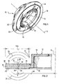
- Figure 1 is an axonometric view of a solid disk,
- Figure 2 is a cross-section of the disk of Figure 1,
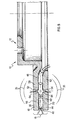
- Figure 3 is an axonometric view of a self-ventilated disk,
- Figure 4 is a side view of a detail of the disk of Figure 3,
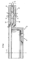
- Figure 5 shows a detail of a cross-section of a self-ventilated disk,
- Figure 6 shows a second embodiment of a solid brake disk, in section,
- Figure 7 is a side view of a detail of a braking band of a self-ventilated disk of a third embodiment,
- Figures 8 and 9 show, in cross-section, a detail of a self-ventilated disk according to a fourth and a fifth embodiment, and
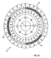
- Figure 10 is a side view of a self-ventilated disk in a further embodiment of the invention.
-
- With reference to Figure 1, a disk-brake disk is generally indicated 10. The disk extends around an axis of symmetry, indicated (s). In the centre of the
disk 10 there is abell 12. The bell can be coupled, for example, to a hub of a vehicle, by means of abearing surface 13. Abraking band 18 is supported by thebell 12 by means of a connectingprojection 16. - At least one
braking surface 20 of thebraking band 18 advantageously has at least onerecess 22 extending along a circle, indicated by achain line 24. Thecircle 24 is arranged concentrically relative to the axis of symmetry (s) of thedisk 10. - With further advantage, the
recess 22 is annular, that is, it extends around a closed circle. - The braking surface of the band is interrupted by virtue of the presence of the
recess 22. - Two channels or
grooves 26 and 28 (Figure 2) may advantageously be provided in thebraking band 18 of thedisk 10. Thechannels outer braking surfaces disk 10. The channels extend alongcircles circles same distance 34 from the axis (s). - With further advantage, the
circle channels braking surface band 18width 100 and, preferably, at 3/5 or 1/2 of theband 18width 100. - The provision of the
channels surfaces disk 10 which participate to the greatest extent in emittingsound waves 35. In particular, by virtue of the provision of therecess 22 or of thechannels circles disk 10, thebraking band 18 is constituted by tworings bridge 40. - The recess provided in the braking surface constitutes a localized region of structural flexibility of the
band 18 which permits unusually quiet braking. In particular, with the disk proposed, the emission of sound waves generated by the disk when it is stressed by a braking action is reduced. - In other words, the recess modifies the dynamic flexibility of the disk locally and the disk consequently adopts vibration modes with different frequencies in comparison with a disk of the same geometrical shape and mass but without the recess. The vibration modes are advantageously outside the frequency range usually excited during braking. Since the frequencies excited to the greatest extent during braking are within limited frequency ranges or intervals, by virtue of the provision of at least one recess in the braking surfaces of the disk, extending along a circle concentric with the axis of the disk, the frequencies of the principal vibration modes of the disk are outside the frequency ranges excited, rendering the disk unusually quiet.
- As can be seen from Figures 3 and 4, the
disk 10 is advantageously self-ventilated. In this embodiment, thebraking band 18 of thedisk 10 comprises anouter plate 42 and aninner plate 44 disposed facing one another so as to form aspace 46 for the outflow of air. Theinner plate 44 is fixed to theouter plate 42 by spacers, for example,fins 48 shaped so as to define ventilation ducts. - Advantageously, at least one of the
plates braking band 18 has arecess 50 which extends along a circle concentric with the axis of symmetry (s) of thedisk 10. - An advantageous embodiment of the invention can be seen in Figure 5. The
braking band 18 of a self-ventilateddisk 10 has, in itssurfaces lateral recesses plates recesses space 46, forming routes for the outflow of air laterally relative to thedisk 10. Therecesses plates - The
braking band 18 is advantageously reinforced by the provision of connecting spacers, for example,small pillars 48 or pins, between theplates pillars 48 interconnect therings space 46 and, by means oflateral extensions 64 which partially penetrate therecesses recesses - The operation of the
disk 10 is described below with reference to Figures 2 and 5. - During braking, a vibration is induced in the
disk 10 because of the action of the pads on thesurfaces braking band 18. - This vibration of the
disk 10 takes place in accordance with the disk's own modes of vibration which are modified, in comparison with a continuous band, by the presence of therecesses circles band 18 is in fact broken up by the recesses intoconcentric rings - In particular, the action of the pads will, above all, drive vibrations in certain frequency ranges which are not significant vibration modes of the disk. These vibration modes of the
disk 10, which are excited little or not at all, will emitsound waves 35 of low amplitude. - Clearly, variations and/or additions may be applied to the embodiments described above.
- In the case of a
solid disk 10, only onerecess 22 may be provided disposed, for example, on theouter side 30 of the braking band 18 (Figure 6). As well as dividing thebraking band 18 into twoconcentric rings inner side 20 of thedisk 10 in the event of large increases in temperature. - Naturally it will be necessary to provide for the use of pads which are unloaded in the region of the recess on both braking surfaces, even in the absence of a recess, so as to level out the wear of the pads.
- Figure 7 shows a self-ventilated
disk 10 having acircular recess 54. Thedisk 10 has itsinner plate 44 fixed to its outer plate by means ofsmall pillars 66, commonly known as pins. - Figure 8 shows a self-ventilated
disk 10 havingchannels plates channels braking band 18 forming, on eachplate concentric rings - As can be seen from Figure 9, a self-ventilated
brake disk 10 has, in itsplates recesses recesses braking band 18. With further advantage, the cross-section of therecesses disk 10 as well as reducing the amplitude of the sound waves emitted by thedisk 10. - Figure 10 shows a further embodiment of the invention. A plurality of
slots 76 advantageously extend along a circle concentric with the axis of symmetry (s) of thedisk 10. Theslots 76 are spaced apart uniformly so as not to unbalance thedisk 10 during its rotation. This embodiment is particularly advantageous if thedisk 10 has to be used for particularly heavy braking of a vehicle such as, for example, prolonged braking and braking from high speeds.
Claims (12)
- A disk (10) for a disk brake, comprising a braking band (18), characterized in that at least one braking surface (20, 30) of the braking band (18) has at least one recess (22, 26, 28, 50, 52, 54, 68, 70, 72, 74, 76) which extends along a circle (24, 32) concentric with the axis of symmetry (s) of the disk (10).
- A disk (10) according to Claim 1, in which the recess (22, 26, 28, 50, 52, 54, 68, 70, 72, 74) is annular.
- A disk (10) according to Claim 1 or Claim 2, in which the braking band (18) is self-ventilated and at least one plate (42, 44) of the braking band (18) has the recess (50, 52, 54, 68, 70, 72, 74, 76).
- A disk (10) according to Claim 3, further comprising a ventilation duct of the braking band (18), the ventilation duct being delimited by spacers, and in which the recess (52, 54, 72, 74) has a depth equal to the thickness of the plate (42, 44).
- A disk (10) according to Claim 3 or Claim 4, in which the recess (50, 52, 54, 68, 70, 72, 74, 76) is provided in all of the plates (42, 44).
- A disk (10) according to Claim 1, in which the recess (72, 74) has a cross-section which diverges from the inner side of the braking band (18) to its outer side.
- A disk (10) according to Claim 1, in which the recess (22, 26, 28, 50, 52, 54, 68, 70, 72, 74, 76) interrupts the braking band (18) in a position variable from 1/4 to 4/5 of the braking band (18) width (100).
- A disk (10) according to Claim 7, in which the recess (22, 26, 28, 50, 52, 54, 68, 70, 72, 74, 76) is provided at 3/5 of the braking band (18) width (100).
- A disk (10) according to Claim 7, in which the recess 22, 26, 28, 50, 52, 54, 68, 70, 72, 74, 76) is provided at 1/2 of the braking band (18) width (100).
- A disk (10) according to any one of the preceding claims, in which the recess (76) is a slot.
- A disk (10) according to Claim 1, in which the braking band (18) has a plurality of slots (76) which extend along a circle symmetrically with respect to the axis (s) of the disk (10).
- A disk (10) according to Claim 10, in which the braking band (18) has three slots (76) spaced uniformly around the circle.
Priority Applications (3)
| Application Number | Priority Date | Filing Date | Title |
|---|---|---|---|
| DE69929768T DE69929768D1 (en) | 1999-04-28 | 1999-04-28 | Disc for a disc brake |
| AT99830252T ATE317508T1 (en) | 1999-04-28 | 1999-04-28 | DISC FOR A DISC BRAKE |
| EP99830252A EP1048874B1 (en) | 1999-04-28 | 1999-04-28 | A disk for a disk brake |
Applications Claiming Priority (1)
| Application Number | Priority Date | Filing Date | Title |
|---|---|---|---|
| EP99830252A EP1048874B1 (en) | 1999-04-28 | 1999-04-28 | A disk for a disk brake |
Publications (2)
| Publication Number | Publication Date |
|---|---|
| EP1048874A1 true EP1048874A1 (en) | 2000-11-02 |
| EP1048874B1 EP1048874B1 (en) | 2006-02-08 |
Family
ID=8243378
Family Applications (1)
| Application Number | Title | Priority Date | Filing Date |
|---|---|---|---|
| EP99830252A Expired - Lifetime EP1048874B1 (en) | 1999-04-28 | 1999-04-28 | A disk for a disk brake |
Country Status (3)
| Country | Link |
|---|---|
| EP (1) | EP1048874B1 (en) |
| AT (1) | ATE317508T1 (en) |
| DE (1) | DE69929768D1 (en) |
Cited By (10)
| Publication number | Priority date | Publication date | Assignee | Title |
|---|---|---|---|---|
| WO2002097291A1 (en) * | 2001-05-28 | 2002-12-05 | Freni Brembo S.P.A. | Method and tools for the production of a braking band for a brake disk |
| WO2002097292A1 (en) * | 2001-05-28 | 2002-12-05 | Freni Brembo S.P.A. | A braking band for a brake disk |
| WO2002097293A1 (en) * | 2001-05-28 | 2002-12-05 | Freni Brembo S.P.A. | A braking band for a brake disk |
| WO2004094858A1 (en) * | 2003-04-11 | 2004-11-04 | Warren Lin | Reinforced brake rotor |
| WO2004097244A1 (en) * | 2003-04-11 | 2004-11-11 | Warren Lin | Vented slot brake rotor |
| WO2006067816A1 (en) * | 2004-12-24 | 2006-06-29 | Freni Brembo S.P.A. | Braking band of disc brake |
| WO2007091282A1 (en) * | 2006-02-07 | 2007-08-16 | Freni Brembo S.P.A. | Brake disc |
| US8851245B2 (en) | 2010-12-03 | 2014-10-07 | Brake Parts Inc Llc | Brake rotor |
| CN105805193A (en) * | 2016-04-21 | 2016-07-27 | 成都科创诺商贸有限公司 | Automobile brake disc |
| DE102023102974A1 (en) * | 2023-02-07 | 2024-08-08 | Hl Mando Corporation | CALIPER BRAKE |
Citations (10)
| Publication number | Priority date | Publication date | Assignee | Title |
|---|---|---|---|---|
| US2368621A (en) * | 1942-12-30 | 1945-02-06 | American Steel Foundries | Brake rotor |
| FR1535705A (en) * | 1967-06-29 | 1968-08-09 | Messier Fa | Brake disc improvements |
| DE2217009A1 (en) * | 1972-04-08 | 1973-10-18 | Teves Gmbh Alfred | BRAKE DISC FOR DISC BRAKES |
| DE2837634A1 (en) * | 1978-08-29 | 1980-03-06 | Teves Gmbh Alfred | Floating caliper vehicle disc brake - has circumferential groove in disc and matching projection on brake pad |
| JPS60237234A (en) * | 1984-05-10 | 1985-11-26 | Sumitomo Electric Ind Ltd | Disc rotor for disc brake |
| JPH0415328A (en) * | 1990-05-10 | 1992-01-20 | Fukushima Seiko Kk | Rotor for disk brake |
| EP0494494A1 (en) * | 1991-01-07 | 1992-07-15 | Borg-Warner Automotive Transmission And Engine Components Corporation | Energy transfer device |
| US5139117A (en) * | 1990-08-27 | 1992-08-18 | General Motors Corporation | Damped disc brake rotor |
| EP0521754A1 (en) * | 1991-07-02 | 1993-01-07 | Automobiles Peugeot | Ventilated brake disc and mold for the fabrication of this disc |
| US5238089A (en) * | 1989-12-20 | 1993-08-24 | Akebono Brake Industry Co., Ltd. | Squeak prevention for disc brake |
-
1999
- 1999-04-28 DE DE69929768T patent/DE69929768D1/en not_active Expired - Lifetime
- 1999-04-28 EP EP99830252A patent/EP1048874B1/en not_active Expired - Lifetime
- 1999-04-28 AT AT99830252T patent/ATE317508T1/en not_active IP Right Cessation
Patent Citations (10)
| Publication number | Priority date | Publication date | Assignee | Title |
|---|---|---|---|---|
| US2368621A (en) * | 1942-12-30 | 1945-02-06 | American Steel Foundries | Brake rotor |
| FR1535705A (en) * | 1967-06-29 | 1968-08-09 | Messier Fa | Brake disc improvements |
| DE2217009A1 (en) * | 1972-04-08 | 1973-10-18 | Teves Gmbh Alfred | BRAKE DISC FOR DISC BRAKES |
| DE2837634A1 (en) * | 1978-08-29 | 1980-03-06 | Teves Gmbh Alfred | Floating caliper vehicle disc brake - has circumferential groove in disc and matching projection on brake pad |
| JPS60237234A (en) * | 1984-05-10 | 1985-11-26 | Sumitomo Electric Ind Ltd | Disc rotor for disc brake |
| US5238089A (en) * | 1989-12-20 | 1993-08-24 | Akebono Brake Industry Co., Ltd. | Squeak prevention for disc brake |
| JPH0415328A (en) * | 1990-05-10 | 1992-01-20 | Fukushima Seiko Kk | Rotor for disk brake |
| US5139117A (en) * | 1990-08-27 | 1992-08-18 | General Motors Corporation | Damped disc brake rotor |
| EP0494494A1 (en) * | 1991-01-07 | 1992-07-15 | Borg-Warner Automotive Transmission And Engine Components Corporation | Energy transfer device |
| EP0521754A1 (en) * | 1991-07-02 | 1993-01-07 | Automobiles Peugeot | Ventilated brake disc and mold for the fabrication of this disc |
Non-Patent Citations (2)
| Title |
|---|
| PATENT ABSTRACTS OF JAPAN vol. 010, no. 105 (M - 471) 19 April 1986 (1986-04-19) * |
| PATENT ABSTRACTS OF JAPAN vol. 016, no. 169 (M - 1239) 23 April 1992 (1992-04-23) * |
Cited By (17)
| Publication number | Priority date | Publication date | Assignee | Title |
|---|---|---|---|---|
| US7228947B2 (en) | 2001-05-28 | 2007-06-12 | Freni Brembo S.P.A. | Method and tools for the production of a braking band for a brake disk |
| WO2002097292A1 (en) * | 2001-05-28 | 2002-12-05 | Freni Brembo S.P.A. | A braking band for a brake disk |
| WO2002097293A1 (en) * | 2001-05-28 | 2002-12-05 | Freni Brembo S.P.A. | A braking band for a brake disk |
| JP2004526923A (en) * | 2001-05-28 | 2004-09-02 | フレニ・ブレンボ エス・ピー・エー | Manufacturing method and manufacturing tool for brake band for brake disc |
| WO2002097291A1 (en) * | 2001-05-28 | 2002-12-05 | Freni Brembo S.P.A. | Method and tools for the production of a braking band for a brake disk |
| US7234572B2 (en) | 2001-05-28 | 2007-06-26 | Freni Brembo S.P.A. | Braking band for a brake disk |
| WO2004094858A1 (en) * | 2003-04-11 | 2004-11-04 | Warren Lin | Reinforced brake rotor |
| US7097007B2 (en) * | 2003-04-11 | 2006-08-29 | Warren Lin | Vented slot brake rotor |
| WO2004097244A1 (en) * | 2003-04-11 | 2004-11-11 | Warren Lin | Vented slot brake rotor |
| WO2006067816A1 (en) * | 2004-12-24 | 2006-06-29 | Freni Brembo S.P.A. | Braking band of disc brake |
| WO2007091282A1 (en) * | 2006-02-07 | 2007-08-16 | Freni Brembo S.P.A. | Brake disc |
| US7641027B2 (en) | 2006-02-07 | 2010-01-05 | Freni Brembo S.P.A. | Brake disc |
| US8851245B2 (en) | 2010-12-03 | 2014-10-07 | Brake Parts Inc Llc | Brake rotor |
| US9163683B2 (en) | 2010-12-03 | 2015-10-20 | Brake Parts Inc Llc | Brake rotor |
| CN105805193A (en) * | 2016-04-21 | 2016-07-27 | 成都科创诺商贸有限公司 | Automobile brake disc |
| DE102023102974A1 (en) * | 2023-02-07 | 2024-08-08 | Hl Mando Corporation | CALIPER BRAKE |
| DE102023102974B4 (en) * | 2023-02-07 | 2024-08-29 | Hl Mando Corporation | CALIPER BRAKE |
Also Published As
| Publication number | Publication date |
|---|---|
| ATE317508T1 (en) | 2006-02-15 |
| EP1048874B1 (en) | 2006-02-08 |
| DE69929768D1 (en) | 2006-04-20 |
Similar Documents
| Publication | Publication Date | Title |
|---|---|---|
| US5735366A (en) | Disk brake rotor exhibiting different modes of vibration on opposite sides during braking | |
| EP1416183B1 (en) | A rotor with surface having a plurality of indentations formed therein | |
| EP1048874A1 (en) | A disk for a disk brake | |
| US6347691B1 (en) | Arrangement for preventing the squealing of a disk brake | |
| US6161660A (en) | Rotor for disc brake | |
| JP4890735B2 (en) | Braking band and disc for disc brake | |
| JP2013545054A (en) | Brake rotor | |
| JP2020535357A (en) | Brake device | |
| JP2022543629A (en) | Brake band for ventilated type disc brake | |
| CN103542023B (en) | brake disc | |
| EP1384011B1 (en) | A braking band for a brake disk | |
| EP1301728B1 (en) | A disc for a disc brake | |
| JP2022543630A (en) | Brake band for ventilated type disc brake | |
| CN114641625A (en) | Braking band for disc of ventilated-type disc brake | |
| JP2002048166A (en) | Disc rotor for disc brake device for vehicles | |
| JP3136459B2 (en) | Disc rotor for vehicle disc brakes | |
| JP4095252B2 (en) | Friction pad for disc brake | |
| US20230279913A1 (en) | Disc brake arrangement having brake lining at in outer circumferential face of a brake disc | |
| JPS62297549A (en) | brake disc | |
| JPS6360252B2 (en) | ||
| CN114641624A (en) | Braking band for disc of ventilated-type disc brake | |
| KR20030088265A (en) | A curved brake disk provided with an involute type vent passage | |
| JPS58200827A (en) | Disk rotor for disk brake | |
| US20090050422A1 (en) | Grooved disc brake rotor | |
| JP7364211B2 (en) | brake rotor |
Legal Events
| Date | Code | Title | Description |
|---|---|---|---|
| PUAI | Public reference made under article 153(3) epc to a published international application that has entered the european phase |
Free format text: ORIGINAL CODE: 0009012 |
|
| AK | Designated contracting states |
Kind code of ref document: A1 Designated state(s): AT BE CH CY DE DK ES FI FR GB GR IE IT LI LU MC NL PT SE |
|
| AX | Request for extension of the european patent |
Free format text: AL;LT;LV;MK;RO;SI |
|
| 17P | Request for examination filed |
Effective date: 20010427 |
|
| AKX | Designation fees paid |
Free format text: AT BE CH CY DE DK ES FI FR GB GR IE IT LI LU MC NL PT SE |
|
| 17Q | First examination report despatched |
Effective date: 20040827 |
|
| GRAP | Despatch of communication of intention to grant a patent |
Free format text: ORIGINAL CODE: EPIDOSNIGR1 |
|
| GRAS | Grant fee paid |
Free format text: ORIGINAL CODE: EPIDOSNIGR3 |
|
| GRAA | (expected) grant |
Free format text: ORIGINAL CODE: 0009210 |
|
| RIN1 | Information on inventor provided before grant (corrected) |
Inventor name: OBERTI, LUCA Inventor name: GOTTI, GIOVANNI |
|
| AK | Designated contracting states |
Kind code of ref document: B1 Designated state(s): AT BE CH CY DE DK ES FI FR GB GR IE IT LI LU MC NL PT SE |
|
| PG25 | Lapsed in a contracting state [announced via postgrant information from national office to epo] |
Ref country code: NL Free format text: LAPSE BECAUSE OF FAILURE TO SUBMIT A TRANSLATION OF THE DESCRIPTION OR TO PAY THE FEE WITHIN THE PRESCRIBED TIME-LIMIT Effective date: 20060208 Ref country code: LI Free format text: LAPSE BECAUSE OF FAILURE TO SUBMIT A TRANSLATION OF THE DESCRIPTION OR TO PAY THE FEE WITHIN THE PRESCRIBED TIME-LIMIT Effective date: 20060208 Ref country code: FI Free format text: LAPSE BECAUSE OF FAILURE TO SUBMIT A TRANSLATION OF THE DESCRIPTION OR TO PAY THE FEE WITHIN THE PRESCRIBED TIME-LIMIT Effective date: 20060208 Ref country code: CH Free format text: LAPSE BECAUSE OF FAILURE TO SUBMIT A TRANSLATION OF THE DESCRIPTION OR TO PAY THE FEE WITHIN THE PRESCRIBED TIME-LIMIT Effective date: 20060208 Ref country code: BE Free format text: LAPSE BECAUSE OF FAILURE TO SUBMIT A TRANSLATION OF THE DESCRIPTION OR TO PAY THE FEE WITHIN THE PRESCRIBED TIME-LIMIT Effective date: 20060208 Ref country code: AT Free format text: LAPSE BECAUSE OF FAILURE TO SUBMIT A TRANSLATION OF THE DESCRIPTION OR TO PAY THE FEE WITHIN THE PRESCRIBED TIME-LIMIT Effective date: 20060208 |
|
| REG | Reference to a national code |
Ref country code: GB Ref legal event code: FG4D |
|
| REG | Reference to a national code |
Ref country code: CH Ref legal event code: EP |
|
| REG | Reference to a national code |
Ref country code: IE Ref legal event code: FG4D |
|
| REF | Corresponds to: |
Ref document number: 69929768 Country of ref document: DE Date of ref document: 20060420 Kind code of ref document: P |
|
| PG25 | Lapsed in a contracting state [announced via postgrant information from national office to epo] |
Ref country code: IE Free format text: LAPSE BECAUSE OF NON-PAYMENT OF DUE FEES Effective date: 20060428 |
|
| PG25 | Lapsed in a contracting state [announced via postgrant information from national office to epo] |
Ref country code: MC Free format text: LAPSE BECAUSE OF NON-PAYMENT OF DUE FEES Effective date: 20060430 |
|
| PG25 | Lapsed in a contracting state [announced via postgrant information from national office to epo] |
Ref country code: SE Free format text: LAPSE BECAUSE OF FAILURE TO SUBMIT A TRANSLATION OF THE DESCRIPTION OR TO PAY THE FEE WITHIN THE PRESCRIBED TIME-LIMIT Effective date: 20060508 Ref country code: DK Free format text: LAPSE BECAUSE OF FAILURE TO SUBMIT A TRANSLATION OF THE DESCRIPTION OR TO PAY THE FEE WITHIN THE PRESCRIBED TIME-LIMIT Effective date: 20060508 |
|
| PG25 | Lapsed in a contracting state [announced via postgrant information from national office to epo] |
Ref country code: DE Free format text: LAPSE BECAUSE OF FAILURE TO SUBMIT A TRANSLATION OF THE DESCRIPTION OR TO PAY THE FEE WITHIN THE PRESCRIBED TIME-LIMIT Effective date: 20060509 |
|
| PG25 | Lapsed in a contracting state [announced via postgrant information from national office to epo] |
Ref country code: ES Free format text: LAPSE BECAUSE OF FAILURE TO SUBMIT A TRANSLATION OF THE DESCRIPTION OR TO PAY THE FEE WITHIN THE PRESCRIBED TIME-LIMIT Effective date: 20060519 |
|
| NLV1 | Nl: lapsed or annulled due to failure to fulfill the requirements of art. 29p and 29m of the patents act | ||
| PG25 | Lapsed in a contracting state [announced via postgrant information from national office to epo] |
Ref country code: PT Free format text: LAPSE BECAUSE OF FAILURE TO SUBMIT A TRANSLATION OF THE DESCRIPTION OR TO PAY THE FEE WITHIN THE PRESCRIBED TIME-LIMIT Effective date: 20060710 |
|
| REG | Reference to a national code |
Ref country code: CH Ref legal event code: PL |
|
| PLBE | No opposition filed within time limit |
Free format text: ORIGINAL CODE: 0009261 |
|
| STAA | Information on the status of an ep patent application or granted ep patent |
Free format text: STATUS: NO OPPOSITION FILED WITHIN TIME LIMIT |
|
| 26N | No opposition filed |
Effective date: 20061109 |
|
| EN | Fr: translation not filed | ||
| PG25 | Lapsed in a contracting state [announced via postgrant information from national office to epo] |
Ref country code: GR Free format text: LAPSE BECAUSE OF FAILURE TO SUBMIT A TRANSLATION OF THE DESCRIPTION OR TO PAY THE FEE WITHIN THE PRESCRIBED TIME-LIMIT Effective date: 20060509 Ref country code: FR Free format text: LAPSE BECAUSE OF FAILURE TO SUBMIT A TRANSLATION OF THE DESCRIPTION OR TO PAY THE FEE WITHIN THE PRESCRIBED TIME-LIMIT Effective date: 20070330 |
|
| PG25 | Lapsed in a contracting state [announced via postgrant information from national office to epo] |
Ref country code: LU Free format text: LAPSE BECAUSE OF NON-PAYMENT OF DUE FEES Effective date: 20060428 |
|
| PG25 | Lapsed in a contracting state [announced via postgrant information from national office to epo] |
Ref country code: FR Free format text: LAPSE BECAUSE OF FAILURE TO SUBMIT A TRANSLATION OF THE DESCRIPTION OR TO PAY THE FEE WITHIN THE PRESCRIBED TIME-LIMIT Effective date: 20060430 |
|
| PG25 | Lapsed in a contracting state [announced via postgrant information from national office to epo] |
Ref country code: FR Free format text: LAPSE BECAUSE OF FAILURE TO SUBMIT A TRANSLATION OF THE DESCRIPTION OR TO PAY THE FEE WITHIN THE PRESCRIBED TIME-LIMIT Effective date: 20060208 Ref country code: CY Free format text: LAPSE BECAUSE OF FAILURE TO SUBMIT A TRANSLATION OF THE DESCRIPTION OR TO PAY THE FEE WITHIN THE PRESCRIBED TIME-LIMIT Effective date: 20060208 |
|
| PGFP | Annual fee paid to national office [announced via postgrant information from national office to epo] |
Ref country code: IT Payment date: 20180411 Year of fee payment: 20 |
|
| PGFP | Annual fee paid to national office [announced via postgrant information from national office to epo] |
Ref country code: GB Payment date: 20180418 Year of fee payment: 20 |
|
| REG | Reference to a national code |
Ref country code: GB Ref legal event code: PE20 Expiry date: 20190427 |
|
| PG25 | Lapsed in a contracting state [announced via postgrant information from national office to epo] |
Ref country code: GB Free format text: LAPSE BECAUSE OF EXPIRATION OF PROTECTION Effective date: 20190427 |