EP1048869A2 - Hydrostatic coupling - Google Patents
Hydrostatic coupling Download PDFInfo
- Publication number
- EP1048869A2 EP1048869A2 EP00108385A EP00108385A EP1048869A2 EP 1048869 A2 EP1048869 A2 EP 1048869A2 EP 00108385 A EP00108385 A EP 00108385A EP 00108385 A EP00108385 A EP 00108385A EP 1048869 A2 EP1048869 A2 EP 1048869A2
- Authority
- EP
- European Patent Office
- Prior art keywords
- bearing retainer
- housing
- rotor
- bearing
- valve block
- Prior art date
- Legal status (The legal status is an assumption and is not a legal conclusion. Google has not performed a legal analysis and makes no representation as to the accuracy of the status listed.)
- Granted
Links
- 230000008878 coupling Effects 0.000 title 1
- 238000010168 coupling process Methods 0.000 title 1
- 238000005859 coupling reaction Methods 0.000 title 1
- 230000002706 hydrostatic effect Effects 0.000 title 1
- 230000005540 biological transmission Effects 0.000 claims description 28
- 230000009471 action Effects 0.000 claims description 5
- 230000002093 peripheral effect Effects 0.000 abstract description 4
- 239000003921 oil Substances 0.000 description 29
- 238000005299 abrasion Methods 0.000 description 9
- 230000009467 reduction Effects 0.000 description 8
- 238000006243 chemical reaction Methods 0.000 description 4
- 238000010586 diagram Methods 0.000 description 4
- 230000033001 locomotion Effects 0.000 description 3
- 238000005452 bending Methods 0.000 description 2
- 230000008602 contraction Effects 0.000 description 2
- 230000000903 blocking effect Effects 0.000 description 1
- 238000006073 displacement reaction Methods 0.000 description 1
- 230000000694 effects Effects 0.000 description 1
- 239000012208 gear oil Substances 0.000 description 1
- 238000005461 lubrication Methods 0.000 description 1
- 230000007246 mechanism Effects 0.000 description 1
- 239000002245 particle Substances 0.000 description 1
- 238000007789 sealing Methods 0.000 description 1
- 238000000926 separation method Methods 0.000 description 1
- 238000003466 welding Methods 0.000 description 1
Images





Classifications
-
- F—MECHANICAL ENGINEERING; LIGHTING; HEATING; WEAPONS; BLASTING
- F16—ENGINEERING ELEMENTS AND UNITS; GENERAL MEASURES FOR PRODUCING AND MAINTAINING EFFECTIVE FUNCTIONING OF MACHINES OR INSTALLATIONS; THERMAL INSULATION IN GENERAL
- F16D—COUPLINGS FOR TRANSMITTING ROTATION; CLUTCHES; BRAKES
- F16D31/00—Fluid couplings or clutches with pumping sets of the volumetric type, i.e. in the case of liquid passing a predetermined volume per revolution
- F16D31/02—Fluid couplings or clutches with pumping sets of the volumetric type, i.e. in the case of liquid passing a predetermined volume per revolution using pumps with pistons or plungers working in cylinders
Definitions
- the present invention relates generally to a hydraulic power transmission joint for use in distribution of vehicle driving powers, and more particularly to a hydraulic power transmission joint aiming to prevent a lowering of torque arising from oil leakage and thus from hydraulic pressure reduction.
- a rotor 110 is fitted via splines to the main shaft 108 and is rotatably housed in the housing 105.
- the main shaft 108 is supported via a rear bearing 111 by the differential gear case 107.
- the rotor 110 is provided with a plurality of axially extending plunger chambers 112 which accommodate plungers 113 reciprocatively under a pressing force of return springs 114, with the plungers 113 being operated by the cam face 103 upon the relative rotations between the two shafts.
- the plunger 113 has a one-way valve 115 for intake disposed at its head.
- the rotor 110 is formed with a discharge hole 116 leading to the plunger chambers 112.
- the discharge hole 116 is provided with a one-way valve 117 for discharge.
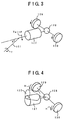
- the hydraulic power transmission joint 127 attempts to tilt as indicated by a chain double-dashed line.
- the hydraulic power transmission joint 127 results by no means in the status of the chain double-dashed line, but instead as in the diagrammatic view of FIG. 5 the housing 105 and the housing shank 104 tend to have a counterclockwise tilt due to a degree of freedom of vertical movement of the propeller shaft 101 in the attached condition.
- the rotor 110 becomes tilted relative to the main shaft 108 as shown in FIGs. 6 and 7.
- the input shaft connecting with the housing is a propeller shaft extending from a front differential gear
- the output shaft connecting with the rotor is a main shaft fitted with a drive gear of a rear differential gear.
- the second bearing retainer having the axially extending extension is further provided in addition to the first bearing retainer provided adjacent to the valve block and press-fitted into the interior of the housing, with the extension of the second bearing retainer having on its outer periphery the second bearing by way of which the second bearing retainer can be supported by the differential gear case, whereby there can be prevented any oil leakage through the gap between the rotor and the valve block leading to a reduction of hydraulic pressure and thus to a lowering of torque, as well as any occurrence of abrasions and noises.
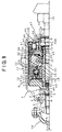
- FIG. 9 is an axial half sectional view of an embodiment of the present invention.
- a companion flange 1 is coupled to a propeller shaft 50 acting as a front wheel input shaft (input shaft).
- a housing shank 2 is inserted into the companion flange 1 and is spline fitted to the latter.
- the housing shank 2 has on its outer periphery a front bearing 3 by way of which the housing shank 2 is supported on a differential gear case 4.
- a seal member 5 and a cover 6 which prevent in cooperation an entrance of dusts or other foreign particles and an outflow of differential gear oil.
- a housing 8 is secured at a weld 7 to the housing shank 2 and has on its inner side surface a cam face 9 having two or more raised portions.
- the housing shank 2 serves as a cam by this cam face 9.
- a rotor 12 is rotatably housed in the housing 8 and engages with a main shaft 13 acting as an output shaft, for rotations in conjunction therewith. From the right side, the main shaft 13 fixedly receives a drive pinion gear 14 associated with a rear differential gear so that the main shaft 13 can rotate jointly with the drive pinion gear 14.
- the rotor 12 is provided with a plurality of axially extending plunger chambers 15 which accommodate a plurality of plungers 16 slidably by way of return springs 17.
- a bearing retainer 34 is provided adjacent to and on the right side of the valve block 27.
- the bearing retainer 34 is fixedly press-fitted at its outer periphery into the housing 8 and is positioned by a snap ring 35.
- the bearing retainer 34 thereby rotates jointly with the housing 8.
- the bearing retainer 34 is formed with a through-hole 36 opening to the low-pressure chamber 19. Needle bearings 37 and 38 are interposed between the bearing retainer 34 and the valve block 27 and between the bearing retainer 34 and the main shaft 13, respectively.
- An oil seal 39 intervenes between the bearing retainer 34 and the main shaft 13, for preventing oil from flowing out.
- the bearing retainer 34 fixedly press-fitted into the housing 8 has an axially extending extension 34A whose outer periphery is provided with a rear bearing 47. The bearing retainer 34 is therefore supported via the rear bearing 47 on the differential gear case 4.
- an accumulator piston 40 is axially slidably provided for absorbing any volume variations of oil arising from thermal expansion or contraction and defines an accumulator chamber 41.
- the accumulator chamber 41 opens to the low-pressure chamber 19 via the through-hole 36 of the bearing retainer 34.
- O-rings 42 and 43 are interposed between the accumulator piston 40 and the housing 8 and between the accumulator piston 40 and the bearing retainer 34, respectively.
- An accumulator retainer 44 is firmly secured at its outer peripheral end to the housing 8.
- a return spring 45 intervenes between the accumulator retainer 44 and the bottom of the accumulator piston 40.
- the opening of the main shaft 13 is provided with an oil groove 48 for lubrication and with a sealing member 49.
- the hydraulic power transmission joint of the present invention is provided with an axially extending extension 34A of the bearing retainer 34 fixedly press-fitted into the housing 8, the extension 34A having at its outer peripheral end the rear bearing 47 by way of which the bearing retainer 34 is supported on the differential gear case 4. This prevents the rotational secondary torque and the thrust-up load exerted on the housing shank 2 from acting on the main shaft 13.
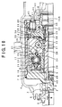
- FIG. 12 illustrates the relationship among the flange, the rotor and the main shaft in another embodiment of the present invention. This structure is applied to the joint shown in FIGs. 9 and 10.
- the housing 8 is welded to the housing shank 2 coupled to the companion flange 1.
- the housing shank 2 On its outer periphery, the housing shank 2 is provided with the front bearing 3 by way of which the housing shank 2 is supported on the differential gear case 4.
- a first bearing retainer 121 identical to that of FIGs. 1 and 2 is fixedly press-fitted into the interior of the housing 8.
- a first needle bearing 124 is interposed between the first bearing retainer 121 and the main shaft 13.
- the first bearing retainer 121 is further followed by a second bearing retainer 51.
- the second bearing retainer 51 is fixedly press-fitted at its outer periphery into the interior end portion of the housing 8.
- An axially extending extension 51A is formed integrally with the inside of the second bearing retainer 51 and has at its outer peripheral end portion a rear bearing 47 acting as a second bearing.
- the second bearing retainer 51 is supported via the rear bearing 47 by the differential gear case 4.
- Rotational secondary torque or thrust-up load input from the propeller shaft 50 passes through the companion flange 1, the front bearing 3, the housing shank 2 and the housing 8 and enters the second bearing retainer 51. After having entered the second bearing retainer 51, the rotational secondary torque or thrust-up load is transmitted to the rear bearing 47 without reaching the main shaft 13.
- the rotor 12 is not tilted relative to the main shaft 13 by any means, resulting in no moment acting to displace the rotor 12 apart from the valve block 27. This prevents any possible leakage through the gap between the valve block 27 and the rotor 12 leading to a reduction of hydraulic pressure and prevents a lowering of the torque.
- Thrust-up load does not act on the main shaft 13, with the result that any abrasions and noises will not occur between the bearing retainer 34 and the main shaft 13.
- an accumulator piston 126 is slidably provided as in FIGs. 1 and 2 between the first bearing retainer 121 and the second bearing retainer 51 of FIG. 12 so as to define an accumulator chamber 41 therebetween, the accumulator chamber 41 being in communication with a low-pressure chamber by way of the first bearing retainer 121.
- the other features are the same as those in FIGs. 1 and 2.
- the axially extending extension is formed on the bearing retainer provided adjacent to the valve block of the joint and press-fitted into the interior of the housing, with the differential gear case bearing being provided on the outer periphery of the extension so that the bearing retainer can be supported via the bearing by the differential gear case, whereby the rotor is prevented from becoming tilted relative to the main shaft in spite of reception of the rotational secondary torque, with the result that there occurs no moment acting to separate the rotor from the valve block, preventing any leakage of oil through the gap between the rotor and the valve block leading to a reduction of hydraulic pressure, as well as preventing any lowering of the torque. Furthermore, the thrust-up load is transmitted to the rear bearing and does not act on the main shaft, thereby making it possible to prevent any occurrence of abrasions and noises.
- the second bearing retainer having the axially extending extension is further provided in addition to the first bearing retainer provided adjacent to the valve block and press-fitted into the interior of the housing, with the extension of the second bearing retainer having on its outer periphery the second bearing by way of which the second bearing retainer can be supported by the differential gear case, there can be prevented any oil leakage through the gap between the rotor and the valve block leading to a reduction of hydraulic pressure and thus to a lowering of torque, as well as any occurrence of abrasions and noises.
Landscapes
- Engineering & Computer Science (AREA)
- General Engineering & Computer Science (AREA)
- Mechanical Engineering (AREA)
- Arrangement And Driving Of Transmission Devices (AREA)
- Retarders (AREA)
- Hydraulic Clutches, Magnetic Clutches, Fluid Clutches, And Fluid Joints (AREA)
Abstract
Description
Claims (5)
- A hydraulic power transmission joint disposed between an input shaft and an output shaft which are capable of relative rotations, for transmitting torque depending on rotational-speed differences between said two shafts, said hydraulic power transmission joint comprising:a housing coupled to said input shaft and having a cam face formed on the inner side of said housing;a rotor coupled to said output shaft and rotatably housed in said housing, said rotor including a plurality of axially extending plunger chambers;a plurality of plungers each accommodated reciprocatively under a pressing force of a return spring in each of said plurality of plunger chambers, said plurality of plungers being operated by said cam face upon relative rotations between said two shafts;a discharge hole formed in said rotor so as to communicate with said plunger chambers;a valve block having a high-pressure chamber which is in communication with said discharge hole, said valve block having an orifice which generates a flow resistance by the flow of oil discharged by the action of said plungers;a bearing retainer provided adjacent to said valve block and having the outer periphery press-fitted into the interior of said housing, said bearing retainer having on its inside an extension which extends in the axial direction of said output shaft; anda bearing by way of which the outer periphery at the terminal end of said extension of said bearing retainer is rotatably supported on the internal side of a differential gear case.
- A hydraulic power transmission joint according to claim 1, whereinsaid input shaft connecting with said housing is a propeller shaft extending from a front differential gear and whereinsaid output shaft connecting with said rotor is a main shaft fitted with a drive gear of a rear differential gear.
- A hydraulic power transmission joint disposed between an input shaft and an output shaft which are capable of relative rotations, for transmitting torque depending on rotational-speed differences between said two shafts, said hydraulic power transmission joint comprising:a housing coupled to said input shaft and having a cam face formed on the inner side of said housing;a rotor coupled to said output shaft and rotatably housed in said housing, said rotor including a plurality of axially extending plunger chambers;a plurality of plungers each accommodated reciprocatively under a pressing force of a return spring in each of said plurality of plunger chambers, said plurality of plungers being operated by said cam face upon relative rotations between said two shafts;a discharge hole formed in said rotor so as to communicate with said plunger chambers;a valve block having a high-pressure chamber which is in communication with said discharge hole, said valve block having an orifice which generates a flow resistance by the flow of oil discharged by the action of said plungers;a first bearing retainer provided adjacent to said valve block;a first bearing by way of which the inner periphery of said first bearing retainer is rotatably supported on said output shaft;a second bearing retainer following said first bearing retainer and having the outer periphery press-fitted into the interior of said housing, said second bearing retainer having on its inside an extension which extends in the axial direction of said output shaft; anda second bearing by way of which the outer periphery at the terminal end of said extension of said second bearing retainer is rotatably supported on the internal side of a differential gear case.
- A hydraulic power transmission joint according to claim 3, whereinsaid input shaft connecting with said housing is a propeller shaft extending from a front differential gear and whereinsaid output shaft connecting with said rotor is a main shaft fitted with a drive gear of a rear differential gear.
- A hydraulic power transmission joint according to claim 3, further comprising an accumulator piston disposed between said first bearing retainer and said second bearing retainer, for absorbing a variation in volume arising from heat of oil.
Applications Claiming Priority (2)
| Application Number | Priority Date | Filing Date | Title |
|---|---|---|---|
| JP11791199 | 1999-04-26 | ||
| JP11791199A JP3658240B2 (en) | 1999-04-26 | 1999-04-26 | Hydraulic power transmission coupling |
Publications (3)
| Publication Number | Publication Date |
|---|---|
| EP1048869A2 true EP1048869A2 (en) | 2000-11-02 |
| EP1048869A3 EP1048869A3 (en) | 2003-01-29 |
| EP1048869B1 EP1048869B1 (en) | 2006-08-30 |
Family
ID=14723239
Family Applications (1)
| Application Number | Title | Priority Date | Filing Date |
|---|---|---|---|
| EP00108385A Expired - Lifetime EP1048869B1 (en) | 1999-04-26 | 2000-04-17 | Hydrostatic coupling |
Country Status (4)
| Country | Link |
|---|---|
| US (1) | US6293381B1 (en) |
| EP (1) | EP1048869B1 (en) |
| JP (1) | JP3658240B2 (en) |
| DE (1) | DE60030352T2 (en) |
Families Citing this family (2)
| Publication number | Priority date | Publication date | Assignee | Title |
|---|---|---|---|---|
| JP3658243B2 (en) * | 1999-05-28 | 2005-06-08 | 株式会社フジユニバンス | Hydraulic power transmission coupling |
| FR3020324B1 (en) * | 2014-04-25 | 2016-04-22 | Poclain Hydraulics Ind | DRIVE ASSEMBLY FOR A MOTOR SHAFT OF A MOTOR VEHICLE |
Citations (1)
| Publication number | Priority date | Publication date | Assignee | Title |
|---|---|---|---|---|
| US5706658A (en) | 1995-01-17 | 1998-01-13 | Fuji Univance Corporation | Rotary shaft coupler with rotary valve plate position dependent on direction of shaft rotation |
Family Cites Families (5)
| Publication number | Priority date | Publication date | Assignee | Title |
|---|---|---|---|---|
| FR2472121A1 (en) * | 1979-12-19 | 1981-06-26 | Retel J R | Torque-limiting hydraulic shaft coupling - has rams bearing on oblique shaft end and acts as piston pump when relative rotation occurs |
| JP2558352B2 (en) * | 1989-07-06 | 1996-11-27 | 株式会社富士鉄工所 | Vehicle power transmission device |
| US5103642A (en) * | 1990-07-12 | 1992-04-14 | Fuji Tekko Co., Ltd. | Rotary shaft coupler with rotary valve plate position dependent on direction of shaft rotation |
| JP2815736B2 (en) * | 1991-10-30 | 1998-10-27 | 株式会社フジユニバンス | Hydraulic power transmission coupling |
| US5297994A (en) * | 1991-12-20 | 1994-03-29 | Fuji Univance Corporation | Hydraulic power transmission joint which is used in vehicles |
-
1999
- 1999-04-26 JP JP11791199A patent/JP3658240B2/en not_active Expired - Fee Related
-
2000
- 2000-04-17 DE DE60030352T patent/DE60030352T2/en not_active Expired - Lifetime
- 2000-04-17 EP EP00108385A patent/EP1048869B1/en not_active Expired - Lifetime
- 2000-04-21 US US09/556,835 patent/US6293381B1/en not_active Expired - Lifetime
Patent Citations (2)
| Publication number | Priority date | Publication date | Assignee | Title |
|---|---|---|---|---|
| US5706658A (en) | 1995-01-17 | 1998-01-13 | Fuji Univance Corporation | Rotary shaft coupler with rotary valve plate position dependent on direction of shaft rotation |
| US5983635A (en) | 1995-01-17 | 1999-11-16 | Fuji Univance Corporation | Rotary shaft coupler with rotary valve plate position dependent on direction of shaft rotation |
Also Published As
| Publication number | Publication date |
|---|---|
| EP1048869A3 (en) | 2003-01-29 |
| JP3658240B2 (en) | 2005-06-08 |
| US6293381B1 (en) | 2001-09-25 |
| EP1048869B1 (en) | 2006-08-30 |
| DE60030352T2 (en) | 2007-08-30 |
| DE60030352D1 (en) | 2006-10-12 |
| JP2000310251A (en) | 2000-11-07 |
Similar Documents
| Publication | Publication Date | Title |
|---|---|---|
| EP1418359B1 (en) | Start clutch device | |
| US20090139818A1 (en) | Torque converter | |
| US6213733B1 (en) | Compressor for the air-conditioning system of a motor vehicle | |
| US5388679A (en) | Torque transmission device of a four-wheel drive vehicle | |
| US6293381B1 (en) | Hydraulic power transmission joint | |
| JPS5923154A (en) | Joint | |
| EP1286066B1 (en) | Pressure regulator assembly for use with a slip joint in a driveshaft assembly | |
| EP1055837B1 (en) | Hydrostatic coupling | |
| US6341682B1 (en) | Hydraulic power transmission joint | |
| EP1055836A2 (en) | Hydrostatic coupling | |
| US5157984A (en) | Sealing device of an automatic transmission | |
| JP3807585B2 (en) | Drain mechanism of hydraulic power transmission joint | |
| JP3699858B2 (en) | Hydraulic power transmission coupling | |
| KR920003233B1 (en) | Working fluid sealed drive coupling | |
| JP3079281B2 (en) | Power steering device | |
| JP4253792B2 (en) | Drain mechanism of hydraulic power transmission joint | |
| US6454070B1 (en) | Drain mechanism for hydraulic power transmission joint | |
| CN218817907U (en) | Power take-off structure and transmission | |
| JPH0861396A (en) | Refueling structure for hydraulic clutch | |
| JP2601909Y2 (en) | Hydraulic power transmission coupling | |
| JP2591928Y2 (en) | Hydraulic power transmission coupling | |
| JPH0351521A (en) | Booster for power transmission device | |
| JP2000310247A (en) | Hydraulic power transmission coupling | |
| JPH07248031A (en) | Hydraulic power transmission coupling | |
| JPH03243422A (en) | Power transmission |
Legal Events
| Date | Code | Title | Description |
|---|---|---|---|
| PUAI | Public reference made under article 153(3) epc to a published international application that has entered the european phase |
Free format text: ORIGINAL CODE: 0009012 |
|
| AK | Designated contracting states |
Kind code of ref document: A2 Designated state(s): AT BE CH CY DE DK ES FI FR GB GR IE IT LI LU MC NL PT SE |
|
| AX | Request for extension of the european patent |
Free format text: AL;LT;LV;MK;RO;SI |
|
| PUAL | Search report despatched |
Free format text: ORIGINAL CODE: 0009013 |
|
| AK | Designated contracting states |
Designated state(s): AT BE CH CY DE DK ES FI FR GB GR IE IT LI LU MC NL PT SE |
|
| AX | Request for extension of the european patent |
Extension state: AL LT LV MK RO SI |
|
| 17P | Request for examination filed |
Effective date: 20030214 |
|
| AKX | Designation fees paid |
Designated state(s): DE FR GB |
|
| GRAP | Despatch of communication of intention to grant a patent |
Free format text: ORIGINAL CODE: EPIDOSNIGR1 |
|
| GRAS | Grant fee paid |
Free format text: ORIGINAL CODE: EPIDOSNIGR3 |
|
| GRAA | (expected) grant |
Free format text: ORIGINAL CODE: 0009210 |
|
| AK | Designated contracting states |
Kind code of ref document: B1 Designated state(s): DE FR GB |
|
| REG | Reference to a national code |
Ref country code: GB Ref legal event code: FG4D |
|
| REF | Corresponds to: |
Ref document number: 60030352 Country of ref document: DE Date of ref document: 20061012 Kind code of ref document: P |
|
| ET | Fr: translation filed | ||
| PLBE | No opposition filed within time limit |
Free format text: ORIGINAL CODE: 0009261 |
|
| STAA | Information on the status of an ep patent application or granted ep patent |
Free format text: STATUS: NO OPPOSITION FILED WITHIN TIME LIMIT |
|
| 26N | No opposition filed |
Effective date: 20070531 |
|
| REG | Reference to a national code |
Ref country code: FR Ref legal event code: PLFP Year of fee payment: 17 |
|
| REG | Reference to a national code |
Ref country code: FR Ref legal event code: PLFP Year of fee payment: 18 |
|
| REG | Reference to a national code |
Ref country code: FR Ref legal event code: PLFP Year of fee payment: 19 |
|
| PGFP | Annual fee paid to national office [announced via postgrant information from national office to epo] |
Ref country code: DE Payment date: 20180430 Year of fee payment: 19 |
|
| PGFP | Annual fee paid to national office [announced via postgrant information from national office to epo] |
Ref country code: GB Payment date: 20180403 Year of fee payment: 19 |
|
| PGFP | Annual fee paid to national office [announced via postgrant information from national office to epo] |
Ref country code: FR Payment date: 20190423 Year of fee payment: 20 |
|
| REG | Reference to a national code |
Ref country code: DE Ref legal event code: R119 Ref document number: 60030352 Country of ref document: DE |
|
| GBPC | Gb: european patent ceased through non-payment of renewal fee |
Effective date: 20190417 |
|
| PG25 | Lapsed in a contracting state [announced via postgrant information from national office to epo] |
Ref country code: DE Free format text: LAPSE BECAUSE OF NON-PAYMENT OF DUE FEES Effective date: 20191101 Ref country code: GB Free format text: LAPSE BECAUSE OF NON-PAYMENT OF DUE FEES Effective date: 20190417 |