EP1048556A1 - A device for reducing the aerodynamic resistance of a motor vehicle - Google Patents
A device for reducing the aerodynamic resistance of a motor vehicle Download PDFInfo
- Publication number
- EP1048556A1 EP1048556A1 EP00108437A EP00108437A EP1048556A1 EP 1048556 A1 EP1048556 A1 EP 1048556A1 EP 00108437 A EP00108437 A EP 00108437A EP 00108437 A EP00108437 A EP 00108437A EP 1048556 A1 EP1048556 A1 EP 1048556A1
- Authority
- EP
- European Patent Office
- Prior art keywords
- motor vehicle
- air stream
- duct
- source
- auxiliary air
- Prior art date
- Legal status (The legal status is an assumption and is not a legal conclusion. Google has not performed a legal analysis and makes no representation as to the accuracy of the status listed.)
- Withdrawn
Links
- 238000000926 separation method Methods 0.000 description 3
- 230000000694 effects Effects 0.000 description 2
- 238000005192 partition Methods 0.000 description 1
Images


Classifications
-
- B—PERFORMING OPERATIONS; TRANSPORTING
- B62—LAND VEHICLES FOR TRAVELLING OTHERWISE THAN ON RAILS
- B62D—MOTOR VEHICLES; TRAILERS
- B62D35/00—Vehicle bodies characterised by streamlining
Definitions
- the present invention relates to a device for reducing the aerodynamic resistance of a motor vehicle, which includes means for deflecting an external air stream which flows over an external surface of the body of the motor vehicle during its forward movement, arranged near an edge of a rear end panel of the motor vehicle.
- Known devices of the type described above are commonly used on the rear portion or tail of the body of a motor vehicle to alter the flow of air in the wake caused by the movement of the vehicle, in order to reduce the aerodynamic resistance thereof during its forward movement.
- the air stream in the wake of a moving motor vehicle can be considered as the resultant of a predominantly two-dimensional stream composed of a pair of counter-rotating vortices formed behind the tail of the motor vehicle and of a predominantly three-dimensional stream, essentially constituted by two high-intensity symmetrical, counter-rotating longitudinal vortices set up by the air flowing past the rear pillars of the motor vehicle body and which thus depends on the inclination of the said pillars, since the said longitudinal vortices are comparable to a pair of vortices at the tip of a short wing.
- the drag of a moving motor vehicle depends, to a first approximation, on phenomena involved in the separation of the said two-dimensional and three-dimensional air streams which generate pressure resistance.
- a reduction in the phenomena caused by separation of the two-dimensional and three-dimensional components of the wake at the tail of a moving motor vehicle translates into a reduction in the drag of the motor vehicle.
- auxiliary wings or sharp corners commonly known as "aerodynamic spoilers”
- aerodynamic spoilers are often used, normally arranged at the upper edge of the rear panel of a motor vehicle.
- the spoiler makes it possible to alter the separation of the air streams described above, by varying resistance to pressure so as to determine a significant reduction in the drag coefficient of the motor vehicle, and thus of its overall drag.
- the object of the present invention is to provide a device of the aforementioned type, characterised in that the means for deflecting the external airflow include at least one source of an auxiliary airflow directed substantially transverse the external airflow so as to interfere therewith.
- the invention it is possible to provide a device for reducing the aerodynamic resistance of a motor vehicle which does not require the presence of supplementary aerodynamic appendages at the upper edge of the tail end of the motor vehicle, and which is able to achieve a similar reduction in drag to that achieved by aerodynamic appendage devices known in the prior art.
- the rear wall 4 is joined to the upper surface of a lid 5a of a boot by an upper edge 5 with a relatively wide radius of curvature.
- a flattened duct 7 is associated with the wall 4, extending the length thereof, transverse the longitudinal direction of the motor vehicle 1 and closed along its lateral edges.
- the duct 7 opens just beneath the edge 5 and acts as the source of an auxiliary air stream A directed transverse the external air stream B which flows over the body 1, so as to interfere therewith and thereby alter the air stream in its wake.
- the air stream A is supplied to the duct 7 during forward motion of the car 1 through a lower front aperture 11 formed so as to constitute a dynamic air intake opening under the body 1 of the motor vehicle.
- the air stream A exits from the duct 7 through an upper outlet 15, opposite the air intake 11, oriented so as to direct the air stream A upwards in order to blow air towards the edge 5 and thereby interfere with the air stream B.
- the duct 7 is preferably made in two communicating parts: a lower portion 9 formed on the inner surface of the bumper 9a by means of partitions, possibly made of a softer material than that of the bumper itself, and an upper portion 13, partly formed by a channel formed by the inner covering of the back wall 4 of the lid 5a, in such a way that only a small portion of the duct 7, substantially at the site of the opening 15, protrudes from the back wall 4.
- the upper portion 13 of the duct 7 can be delimited at the back, near the opening 15, by a number-plate bracket 18 (See Figure 4) for the motor vehicle 1, in such a way that the presence of the device of the invention has only the smallest effect on the aesthetics of the tail of the motor vehicle 1.
- the device of the invention proved able, in trials conducted by the Applicant, to achieve the same reduction in aerodynamic resistance as that obtainable with a conventional aerodynamic spoiler.
- the achieved drag reduction remained substantially constant over a range of speed of the car of around 80 to 140 km/h.
- the outlet aperture of a device according to the invention used in the trials was around 2 cm long and around 70 cm wide, measured with respect to the longitudinal axis of the motor vehicle, and the performance compared with that achieved with a spoiler having a wing having an arcuate plan form, around 100 cm wide and at most 15 cm long at its central portion, arranged at the edge 5.
Landscapes
- Engineering & Computer Science (AREA)
- Chemical & Material Sciences (AREA)
- Combustion & Propulsion (AREA)
- Transportation (AREA)
- Mechanical Engineering (AREA)
- Apparatuses And Processes For Manufacturing Resistors (AREA)
- Non-Adjustable Resistors (AREA)
- Details Of Resistors (AREA)
- Body Structure For Vehicles (AREA)
Abstract
Description
- The present invention relates to a device for reducing the aerodynamic resistance of a motor vehicle, which includes means for deflecting an external air stream which flows over an external surface of the body of the motor vehicle during its forward movement, arranged near an edge of a rear end panel of the motor vehicle.
- Known devices of the type described above are commonly used on the rear portion or tail of the body of a motor vehicle to alter the flow of air in the wake caused by the movement of the vehicle, in order to reduce the aerodynamic resistance thereof during its forward movement.
- The air stream in the wake of a moving motor vehicle can be considered as the resultant of a predominantly two-dimensional stream composed of a pair of counter-rotating vortices formed behind the tail of the motor vehicle and of a predominantly three-dimensional stream, essentially constituted by two high-intensity symmetrical, counter-rotating longitudinal vortices set up by the air flowing past the rear pillars of the motor vehicle body and which thus depends on the inclination of the said pillars, since the said longitudinal vortices are comparable to a pair of vortices at the tip of a short wing.
- In particular, the drag of a moving motor vehicle depends, to a first approximation, on phenomena involved in the separation of the said two-dimensional and three-dimensional air streams which generate pressure resistance. As a result, a reduction in the phenomena caused by separation of the two-dimensional and three-dimensional components of the wake at the tail of a moving motor vehicle translates into a reduction in the drag of the motor vehicle.
- In order to achieve such a reduction, it is necessary to act on the shape of the rear portion of the motor vehicle, that is on the angle of inclination and the length of the said portion, and in particular on the radius of curvature at the edges joining the body panels, and on the geometry of the base of the body.
- In order to achieve a macroscopic effect on the vortex drag of a motor vehicle, appendages in the shape of auxiliary wings or sharp corners, commonly known as "aerodynamic spoilers", are often used, normally arranged at the upper edge of the rear panel of a motor vehicle.
- The spoiler makes it possible to alter the separation of the air streams described above, by varying resistance to pressure so as to determine a significant reduction in the drag coefficient of the motor vehicle, and thus of its overall drag.
- However, use of spoilers on the body of a motor vehicle can be unwelcome, since it restricts design options and can interfere with the line of the rear portion of the motor vehicle.
- In order to solve this problem, the object of the present invention is to provide a device of the aforementioned type, characterised in that the means for deflecting the external airflow include at least one source of an auxiliary airflow directed substantially transverse the external airflow so as to interfere therewith.
- Thanks to the invention, it is possible to provide a device for reducing the aerodynamic resistance of a motor vehicle which does not require the presence of supplementary aerodynamic appendages at the upper edge of the tail end of the motor vehicle, and which is able to achieve a similar reduction in drag to that achieved by aerodynamic appendage devices known in the prior art.
- Further characteristics and advantages of the present invention will become apparent from the detailed description which follows, provided with reference to the appended drawings, supplied purely by way of non-limitative example, in which:
- Figure 1 is a partially sectioned side elevation view of the rear portion of a first motor vehicle,
- Figure 2 is an enlarged schematic view of a detail indicated by the arrow II in Figure 1,
- Figure 3 is a similar view to Figure 1 of a different motor vehicle, and
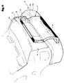
- Figure 4 is a schematic perspective view which offers in a fragmented manner illustrations of the main components of a device according to the invention.
-
- With reference first to Figures 1, 2 and 4, the rear portion or tail of a motor vehicle body 1, having a so-called three-box or "notch-back" body, is indicated 3. In particular, the
rear wall 4 is joined to the upper surface of a lid 5a of a boot by anupper edge 5 with a relatively wide radius of curvature. - A
flattened duct 7 is associated with thewall 4, extending the length thereof, transverse the longitudinal direction of the motor vehicle 1 and closed along its lateral edges. Theduct 7 opens just beneath theedge 5 and acts as the source of an auxiliary air stream A directed transverse the external air stream B which flows over the body 1, so as to interfere therewith and thereby alter the air stream in its wake. - In particular, the air stream A is supplied to the
duct 7 during forward motion of the car 1 through alower front aperture 11 formed so as to constitute a dynamic air intake opening under the body 1 of the motor vehicle. The air stream A exits from theduct 7 through anupper outlet 15, opposite theair intake 11, oriented so as to direct the air stream A upwards in order to blow air towards theedge 5 and thereby interfere with the air stream B. - The
duct 7 is preferably made in two communicating parts: a lower portion 9 formed on the inner surface of thebumper 9a by means of partitions, possibly made of a softer material than that of the bumper itself, and anupper portion 13, partly formed by a channel formed by the inner covering of theback wall 4 of the lid 5a, in such a way that only a small portion of theduct 7, substantially at the site of theopening 15, protrudes from theback wall 4. - The
upper portion 13 of theduct 7 can be delimited at the back, near the opening 15, by a number-plate bracket 18 (See Figure 4) for the motor vehicle 1, in such a way that the presence of the device of the invention has only the smallest effect on the aesthetics of the tail of the motor vehicle 1. - In Figure 3, in which the same reference numbers have been used to indicate parts which are the same as, or similar to those of Figure 1, the invention is applied to a motor vehicle 1a with a two-and-a-half box body, a so-called fast-back, that is having a sharply inclined surface between the rear edge of the roof and the
upper edge 5 of therear wall 4. - Then applied either to three-box, or notch-back bodies or to two-and-a-half box or fast-back bodies, that is bodies with relatively high tails, the device of the invention proved able, in trials conducted by the Applicant, to achieve the same reduction in aerodynamic resistance as that obtainable with a conventional aerodynamic spoiler. In particular, the achieved drag reduction remained substantially constant over a range of speed of the car of around 80 to 140 km/h.
- The outlet aperture of a device according to the invention used in the trials was around 2 cm long and around 70 cm wide, measured with respect to the longitudinal axis of the motor vehicle, and the performance compared with that achieved with a spoiler having a wing having an arcuate plan form, around 100 cm wide and at most 15 cm long at its central portion, arranged at the
edge 5. - The trials also revealed that when using both a conventional wing spoiler and a device of the invention at the site of the
upper edge 5 of therear wall 4 of a motor vehicle, their capacity to reduce aerodynamic resistance partly combine to give a total reduction in drag greater than that achieved with either the wing spoiler or the device of the invention alone.
Claims (7)
- A device for reducing the aerodynamic resistance of a motor vehicle, comprising means (15) for deflecting an external air stream (B) which flows over the external surface of the body (1, 1a) of the motor vehicle during its forward movement, disposed close to an edge (5) of a rear end wall (4) of the motor vehicle,
characterised in that the means for deflecting the external air stream (B) comprise at least one source (15) of an auxiliary air stream (A) directed substantially transverse the external air stream (B) so as to interfere therewith. - A device according to Claim 1, characterised in that the source (15) of the auxiliary air stream (A) is located near the upper edge (5) of the said rear end wall (4) of the motor vehicle, thereby directing the auxiliary air stream (A) upwardly.
- A device according to Claim 2, characterised in that the source of the auxiliary air stream (A) has an elongate outlet opening (15) which extends transversely of the motor vehicle (1, 1a) along the rear end wall (4) thereof, just beneath its upper edge (5).
- A device according to any one of Claims 1 to 3, characterised in that it includes a generally flattened duct (7) having a first end with at least one dynamic air intake (11), facing forwardly relative to the forward direction of the motor vehicle, and a second end provided with the said outlet opening (15).
- A device according to Claim 4, characterised in that the said at least one dynamic air intake (11) opens in correspondence with the bottom of the body.
- A device according to Claim 5, characterised in that the duct (7) includes a first portion (9) arranged along an inner surface of the rear bumper (9a) of the car (1, 1a) and connected to a second portion (13) arranged along a rear wall (4) of a rear boot lid (5a) of the motor vehicle.
- A device according to Claim 6, characterised in that the second portion (13) of the duct is delimited by a number plate holder (18) of the motor vehicle.
Applications Claiming Priority (2)
| Application Number | Priority Date | Filing Date | Title |
|---|---|---|---|
| ITTO990335 | 1999-04-26 | ||
| IT1999TO000335A IT1308455B1 (en) | 1999-04-26 | 1999-04-26 | DEVICE FOR THE REDUCTION OF THE AERODYNAMIC RESISTANCE OF A VEHICLE |
Publications (1)
| Publication Number | Publication Date |
|---|---|
| EP1048556A1 true EP1048556A1 (en) | 2000-11-02 |
Family
ID=11417755
Family Applications (1)
| Application Number | Title | Priority Date | Filing Date |
|---|---|---|---|
| EP00108437A Withdrawn EP1048556A1 (en) | 1999-04-26 | 2000-04-18 | A device for reducing the aerodynamic resistance of a motor vehicle |
Country Status (2)
| Country | Link |
|---|---|
| EP (1) | EP1048556A1 (en) |
| IT (1) | IT1308455B1 (en) |
Cited By (6)
| Publication number | Priority date | Publication date | Assignee | Title |
|---|---|---|---|---|
| US6561575B2 (en) | 2001-08-23 | 2003-05-13 | Vacuum Breaker Mile Maker | Air channeler for reducing wind resistance and method of use |
| FR2885343A1 (en) * | 2005-05-03 | 2006-11-10 | Peugeot Citroen Automobiles Sa | Aerodynamic lift and drag reducing system for motor vehicle e.g. minivan, has scoop arranged below understructure of vehicle and having outlet connected to holes arranged in downstream or upstream or at vortex zone at rear of vehicle |
| KR20170024446A (en) * | 2015-08-25 | 2017-03-07 | 현대모비스 주식회사 | Rear bumper of vehicle |
| DE102015121814A1 (en) * | 2015-12-15 | 2017-06-22 | Dr. Ing. H.C. F. Porsche Aktiengesellschaft | Outlet device for the outlet of exhaust gas of an internal combustion engine of a vehicle |
| JP2017531590A (en) * | 2014-10-14 | 2017-10-26 | アストン マーティン ラゴンダ リミテッドAston Martin Lagonda Limited | Vehicle airflow control device |
| US12000329B2 (en) | 2018-12-17 | 2024-06-04 | Aston Martin Lagonda Limited | Assemblies for engines |
Citations (6)
| Publication number | Priority date | Publication date | Assignee | Title |
|---|---|---|---|---|
| US1923349A (en) * | 1932-07-09 | 1933-08-22 | Julia N Larson | Vacuum breaker |
| US2037942A (en) * | 1935-10-28 | 1936-04-21 | Edward A Stalker | Means of reducing the fluid resistance of propelled vehicles |
| US2199883A (en) * | 1938-03-17 | 1940-05-07 | Ishiwata Zenzo | Apparatus for preventing raising of dust and splashing of mud by automobiles |
| US4772062A (en) * | 1986-07-30 | 1988-09-20 | Bayerische Motoren Werke Aktiengesellschaft | Motor vehicle, especially passenger motor vehicle |
| WO1997011874A1 (en) * | 1995-09-25 | 1997-04-03 | Cke Technologies Inc. | Aerodynamic automobile |
| DE19633205A1 (en) * | 1996-08-17 | 1998-02-19 | Porsche Ag | Device for generating downwards force on rear axle of vehicle |
-
1999
- 1999-04-26 IT IT1999TO000335A patent/IT1308455B1/en active
-
2000
- 2000-04-18 EP EP00108437A patent/EP1048556A1/en not_active Withdrawn
Patent Citations (6)
| Publication number | Priority date | Publication date | Assignee | Title |
|---|---|---|---|---|
| US1923349A (en) * | 1932-07-09 | 1933-08-22 | Julia N Larson | Vacuum breaker |
| US2037942A (en) * | 1935-10-28 | 1936-04-21 | Edward A Stalker | Means of reducing the fluid resistance of propelled vehicles |
| US2199883A (en) * | 1938-03-17 | 1940-05-07 | Ishiwata Zenzo | Apparatus for preventing raising of dust and splashing of mud by automobiles |
| US4772062A (en) * | 1986-07-30 | 1988-09-20 | Bayerische Motoren Werke Aktiengesellschaft | Motor vehicle, especially passenger motor vehicle |
| WO1997011874A1 (en) * | 1995-09-25 | 1997-04-03 | Cke Technologies Inc. | Aerodynamic automobile |
| DE19633205A1 (en) * | 1996-08-17 | 1998-02-19 | Porsche Ag | Device for generating downwards force on rear axle of vehicle |
Cited By (9)
| Publication number | Priority date | Publication date | Assignee | Title |
|---|---|---|---|---|
| US6561575B2 (en) | 2001-08-23 | 2003-05-13 | Vacuum Breaker Mile Maker | Air channeler for reducing wind resistance and method of use |
| US6692066B2 (en) | 2001-08-23 | 2004-02-17 | Vacuum Breaker Mile Maker | Air channeler for reducing wind resistance and method of use |
| FR2885343A1 (en) * | 2005-05-03 | 2006-11-10 | Peugeot Citroen Automobiles Sa | Aerodynamic lift and drag reducing system for motor vehicle e.g. minivan, has scoop arranged below understructure of vehicle and having outlet connected to holes arranged in downstream or upstream or at vortex zone at rear of vehicle |
| JP2017531590A (en) * | 2014-10-14 | 2017-10-26 | アストン マーティン ラゴンダ リミテッドAston Martin Lagonda Limited | Vehicle airflow control device |
| US10040491B2 (en) | 2014-10-14 | 2018-08-07 | Aston Martin Lagonda Limited | Vehicle airflow control apparatus |
| KR20170024446A (en) * | 2015-08-25 | 2017-03-07 | 현대모비스 주식회사 | Rear bumper of vehicle |
| DE102015121814A1 (en) * | 2015-12-15 | 2017-06-22 | Dr. Ing. H.C. F. Porsche Aktiengesellschaft | Outlet device for the outlet of exhaust gas of an internal combustion engine of a vehicle |
| US12000329B2 (en) | 2018-12-17 | 2024-06-04 | Aston Martin Lagonda Limited | Assemblies for engines |
| US12535029B2 (en) | 2018-12-17 | 2026-01-27 | Aston Martin Lagonda Limited | Assemblies for engines |
Also Published As
| Publication number | Publication date |
|---|---|
| IT1308455B1 (en) | 2001-12-17 |
| ITTO990335A1 (en) | 2000-10-26 |
| ITTO990335A0 (en) | 1999-04-26 |
Similar Documents
| Publication | Publication Date | Title |
|---|---|---|
| US4379582A (en) | Device for improving aerodynamic and safety characteristics of automotive vehicles | |
| US7604284B2 (en) | Vehicle fairing structure | |
| US5842734A (en) | Device for reducing the aerodynamic resistance of a vehicle preferably a utility vehicle | |
| US8641126B2 (en) | Sealed aft cavity drag reducer | |
| US4210354A (en) | Aerodynamic drag-reducing shield for mounting on the front of a cargo carrying compartment of a road vehicle | |
| US20210188373A1 (en) | Reducing Aerodynamic Drag of Semi-trailer Truck | |
| EP1870321B1 (en) | A system for optimizing the aerodynamics of the rear part of an industrial or commercial vehicle | |
| US4867397A (en) | Vehicle aerodynamic drag reduction system and process | |
| CN212022801U (en) | Aerodynamic device, hood device and grille for a vehicle, and vehicle | |
| US10040491B2 (en) | Vehicle airflow control apparatus | |
| US6669270B1 (en) | Truck wind deflector | |
| US20250115311A1 (en) | Vehicle aerodynamics | |
| US20090302639A1 (en) | Vehicle having aerodynamic fan elements | |
| JP2012126178A (en) | Rear spoiler | |
| CN101166659A (en) | System for reducing fuel consumption of vehicle | |
| CA1096905A (en) | Vehicle air spoiler | |
| US5934740A (en) | Air guiding device | |
| JPS61249879A (en) | Aerodynamic device for passenger car | |
| US5671970A (en) | Wind deflector for motor vehicle sunroof | |
| FR2613682A1 (en) | Device making it possible for vehicles to improve their penetration through the air (correction of Cx) | |
| CN110294027A (en) | Foot passage vortex generator | |
| US20160339971A1 (en) | Wake convergence device for a pick-up truck | |
| JP2002120769A (en) | Body structure | |
| US5871254A (en) | Pickup truck tailgate mounted aerostabilizer | |
| US6012762A (en) | Drag reducing aerostabilizer for pickup trucks |
Legal Events
| Date | Code | Title | Description |
|---|---|---|---|
| PUAI | Public reference made under article 153(3) epc to a published international application that has entered the european phase |
Free format text: ORIGINAL CODE: 0009012 |
|
| AK | Designated contracting states |
Kind code of ref document: A1 Designated state(s): AT BE CH CY DE LI |
|
| AX | Request for extension of the european patent |
Free format text: AL;LT;LV;MK;RO;SI |
|
| AKX | Designation fees paid |
Free format text: AT BE CH CY DE LI |
|
| 17P | Request for examination filed |
Effective date: 20010405 |
|
| RBV | Designated contracting states (corrected) |
Designated state(s): DE ES FR GB SE |
|
| 17Q | First examination report despatched |
Effective date: 20030515 |
|
| STAA | Information on the status of an ep patent application or granted ep patent |
Free format text: STATUS: THE APPLICATION IS DEEMED TO BE WITHDRAWN |
|
| 18D | Application deemed to be withdrawn |
Effective date: 20030926 |