EP1048536A2 - A seat belt retractor - Google Patents
A seat belt retractor Download PDFInfo
- Publication number
- EP1048536A2 EP1048536A2 EP00303424A EP00303424A EP1048536A2 EP 1048536 A2 EP1048536 A2 EP 1048536A2 EP 00303424 A EP00303424 A EP 00303424A EP 00303424 A EP00303424 A EP 00303424A EP 1048536 A2 EP1048536 A2 EP 1048536A2
- Authority
- EP
- European Patent Office
- Prior art keywords
- pawl
- spool
- support
- ratchet
- mass
- Prior art date
- Legal status (The legal status is an assumption and is not a legal conclusion. Google has not performed a legal analysis and makes no representation as to the accuracy of the status listed.)
- Granted
Links
Images



Classifications
-
- B—PERFORMING OPERATIONS; TRANSPORTING
- B60—VEHICLES IN GENERAL
- B60R—VEHICLES, VEHICLE FITTINGS, OR VEHICLE PARTS, NOT OTHERWISE PROVIDED FOR
- B60R22/00—Safety belts or body harnesses in vehicles
- B60R22/34—Belt retractors, e.g. reels
- B60R22/36—Belt retractors, e.g. reels self-locking in an emergency
- B60R22/405—Belt retractors, e.g. reels self-locking in an emergency responsive to belt movement and vehicle movement
-
- B—PERFORMING OPERATIONS; TRANSPORTING
- B60—VEHICLES IN GENERAL
- B60R—VEHICLES, VEHICLE FITTINGS, OR VEHICLE PARTS, NOT OTHERWISE PROVIDED FOR
- B60R22/00—Safety belts or body harnesses in vehicles
- B60R22/34—Belt retractors, e.g. reels
- B60R22/36—Belt retractors, e.g. reels self-locking in an emergency
- B60R22/40—Belt retractors, e.g. reels self-locking in an emergency responsive only to vehicle movement
- B60R2022/401—Belt retractors, e.g. reels self-locking in an emergency responsive only to vehicle movement with adjustable sensor
Definitions
- the invention relates to a seat belt retractor.
- a retractor for a vehicle seat belt contains a vehicle sensor, which responds to changes in the vehicle acceleration or deceleration occurring in a vehicle crash.
- the webbing sensor detects payout of the webbing from the retractor due to the movement of a vehicle occupant when the vehicle decreases or increases in speed.
- the vehicle sensor comprises an inertia mass either in the form of a ball or a hollow shaped tube acting on a pin or a mass with a relatively high centre of gravity located above a narrow base.
- Movement of the mass acts on a lever positioned in close proximity to the mass to move a toothed portion of the lever into engagement with teeth on a spool or a ratchet thus initiating the locking of the retractor spool and preventing further payout of the webbing.
- a typical retractor, including the vehicle sensor, is formed by many cooperating components.
- each component can vary in size due to environmental changes such as changes in temperature during the component manufacturing process.
- components vary in dimensions when made in multi cavity tools where more than one component is moulded in sequence or at the same time.
- the moulding tool may deteriorate or wear causing variation in component sizes.
- the variation in sizes creates variability in the relationship between each component. This is particularly undesirable in the vehicle sensor as the spacing between the spool teeth and the vehicle sensor locking teeth requires precision. Variation in the gap between the spool or ratchet teeth and the vehicle sensor locking tooth gives poor repeatability of the vehicle sensor performance.
- the space between the spool or ratchet teeth and the vehicle sensor locking tooth is called the "tip gap".
- the vehicle sensor lever may engage with the spool teeth and lock the retractor in a non-emergency situation. That can create discomfort for the occupant with the seat belt "jamming".
- a seat belt retractor comprising a frame, a spool rotatably mounted to the frame, a spool locking device for locking the spool to prevent rotation thereof, actuating means for actuating the spool locking device comprising a support carrying a mass and a pawl, the mass being arranged to move from an initial position to an actuating position to actuate the pawl into engagement with a ratchet on the spool whereby engagement of the pawl with the ratchet actuates the spool locking device, the support being arranged to pivot so as to adjust the distance between the pawl and the ratchet.
- the position of the pawl can be adjusted to provide an optimum gap between the pawl tip and the ratchet on the spool.
- the pawl is arranged to one side of the support and the support is pivotal about a longitudinal axis thereof.
- the support preferably comprises a base having a recess and two end walls upstanding from opposite edges of the base, the mass being received in the recess and the pawl being arranged over the mass, pivotally mounted to an upper part of one end wall.
- the support preferably includes respective pivot members extending from each end wall to enable the support to be pivotally mounted to the frame.
- a seat belt retractor comprising a frame, a spool rotatably mounted to the frame, a spool locking device for locking the spool to prevent rotation thereof, actuating means for actuating the spool locking device comprising a support carrying a mass and a pawl, the mass being arranged to move from an initial position to an actuating position to actuate the pawl into engagement with a ratchet on the spool whereby engagement of the pawl with the ratchet actuates the spool locking device, the spool having a cam formation with a circular cam periphery arranged substantially coaxially therewith, the support having a cam follower, the support being mounted movably relative to the spool in response to movement of the cam follower.
- the position of the pawl tip relative to the ratchet can continually be adjusted in response to, for example, irregularities in the concentricity of the spool.
- the support is pivotably mounted to the frame so that movement of the cam follower causes the support to pivot so as to effect automatic tip gap adjustment.
- a seat belt retractor comprising a frame, a spool rotably mounted to the frame, a spool locking device for locking the spool to prevent rotation thereof, actuating means for actuating the spool locking device comprising a support carrying a mass and a pawl, the mass being arranged to move from an initial position to an actuating position to actuate the pawl into engagement with a ratchet on the spool whereby engagement of the pawl with the ratchet actuates the spool locking device, the actuating means comprising a pawl actuating lever pivotally mounted to the support and arranged between the mass and the pawl, the pawl including a cam surface, the pawl actuating lever engaging the cam surface whereby movement of the pawl actuating lever along the cam surface adjusts the distance between the pawl and the ratchet.
- the movement of the pawl actuating lever along the cam surface is effected by means of a movement mechanism comprising a pivot pin which pivotally mounts the pawl actuating lever and a pivot peg extending from the pivot pin, parallel with and offset from the axis thereof, and received in the support, whereby rotation of the pivot peg effects movement of the pawl actuating lever along the cam surface.
- a seat belt retractor comprising a frame, a spool rotatably mounted to the frame, a spool locking device for locking the spool to prevent rotation thereof, actuating means for actuating the spool locking device comprising a support carrying a mass and a pawl, the mass being arranged to move from an initial position to an actuating position to actuate the pawl into engagement with a ratchet on the spool whereby engagement of the pawl with the ratchet actuates the spool locking device, the mass engaging the underside of the pawl, the underside of the pawl having a cam surface thereon whereby movement of the mass relative to the pawl along the cam surface effects adjustment of the distance between the pawl and the ratchet.
- movement of the pawl is effected by a movement mechanism which comprises a pivot pin which pivotally mounts the pawl and a pivot peg extending from the pivot pin, parallel with and offset from the axis thereof, and received in the support, whereby rotation of the pivot peg effects relative movement of the pawl and mass.
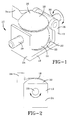
- the support 12 comprises a base 18 having a substantially circular recess 20 formed therein with sloping side walls 22.
- the support 12 further comprises end walls 24, 26 which are arranged upstanding from opposite ends of the base 18.
- a spigot 28 extends perpendicularly outwardly from the end wall 24, from the face of the end wall facing away from the other end wall.
- a spigot 30 extends perpendicularly outwardly from the end wall 26 from the face of the end wall 26 facing away from the other end wall 24.
- the spigots 28, 30 are arranged co-axially with respect to each other.
- the inertial mass 14 is arranged in the recess 20.
- the pawl 16 is pivotally mounted to the upper part of the end wall 26 of the support 12.
- the pawl 16 comprises a curved cap 32 and a pawl tooth 34 arranged at one side of the cap 32.
- the cap 32 is arranged over the spherical mass 14 so as to cover part of the mass 14 and the tooth 34 extends upwardly from said one side of the cap 32 towards a ratchet on a retractor spool (not shown).
- the function of the vehicle sensor is described in detail above and will not be gone into here. As mentioned above, it is necessary to adjust the gap between the tip of the pawl tooth 34 and the teeth of the ratchet (not shown) after assembly of the sensor into the retractor spool.
- the support 12 of the vehicle sensor 10 is pivotally mounted to the retractor by means of the spigots 28, 30.
- the spigots 28, 30 are received with an interference fit in a retractor so that, once adjusted, the support 12 does not return to its initial position by means of, for example, vibration of the vehicle in which the retractor is located.
- the surface of one or more of the spigots 28, 30 may be crenellated and a tang may be provided in the recess in which the spigot is received in the retractor so that a positive engagement is effected to prevent the support 12 from moving out of position.
- FIG. 3 an alternative arrangement of seat belt retractor in accordance with the first and second aspect of the invention is shown.
- the vehicle sensor 10 is arranged in a retractor (not shown) adjacent a ratchet 36 of the retractor. Parts corresponding to parts in Figs. 1 and 2 carry the same reference numerals.
- the sensor 10 comprises a support 12, an inertial mass 14 and a pawl 16.
- the support 12 is similar to that shown in Fig. 1 except the end wall 24 is omitted, as are the mounting spigots 28, 30. Instead, the support 12 includes an extending base part 38 extending from the end wall 24 in a direction away from the inertia mass 14.
- the extended base part 38 has an upstanding member 40 which is pivotally mounted at pivot point 42 to the retractor.
- the upstanding member 40 has a cam follower member 44 extending from an upper part thereof.
- the cam follower 44 includes a cam follower finger 46 projecting transversely from one end thereof towards a circular cam surface 48 arranged on the ratchet 36.
- the cam surface 48 is arranged co-axially of the ratchet 36
- a leaf spring 50 is arranged beneath the support 12 engaging the underside of the base 18 so as to bias the support 12 towards the ratchet 36.
- the support 12 is adjusted initially on assembly by rotating the support 12 about the pivot point 42 so as to correct the gap between the tip of the pawl tooth 34 and the teeth of the ratchet 36.
- errors in the concentricity of the axis of the ratchet 36 may produce variations in the gap between the pawl tooth 34 and the teeth of the ratchet 36.
- that gap is corrected automatically by means of the cam follower 44.
- the finger 46 of the cam follower 44 follows the circular cam surface 48 which is arranged co-axially of the ratchet 36.
- any vertical movement of the ratchet 36 will result in a corresponding movement of the support 12 about the axis 42. If the ratchet 36 moves upwardly in Fig. 3 the leaf spring 50 will bias the support 12 upwardly by corresponding distance. If the ratchet 36 moves downwardly the cam surface 48 will act against the cam follower 44 so as to push the support 12 downwardly against the bias of the spring 50.
- a further pawl/pawl actuation arrangement is shown.
- the pawl 16 is carried by a pawl adjustment lever 51.
- the pawl 16 has a cam surface 52 formed thereon on the underside thereof.
- the pawl 16 is actuated by means of a pawl actuating lever 53 which itself is arranged over the inertial mass 14 on the support 12.
- the pawl adjustment lever 51 is pivoted on the frame of the retractor spool at pivot point 54.
- the pawl adjustment lever 51 carries the pawl 16 from a depending spur 55.
- the pawl is pivotally mounted to the spur 55.
- the pawl adjustment lever 51 further comprises a cam follower part 56 similar to the cam follower shown in Fig.3.
- the cam follower part 56 follows the circular cam surface 48 arranged co-axially of the ratchet 36. In use, as the ratchet rotates the cam follower 56 follows the circular cam surface 48 so that any vertical movement of the ratchet 36 due to manufacturing errors will result in a corresponding movement of the cam follower 56.
- Fig.7 is similar in many respects to the arrangement shown in Fig.6. However, the mechanism is less direct in its action.
- the pawl 16 is carried by the frame of the ratchet 36. Again, the pawl 16 has a cam surface 52 on the underside thereof.
- the pawl 16 is pivotally mounted to the frame of the ratchet 36 at pivot point 57.
- a pawl adjustment lever 51 having a cam follower 56 engaging a cam surface 48 on the ratchet 36 is provided.
- the pawl adjustment lever 51 comprises an L-shaped body having the cam follower 56 at one free end and being pivotally connected to a further lever mechanism generally indicated at 58 at its other end at pivot point 59.
- the lever mechanism 58 comprises a solid lever member 60 connected via pivot point 59 to the pawl adjustment lever 51 at one end.
- the lever 60 is mounted on a fulcrum 61 comprising part of the support 12 of the inertia mass 14 and the other end of the lever 60 carries the pawl actuating lever 53 by means of pivotal linkage 62.
- the cam follower 56 follows the surface 48 on the ratchet 36 to adjust for movement of the ratchet due to manufacturing tolerances etc. For example, a downward movement of the cam follower 56 results in downward movement of the pawl adjustment lever 51 which pushes one end of the lever 60 downwardly.
- the lever 60 pivots about the fulcrum 61 which in turn lifts the other end of the lever 60 which carries the pawl actuating lever 53.
- the pawl actuating lever 53 is moved so that the point of engagement of the lever with the cam surface 52 on the underside of the pawl 16 moves.
- the cam surface is arranged so that downward movement of the cam follower indicating downward movement of the ratchet 36 effects a corresponding downward movement in the pawl 16.
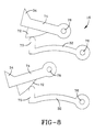
- Fig. 8 the operation of the pawl and pawl actuating lever from the third aspect of the invention is illustrated.
- the pawl 16 is formed in two parts.
- the cap 32 which extends over the mass 14 has a pawl actuating tip 70 which engages a ramped surface 72 on the underside of a pawl 74.
- the cap 32 is pivotally mounted at pivot point 76 to the support 12 and the pawl 74 is pivotally mounted at pivot point 78 to the retractor.
- the pawl 74 further includes a pawl tooth 34, similar to that shown in previous embodiments.
- pawl actuating tip 70 engages the ramped surface 72 towards a right hand end thereof which means that the pawl tip 34 will be moved away from the ratchet 36 and will be arranged lower relative to the ratchet 36 than when the pawl actuating tip 17 engages the left hand end of the ramped surface 72.
- relative lateral movement between the pawl 74 and the cap 36 will result in adjustment of the initial position of the pawl tooth 34 and thus adjustment of the size of the gap between the tooth 34 and the teeth of the ratchet 36.
- Fig. 8 shows the pawl 74 moving and the cap 36 remaining stationary it will be appreciated that the pawl could be held fixed and the cap moved relative to it. Indeed that latter arrangement is preferred.
- Fig. 9 part of the vehicle sensor for use in a retractor in accordance with the fourth aspect of the invention is illustrated.
- the sensor 10 is substantially similar to that illustrated in Fig. 1 and parts corresponding to parts in Figs. 1 and 2 carry the same reference numerals.
- Fig. 9 the majority of the sensor 10 is omitted for clarity and the main part of interest is the pawl 16 and its relation to the inertia mass 14.
- the pawl 16 comprises a cap 32 and a pawl tooth 34.
- the cap 32 has a ramped portion 80 on the lower surface thereof which rests upon the mass 14.
- the pawl 16 is pivotal about an axis A defined by a shaft 82 which extends through a bore 84 in the pawl 16.
- the shaft 82 comprises a cylindrical body 86 with spigots 88, 90 extending from opposite ends of the body 86, offset from the axis A.
- the spigots 88, 90 are co-axial on axis B.
- the spigots 88, 90 are received in apertures formed in the upper part of the end wall 26 of the support 12 (not shown).
- rotation of the spigots 88, 90 about the axis B will cause the cylindrical body 86 to rotate about the axis B.
- axis B is offset from the centre of the cylindrical body 86 the rotation will tend to move the pawl 16 from side to side.
- the lateral position of the pawl 16 can be altered so that the mass 14 engages the ramped surface 80 on the underside of the pawl 16 at different points so as to effect adjustment of the initial position of the pawl tooth 34 relative to the ratchet 36.
- the first aspect of the invention provides a method whereby the initial position of the pawl tooth can be altered over quite large distances whereas the fourth aspect of the invention provides a method of altering the initial position of the pawl tooth over smaller distances.
- Combination of the two systems can be provide a method whereby initial adjustment is effected over a large distance and then a finer final adjustment is made using the fourth aspect arrangement.
- the arrangement set out in the second aspect of the invention may be incorporated so as to allow continual adjustment of the pawl tooth gap during operation of the retractor.
Landscapes
- Engineering & Computer Science (AREA)
- Mechanical Engineering (AREA)
- Automotive Seat Belt Assembly (AREA)
Abstract
Description
Claims (11)
- A seat belt retractor comprising a frame, a spool rotatably mounted to the frame, a spool locking device for locking the spool to prevent rotation thereof, actuating means for actuating the spool locking device comprising a support carrying a mass and a pawl, the mass being arranged to move from an initial position to an actuating position to actuate the pawl into engagement with a ratchet on the spool whereby engagement of the pawl with the ratchet actuates the spool locking device, the support being arranged to pivot so as to adjust the distance between the pawl and the ratchet.
- A seat belt retractor according to claim 1 in which the pawl is arranged to one side of the support and the support is pivotable about a longitudinal axis thereof, which axis is spaced from the pawl.
- A seat belt retractor according to claim 2 in which the support preferably comprises a base having a recess and two end walls upstanding from opposite edges of the base, the mass being received in the recess and the pawl being arranged over the mass, pivotally mounted to an upper part of one end wall.
- A seat belt retractor according to claim 3 in which the support includes respective pivot members extending from each end wall to enable the support to be pivotally mounted to the frame.
- A seat belt retractor according to claim 1 in which the support is pivotable about a transverse axis, which axis is located toward one end of the support, the pawl being spaced from the axis.
- A seat belt retractor comprising a frame, a spool rotatably mounted to the frame, a spool locking device for locking the spool to prevent rotation thereof, actuating means for actuating the spool locking device comprising a support carrying a mass and a pawl, the mass being arranged to move from an initial position to an actuating position to actuate the pawl into engagement with a ratchet on the spool whereby engagement of the pawl with the ratchet actuates the spool locking device, the spool having a cam formation with a circular cam periphery arranged substantially coaxially therewith, the support having a cam follower, the support being mounted movably relative to the spool in response to movement of the cam follower.
- A seat belt retractor according to claim 7 in which the support is pivotably mounted to the frame so that movement of the cam follower causes the support to pivot so as to effect automatic tip gap adjustment.
- A seat belt retractor comprising a frame, a spool rotably mounted to the frame, a spool locking device for locking the spool to prevent rotation thereof, actuating means for actuating the spool locking device comprising a support carrying a mass and a pawl, the mass being arranged to move from an initial position to an actuating position to actuate the pawl into engagement with a ratchet on the spool whereby engagement of the pawl with the ratchet actuates the spool locking device, the actuating means comprising a pawl, actuating lever pivotally mounted to the support and arranged between the mass and the pawl, the pawl including a cam surface, the pawl actuating lever along the cam surface adjusts the distance between the pawl and the ratchet.
- A seat belt retractor according to claim 8 in which the movement of the pawl actuating lever along the cam surface is effected by means of a movement mechanism comprising a pivot pin which pivotally mounts the pawl actuating lever and a pivot peg extending from the pivot pin, parallel with and offset from the axis thereof, and received in the support, whereby rotation of the pivot peg effects movement of the pawl actuating lever along the cam surface.
- A seat belt retractor comprising a frame, a spool rotatably mounted to the frame, a spool locking device for locking the spool to prevent rotation thereof, actuating means for actuating the spool locking device comprising a support carrying a mass and a pawl, the mass being arranged to move from an initial position to an actuating position to actuate the pawl into engagement with a ratchet on the spool whereby engagement of the pawl with the ratchet actuates the spool locking device, the mass engaging the underside of the pawl, the underside of the pawl having a cam surface thereon whereby movement of the mass relative to the pawl along the cam surface effects adjustment of the distance between the pawl and the ratchet.
- A seat belt retractor according to claim 10 in which movement of the pawl is effected by a movement mechanism which comprises a pivot pin which pivotally mounts the pawl and a pivot peg extending from the pivot pin, parallel with and offset from the axis thereof, and received in the support, whereby rotation of the pivot peg effects relative movement of the pawl and mass.
Applications Claiming Priority (4)
| Application Number | Priority Date | Filing Date | Title |
|---|---|---|---|
| GB9908976 | 1999-04-21 | ||
| GBGB9908976.5A GB9908976D0 (en) | 1999-04-21 | 1999-04-21 | A seat belt retractor |
| GB0009774A GB2349120B (en) | 1999-04-21 | 2000-04-20 | A seat belt retractor |
| GB0009774 | 2000-04-20 |
Publications (3)
| Publication Number | Publication Date |
|---|---|
| EP1048536A2 true EP1048536A2 (en) | 2000-11-02 |
| EP1048536A3 EP1048536A3 (en) | 2001-08-01 |
| EP1048536B1 EP1048536B1 (en) | 2005-02-09 |
Family
ID=26244140
Family Applications (1)
| Application Number | Title | Priority Date | Filing Date |
|---|---|---|---|
| EP20000303424 Expired - Lifetime EP1048536B1 (en) | 1999-04-21 | 2000-04-25 | A seat belt retractor |
Country Status (2)
| Country | Link |
|---|---|
| EP (1) | EP1048536B1 (en) |
| DE (1) | DE60017970T2 (en) |
Cited By (5)
| Publication number | Priority date | Publication date | Assignee | Title |
|---|---|---|---|---|
| CN104153659A (en) * | 2014-07-14 | 2014-11-19 | 中国核电工程有限公司 | A personnel gate interlocking mechanism |
| CN104386017A (en) * | 2014-11-27 | 2015-03-04 | 夏爱棠 | Control device for automobile safety belt |
| WO2015038608A1 (en) * | 2013-09-13 | 2015-03-19 | Key Safety Systems Inc. | Retractor with gimbaled vehicle sensor |
| CN107702914A (en) * | 2017-11-20 | 2018-02-16 | 何启全 | A kind of wireless detection device for the locking of recreation facility safety Crowbar Pressing |
| JP2021049856A (en) * | 2019-09-25 | 2021-04-01 | 株式会社東海理化電機製作所 | Webbing winding device |
Family Cites Families (3)
| Publication number | Priority date | Publication date | Assignee | Title |
|---|---|---|---|---|
| US3990651A (en) * | 1974-11-18 | 1976-11-09 | Irvin Industries, Inc. | Safety belt retractor locking device |
| GB1528184A (en) * | 1976-09-15 | 1978-10-11 | Britax Ltd | Safety belt reel with adjustable locking mechanism |
| GB2328184B (en) * | 1997-08-12 | 2001-10-17 | Alliedsignal Ltd | Vehicle sensor |
-
2000
- 2000-04-25 EP EP20000303424 patent/EP1048536B1/en not_active Expired - Lifetime
- 2000-04-25 DE DE2000617970 patent/DE60017970T2/en not_active Expired - Fee Related
Cited By (9)
| Publication number | Priority date | Publication date | Assignee | Title |
|---|---|---|---|---|
| WO2015038608A1 (en) * | 2013-09-13 | 2015-03-19 | Key Safety Systems Inc. | Retractor with gimbaled vehicle sensor |
| CN104153659A (en) * | 2014-07-14 | 2014-11-19 | 中国核电工程有限公司 | A personnel gate interlocking mechanism |
| CN104153659B (en) * | 2014-07-14 | 2016-08-24 | 中国核电工程有限公司 | Personnel gate interlocking mechanism |
| CN104386017A (en) * | 2014-11-27 | 2015-03-04 | 夏爱棠 | Control device for automobile safety belt |
| CN107702914A (en) * | 2017-11-20 | 2018-02-16 | 何启全 | A kind of wireless detection device for the locking of recreation facility safety Crowbar Pressing |
| CN107702914B (en) * | 2017-11-20 | 2024-04-09 | 何启全 | Wireless detection device for locking safety pressing bar of amusement equipment |
| JP2021049856A (en) * | 2019-09-25 | 2021-04-01 | 株式会社東海理化電機製作所 | Webbing winding device |
| WO2021060392A1 (en) * | 2019-09-25 | 2021-04-01 | 株式会社東海理化電機製作所 | Webbing winding device |
| JP7184290B2 (en) | 2019-09-25 | 2022-12-06 | 株式会社東海理化電機製作所 | Webbing take-up device |
Also Published As
| Publication number | Publication date |
|---|---|
| EP1048536A3 (en) | 2001-08-01 |
| DE60017970D1 (en) | 2005-03-17 |
| DE60017970T2 (en) | 2006-04-06 |
| EP1048536B1 (en) | 2005-02-09 |
Similar Documents
| Publication | Publication Date | Title |
|---|---|---|
| EP0961712B1 (en) | Inertia locking device for a vehicle seat adjustment mechanism | |
| EP1247688B1 (en) | Child car seat | |
| USRE32790E (en) | Inertially locked hinge for motor vehicle seat | |
| JP2750101B2 (en) | Seat belt web retractor | |
| US6299093B1 (en) | Sensor for a seat belt retractor | |
| US6585324B2 (en) | Activation device for a vehicle seat adjuster | |
| GB2349120A (en) | Actuation means for a seat belt retractor | |
| US20060138845A1 (en) | Armest height-adjusting device | |
| EP0839686A2 (en) | Seat reclining device. | |
| US4928374A (en) | Method of vehicle seat latch | |
| EP1048536A2 (en) | A seat belt retractor | |
| US4846526A (en) | Apparatus and method of vehicle seat latch | |
| US6631865B2 (en) | Seat belt retractor | |
| JP3929577B2 (en) | Body acceleration sensor for seat belt | |
| JPH08133011A (en) | Webbing winding device | |
| US4164335A (en) | Automatic locking retractor with lock-up delay | |
| GB2309883A (en) | Seat belt retractor engagement mechanism | |
| JP2653766B2 (en) | Inertial sensor for vehicle response triggering of belt retractor lock mechanism | |
| KR200207987Y1 (en) | A head rest for vehicles | |
| US6257375B1 (en) | Brake-tuning device of a bicycle | |
| JP3957111B2 (en) | Acceleration sensor | |
| US4069987A (en) | Inertia locking seat belt retractor | |
| US4065069A (en) | Emergency locking retractor | |
| US20080230644A1 (en) | Vehicle sensitive seat belt retractor control with suppressed Z-axis sensitivity | |
| EP0976606B1 (en) | Seat reclining system |
Legal Events
| Date | Code | Title | Description |
|---|---|---|---|
| PUAI | Public reference made under article 153(3) epc to a published international application that has entered the european phase |
Free format text: ORIGINAL CODE: 0009012 |
|
| AK | Designated contracting states |
Kind code of ref document: A2 Designated state(s): DE ES FR GB IT |
|
| AX | Request for extension of the european patent |
Free format text: AL;LT;LV;MK;RO;SI |
|
| PUAL | Search report despatched |
Free format text: ORIGINAL CODE: 0009013 |
|
| AK | Designated contracting states |
Kind code of ref document: A3 Designated state(s): AT BE CH CY DE DK ES FI FR GB GR IE IT LI LU MC NL PT SE |
|
| AX | Request for extension of the european patent |
Free format text: AL;LT;LV;MK;RO;SI |
|
| RIC1 | Information provided on ipc code assigned before grant |
Free format text: 7B 60R 22/405 A, 7B 60R 22/40 B |
|
| 17P | Request for examination filed |
Effective date: 20010830 |
|
| 17Q | First examination report despatched |
Effective date: 20011213 |
|
| AKX | Designation fees paid |
Free format text: DE ES FR GB IT |
|
| GRAP | Despatch of communication of intention to grant a patent |
Free format text: ORIGINAL CODE: EPIDOSNIGR1 |
|
| RAP1 | Party data changed (applicant data changed or rights of an application transferred) |
Owner name: KEY SAFETY SYSTEMS, INC. |
|
| GRAS | Grant fee paid |
Free format text: ORIGINAL CODE: EPIDOSNIGR3 |
|
| GRAA | (expected) grant |
Free format text: ORIGINAL CODE: 0009210 |
|
| AK | Designated contracting states |
Kind code of ref document: B1 Designated state(s): DE ES FR GB IT |
|
| PG25 | Lapsed in a contracting state [announced via postgrant information from national office to epo] |
Ref country code: ES Free format text: LAPSE BECAUSE OF FAILURE TO SUBMIT A TRANSLATION OF THE DESCRIPTION OR TO PAY THE FEE WITHIN THE PRESCRIBED TIME-LIMIT Effective date: 20050209 |
|
| REG | Reference to a national code |
Ref country code: GB Ref legal event code: FG4D |
|
| REF | Corresponds to: |
Ref document number: 60017970 Country of ref document: DE Date of ref document: 20050317 Kind code of ref document: P |
|
| PLBE | No opposition filed within time limit |
Free format text: ORIGINAL CODE: 0009261 |
|
| STAA | Information on the status of an ep patent application or granted ep patent |
Free format text: STATUS: NO OPPOSITION FILED WITHIN TIME LIMIT |
|
| 26N | No opposition filed |
Effective date: 20051110 |
|
| ET | Fr: translation filed | ||
| PGFP | Annual fee paid to national office [announced via postgrant information from national office to epo] |
Ref country code: FR Payment date: 20060403 Year of fee payment: 7 |
|
| PGFP | Annual fee paid to national office [announced via postgrant information from national office to epo] |
Ref country code: DE Payment date: 20060428 Year of fee payment: 7 |
|
| GBPC | Gb: european patent ceased through non-payment of renewal fee |
Effective date: 20070425 |
|
| PGFP | Annual fee paid to national office [announced via postgrant information from national office to epo] |
Ref country code: IT Payment date: 20070616 Year of fee payment: 8 |
|
| PG25 | Lapsed in a contracting state [announced via postgrant information from national office to epo] |
Ref country code: DE Free format text: LAPSE BECAUSE OF NON-PAYMENT OF DUE FEES Effective date: 20071101 |
|
| PG25 | Lapsed in a contracting state [announced via postgrant information from national office to epo] |
Ref country code: GB Free format text: LAPSE BECAUSE OF NON-PAYMENT OF DUE FEES Effective date: 20070425 |
|
| PG25 | Lapsed in a contracting state [announced via postgrant information from national office to epo] |
Ref country code: FR Free format text: LAPSE BECAUSE OF NON-PAYMENT OF DUE FEES Effective date: 20070430 |
|
| PGFP | Annual fee paid to national office [announced via postgrant information from national office to epo] |
Ref country code: GB Payment date: 20060314 Year of fee payment: 7 |
|
| PG25 | Lapsed in a contracting state [announced via postgrant information from national office to epo] |
Ref country code: IT Free format text: LAPSE BECAUSE OF NON-PAYMENT OF DUE FEES Effective date: 20080425 |