EP1048433A2 - Kneading degree adjusting device for twin screw extruder - Google Patents
Kneading degree adjusting device for twin screw extruder Download PDFInfo
- Publication number
- EP1048433A2 EP1048433A2 EP00108993A EP00108993A EP1048433A2 EP 1048433 A2 EP1048433 A2 EP 1048433A2 EP 00108993 A EP00108993 A EP 00108993A EP 00108993 A EP00108993 A EP 00108993A EP 1048433 A2 EP1048433 A2 EP 1048433A2
- Authority
- EP
- European Patent Office
- Prior art keywords
- opening degree
- face
- gate
- semicircular
- semicircular face
- Prior art date
- Legal status (The legal status is an assumption and is not a legal conclusion. Google has not performed a legal analysis and makes no representation as to the accuracy of the status listed.)
- Granted
Links
Images



Classifications
-
- B—PERFORMING OPERATIONS; TRANSPORTING
- B29—WORKING OF PLASTICS; WORKING OF SUBSTANCES IN A PLASTIC STATE IN GENERAL
- B29B—PREPARATION OR PRETREATMENT OF THE MATERIAL TO BE SHAPED; MAKING GRANULES OR PREFORMS; RECOVERY OF PLASTICS OR OTHER CONSTITUENTS OF WASTE MATERIAL CONTAINING PLASTICS
- B29B7/00—Mixing; Kneading
- B29B7/30—Mixing; Kneading continuous, with mechanical mixing or kneading devices
- B29B7/34—Mixing; Kneading continuous, with mechanical mixing or kneading devices with movable mixing or kneading devices
- B29B7/38—Mixing; Kneading continuous, with mechanical mixing or kneading devices with movable mixing or kneading devices rotary
- B29B7/46—Mixing; Kneading continuous, with mechanical mixing or kneading devices with movable mixing or kneading devices rotary with more than one shaft
- B29B7/48—Mixing; Kneading continuous, with mechanical mixing or kneading devices with movable mixing or kneading devices rotary with more than one shaft with intermeshing devices, e.g. screws
- B29B7/488—Parts, e.g. casings, sealings; Accessories, e.g. flow controlling or throttling devices
-
- B—PERFORMING OPERATIONS; TRANSPORTING
- B29—WORKING OF PLASTICS; WORKING OF SUBSTANCES IN A PLASTIC STATE IN GENERAL
- B29B—PREPARATION OR PRETREATMENT OF THE MATERIAL TO BE SHAPED; MAKING GRANULES OR PREFORMS; RECOVERY OF PLASTICS OR OTHER CONSTITUENTS OF WASTE MATERIAL CONTAINING PLASTICS
- B29B7/00—Mixing; Kneading
- B29B7/30—Mixing; Kneading continuous, with mechanical mixing or kneading devices
- B29B7/34—Mixing; Kneading continuous, with mechanical mixing or kneading devices with movable mixing or kneading devices
- B29B7/38—Mixing; Kneading continuous, with mechanical mixing or kneading devices with movable mixing or kneading devices rotary
- B29B7/46—Mixing; Kneading continuous, with mechanical mixing or kneading devices with movable mixing or kneading devices rotary with more than one shaft
- B29B7/465—Mixing; Kneading continuous, with mechanical mixing or kneading devices with movable mixing or kneading devices rotary with more than one shaft each shaft comprising rotor parts of the Banbury type in addition to screw parts
-
- B—PERFORMING OPERATIONS; TRANSPORTING
- B29—WORKING OF PLASTICS; WORKING OF SUBSTANCES IN A PLASTIC STATE IN GENERAL
- B29C—SHAPING OR JOINING OF PLASTICS; SHAPING OF MATERIAL IN A PLASTIC STATE, NOT OTHERWISE PROVIDED FOR; AFTER-TREATMENT OF THE SHAPED PRODUCTS, e.g. REPAIRING
- B29C48/00—Extrusion moulding, i.e. expressing the moulding material through a die or nozzle which imparts the desired form; Apparatus therefor
- B29C48/25—Component parts, details or accessories; Auxiliary operations
- B29C48/36—Means for plasticising or homogenising the moulding material or forcing it through the nozzle or die
- B29C48/395—Means for plasticising or homogenising the moulding material or forcing it through the nozzle or die using screws surrounded by a cooperating barrel, e.g. single screw extruders
- B29C48/40—Means for plasticising or homogenising the moulding material or forcing it through the nozzle or die using screws surrounded by a cooperating barrel, e.g. single screw extruders using two or more parallel screws or at least two parallel non-intermeshing screws, e.g. twin screw extruders
-
- B—PERFORMING OPERATIONS; TRANSPORTING
- B29—WORKING OF PLASTICS; WORKING OF SUBSTANCES IN A PLASTIC STATE IN GENERAL
- B29C—SHAPING OR JOINING OF PLASTICS; SHAPING OF MATERIAL IN A PLASTIC STATE, NOT OTHERWISE PROVIDED FOR; AFTER-TREATMENT OF THE SHAPED PRODUCTS, e.g. REPAIRING
- B29C48/00—Extrusion moulding, i.e. expressing the moulding material through a die or nozzle which imparts the desired form; Apparatus therefor
- B29C48/25—Component parts, details or accessories; Auxiliary operations
- B29C48/36—Means for plasticising or homogenising the moulding material or forcing it through the nozzle or die
- B29C48/395—Means for plasticising or homogenising the moulding material or forcing it through the nozzle or die using screws surrounded by a cooperating barrel, e.g. single screw extruders
- B29C48/40—Means for plasticising or homogenising the moulding material or forcing it through the nozzle or die using screws surrounded by a cooperating barrel, e.g. single screw extruders using two or more parallel screws or at least two parallel non-intermeshing screws, e.g. twin screw extruders
- B29C48/404—Means for plasticising or homogenising the moulding material or forcing it through the nozzle or die using screws surrounded by a cooperating barrel, e.g. single screw extruders using two or more parallel screws or at least two parallel non-intermeshing screws, e.g. twin screw extruders the screws having non-intermeshing parts
-
- B—PERFORMING OPERATIONS; TRANSPORTING
- B29—WORKING OF PLASTICS; WORKING OF SUBSTANCES IN A PLASTIC STATE IN GENERAL
- B29C—SHAPING OR JOINING OF PLASTICS; SHAPING OF MATERIAL IN A PLASTIC STATE, NOT OTHERWISE PROVIDED FOR; AFTER-TREATMENT OF THE SHAPED PRODUCTS, e.g. REPAIRING
- B29C48/00—Extrusion moulding, i.e. expressing the moulding material through a die or nozzle which imparts the desired form; Apparatus therefor
- B29C48/25—Component parts, details or accessories; Auxiliary operations
- B29C48/36—Means for plasticising or homogenising the moulding material or forcing it through the nozzle or die
- B29C48/50—Details of extruders
- B29C48/505—Screws
- B29C48/575—Screws provided with elements of a generally circular cross-section for shearing the melt, i.e. shear-ring elements
-
- B—PERFORMING OPERATIONS; TRANSPORTING
- B29—WORKING OF PLASTICS; WORKING OF SUBSTANCES IN A PLASTIC STATE IN GENERAL
- B29C—SHAPING OR JOINING OF PLASTICS; SHAPING OF MATERIAL IN A PLASTIC STATE, NOT OTHERWISE PROVIDED FOR; AFTER-TREATMENT OF THE SHAPED PRODUCTS, e.g. REPAIRING
- B29C48/00—Extrusion moulding, i.e. expressing the moulding material through a die or nozzle which imparts the desired form; Apparatus therefor
- B29C48/25—Component parts, details or accessories; Auxiliary operations
- B29C48/36—Means for plasticising or homogenising the moulding material or forcing it through the nozzle or die
- B29C48/50—Details of extruders
- B29C48/68—Barrels or cylinders
- B29C48/685—Barrels or cylinders characterised by their inner surfaces, e.g. having grooves, projections or threads
- B29C48/686—Barrels or cylinders characterised by their inner surfaces, e.g. having grooves, projections or threads having grooves or cavities
-
- B—PERFORMING OPERATIONS; TRANSPORTING
- B29—WORKING OF PLASTICS; WORKING OF SUBSTANCES IN A PLASTIC STATE IN GENERAL
- B29C—SHAPING OR JOINING OF PLASTICS; SHAPING OF MATERIAL IN A PLASTIC STATE, NOT OTHERWISE PROVIDED FOR; AFTER-TREATMENT OF THE SHAPED PRODUCTS, e.g. REPAIRING
- B29C48/00—Extrusion moulding, i.e. expressing the moulding material through a die or nozzle which imparts the desired form; Apparatus therefor
- B29C48/03—Extrusion moulding, i.e. expressing the moulding material through a die or nozzle which imparts the desired form; Apparatus therefor characterised by the shape of the extruded material at extrusion
-
- B—PERFORMING OPERATIONS; TRANSPORTING
- B29—WORKING OF PLASTICS; WORKING OF SUBSTANCES IN A PLASTIC STATE IN GENERAL
- B29C—SHAPING OR JOINING OF PLASTICS; SHAPING OF MATERIAL IN A PLASTIC STATE, NOT OTHERWISE PROVIDED FOR; AFTER-TREATMENT OF THE SHAPED PRODUCTS, e.g. REPAIRING
- B29C48/00—Extrusion moulding, i.e. expressing the moulding material through a die or nozzle which imparts the desired form; Apparatus therefor
- B29C48/25—Component parts, details or accessories; Auxiliary operations
- B29C48/255—Flow control means, e.g. valves
- B29C48/2552—Flow control means, e.g. valves provided in the feeding, melting, plasticising or pumping zone, e.g. screw, barrel, gear-pump or ram
-
- B—PERFORMING OPERATIONS; TRANSPORTING
- B29—WORKING OF PLASTICS; WORKING OF SUBSTANCES IN A PLASTIC STATE IN GENERAL
- B29C—SHAPING OR JOINING OF PLASTICS; SHAPING OF MATERIAL IN A PLASTIC STATE, NOT OTHERWISE PROVIDED FOR; AFTER-TREATMENT OF THE SHAPED PRODUCTS, e.g. REPAIRING
- B29C48/00—Extrusion moulding, i.e. expressing the moulding material through a die or nozzle which imparts the desired form; Apparatus therefor
- B29C48/25—Component parts, details or accessories; Auxiliary operations
- B29C48/268—Throttling of the flow, e.g. for cooperating with plasticising elements or for degassing
Definitions
- the present invention relates to a kneading degree adjusting device for a twin extruder.
- Fig. 6 shows one example of kneading degree adjusting devices in a conventional twin extruder.
- This kneading degree adjusting device in the twin extruder comprises a cylinder 101 and two screws 102 which are rotatably provided in the cylinder 101.
- a pair of gate valves 103a, 103b provided at a downstream side of a kneading part B so as to be movable perpendicularly to an axial direction (upward and downward in the drawings) are brought closer to or separated from each other by means of hydraulic cylinders 106a, 106b, whereby gaps formed between faces 102a at the root of a flight of the screws 102 and semicircular faces 104a, 104b formed at the tip ends of the gate valves 103a, 103b are changed in size, thereby to vary the kneading degree (Examined Japanese Utility Model Publication Hei.7-56185.
- a sectional shape of the opening degree variable channel varies from a substantially annular shape to a substantially oval shape, and the gaps between the semicircular faces of a pair of the gate valves and the faces of the screws at the root of the flight are subjected to a greater change in a vertical direction than in a lateral direction.
- an unmolten material having high viscosity is allowed to short-pass the larger gaps in an upper and a lower parts, and thus a filling degree of the material in the kneading part upstream of the gate valves will become unstable. Therefore, a uniform kneading efficiency cannot be obtained.
- opening degree of the opening degree variable channel is changed by moving a pair of the gate valves perpendicularly to the axial direction of the cylinder, not only opening and closing times of the channels will be longer but also the structure will become complicated.
- the invention has been made in view of the above described problems that the conventional art has had, and aims to realize a kneading degree adjusting device for a twin extruder in which the filling degree of the material can be stabilized and the opening and closing motions of the channels can be rapidly conducted.
- a kneading degree adjusting device for a twin extruder which comprises a cylinder and two screws rotatably provided in the cylinder, wherein at least a feeding part, a kneading part, a gate part and a discharging part are provided in order from an upstream side to a down stream side, characterized in that the device includes an opening degree variable channel forming part respectively provided in the screws at a position corresponding to the gate part, each of the opening degree variable channel forming parts having an outer diameter which is equal to or slightly larger than a diameter of the screw at the root of a flight thereof, an upper guide bore and a lower guide bore provided in the cylinder above and below the screws at a position corresponding to the gate part so as to extend in a radial direction, gate rods rotatably contained in the upper guide bore and the lower guide bore respectively, each of the gate rods being provided with opening degree changing recesses in a form of
- a boundary part between the first semicircular face and the second semicircular face may include a curved face.
- Fig. 1 is an explanatory view of a kneading degree adjusting device for a twin extruder according to one embodiment of the invention.
- Fig. 2 shows a gate rod in the kneading degree adjusting device for the twin extruder in Fig. 1, wherein (A) is a front view and (B) is a sectional view taken along a line A-A in (A).
- FIG. 3 shows opening degree variable channels in a gate part of the kneading degree adjusting device for the twin extruder in Fig. 1 in a fully opened state, wherein (A) is a schematic enlarged view partly in section, (B) is a schematic sectional view taken along a line B-B in (A).
- Fig. 4 shows the opening degree variable channels in the gate part of the kneading degree adjusting device for the twin extruder in Fig. 1 in a fully closed state, wherein (A) is a schematic enlarged view partly in section, (B) is a schematic sectional view taken along a line C-C in (A).
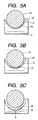
- Fig. 5 shows shapes of the opening degree variable channel in the kneading degree adjusting device for the twin extruder according to the invention as seen in an axial direction, wherein (A) is an explanatory view of the fully closed state, (B) is an explanatory view of a half opened state, and (C) is an explanatory view of the fully opened state.
- Fig. 6 shows a conventional kneading degree adjusting device for the twin extruder, wherein (A) is a sectional view, (B) is an enlarged view of the essential portion partly in section, and (C) is a sectional view taken along a line A-A.
- the kneading degree adjusting device for the twin extruder comprises a cylinder 2 supported on a base 1, two screws 3 rotatably provided in the cylinder 2, and non-shown rotation actuating means for rotating the two screws 3 in a same direction or in different directions, and consists of a feeding part, a kneading part A, a gate part B, a vent part having a vent port 8 and a discharging part in order from a supply port 6 formed at one end of the cylinder 2 toward a discharge port 9 formed at the other end.
- Each of the screws 3 is provided with a rotor 5 at a position corresponding to the kneading part A, and at a position corresponding to the gate part B, an opening degree variable channel forming part 14 in a columnar shape having an outer diameter which is equal to or slightly larger than a diameter of the screw 3 at the root of a flight.
- the entire area of the screw 3 except the kneading part A and the gate part B is provided with flights 4.
- the cylinder 2 is provided at a position corresponding to the gate part B with an upper guide bore 10a and a lower guide bore lOb respectively above and below the screws 3 so as to extend in a direction perpendicular to the axial direction of the cylinder and open largely in an inner wall of the cylinder.
- lOb Into both the guide bores 10a, lOb are rotatably inserted gate rods 7 which will be described later.
- each of the gate rods 7 may be projected outwardly from an outer wall of the cylinder 2 and connected to non-shown rotation actuating means so as to perform a positive and a reverse rotations at determined rotation angles.
- each of the gate rods 7 is formed with opening degree changing recesses 11 in a form of an opencut adjacent to each other in its axial direction in order to constitute opening degree variable channels S in an annular shape in combination with outer peripheral faces of the opening degree variable channel forming parts 14 of the screws 3.
- Each of the opening degree changing recesses 11 consists of a first semicircular face 12 having an inner diameter which is equal to or slightly larger than an inner wall face 2a of the cylinder 2, and a second semicircular face 13 having such a shape that an upstream side end of the first semicircular face 12 is diagonally cut and outwardly slanted at a determined angle a from the first semicircular face 12.
- the second semicircular face 13 has an inner diameter which is equal to or slightly larger than an outer diameter of the opening degree variable channel forming part 14 of the screw 3.
- the second semicircular face 13 is formed in a shape that is tapered (cut) from the first semicircular face 12 at its upstream side end.
- the second semicircular face 13 is not limited to such the shape but may be formed in a shape that is tapered (cut) from the first semicircular face 12 at its downstream side end. It is to be noted that in case where the second semicircular face 13 is formed in the shape that is tapered (cut) from the first semicircular face 12 at its downstream side end, arrangement of the gate rods 7 in an axial direction of the cylinder must be set in such a manner that a boundary part between both the faces may confront the opening degree variable channel forming part 14 of the screw 3.
- boundary part between the first semicircular face 12 and the second semicircular face 13 is not limited to an angled shape as in this embodiment, but may be formed as a curved face.
- Fig. 3 shows the opening degree variable channels S in a fully opened state.
- the gate rods 7 inserted through the upper guide bore 10a and the lower guide bore 10b axially symmetrically are rotated respectively to the positions at which the first semicircular face 12 and the outer peripheral face of the opening degree variable channel forming part 14 are substantially in parallel, and the opening degree of the variable channels S will become maximum.
- the shape of the opening degree variable channel S is a perfect ring as seen from the axial direction.
- Fig. 4 shows the opening degree variable channels S in a fully closed state.
- the gate rods 7 inserted through the upper guide bore 10a and the lower guide bore 10b axially symmetrically are rotated respectively to the positions at which the second semicircular face 13 is in abutment against the outer peripheral face of the opening degree variable channel forming part 14 in each of the screws 3, and the opening degree of the opening degree variable channels S will become minimum.
- the shape of the opening degree variable channel S as seen from the axial direction is such that slight gaps are formed by the first semicircular faces 12 at both sides of the axial core.
- Fig. 5 shows the shape of the opening degree variable channel S in a fully closed, in a half closed, and in a fully opened state as seen in an axial direction.
- the shape of the opening degree variable channel S is substantially annular as seen in the axial direction.
- the invention can be applied not only to the kneading machine comprising the two shafts having the same diameter as shown in the above described embodiment, but also to a kneading machine comprising two shafts having different diameters. It is needless to say that the invention is effective not only with a twin extruder of a non-meshed type, but is effective with those of a meshed type and a half-meshed type.
- vent part including the vent port 8 there is provided the vent part including the vent port 8.
- vent part including the vent port there is no need of providing the vent part including the vent port.
- the invention can attain the following effects:
- the shape of the opening degree variable channel as seen in the axial direction is substantially annular in the whole range from the fully opened state to the fully closed state, the filling degree of the material in the kneading part upstream of the gate part will be stabilized, and the uniform kneading efficiency can be obtained.
- the opening degree variable channel can be varied from the fully opened position to the fully closed position by rotating the gate rods at a slight rotation angle, the opening degree can be rapidly changed.
- the gate rods, the guide bores to be provided in the cylinder, etc. can be easily made by machining, the manufacturing cost can be remarkably reduced.
Landscapes
- Engineering & Computer Science (AREA)
- Mechanical Engineering (AREA)
- Extrusion Moulding Of Plastics Or The Like (AREA)
- Processing And Handling Of Plastics And Other Materials For Molding In General (AREA)
Abstract
Description
Claims (2)
- A kneading degree adjusting device for a twin extruder comprising:a cylinder;two screws rotatably provided in said cylinder;at least a feeding part, a kneading part, a gate part and a discharging part provided in order from an upstream side to a downstream side;opening degree variable channel forming parts respectively provided in said screws at a position corresponding to said gate part, each of said opening degree variable channel forming parts having an outer diameter which is equal to or slightly larger than a diameter of said screw at the root of a flight thereof,an upper guide bore and a lower guide bore provided in said cylinder above and below said screws at a position corresponding to said gate part so as to extend in a radial direction,gate rods rotatably contained in said upper guide bore and said lower guide bore respectively, each of said gate rods being provided with opening degree changing recesses in a form of an opencut adjacent to each other in an axial direction of said gate rod so as to constitute opening degree variable channels in an annular shape in combination with outer peripheral faces of said opening degree variable channel forming parts, and that each of said opening degree changing recesses includes a first semicircular face having an inner diameter which is equal to or slightly larger than an inner wall face of said cylinder and a second semicircular face having such a shape that an upstream side end or a downstream side end of said first semicircular face is diagonally cut and outwardly slanted from said first semicircular face, said second semicircular face having an inner diameter which is equal to or slightly larger than said outer peripheral face of said opening degree variable channel forming part.
- A kneading degree adjusting device for a twin extruder as claimed in claim 1, wherein a boundary part between said first semicircular face and said second semicircular face includes a curved face.
Applications Claiming Priority (2)
| Application Number | Priority Date | Filing Date | Title |
|---|---|---|---|
| JP12105999 | 1999-04-28 | ||
| JP11121059A JP3004647B1 (en) | 1999-04-28 | 1999-04-28 | Kneading degree adjusting device for twin screw kneader |
Publications (3)
| Publication Number | Publication Date |
|---|---|
| EP1048433A2 true EP1048433A2 (en) | 2000-11-02 |
| EP1048433A3 EP1048433A3 (en) | 2001-01-31 |
| EP1048433B1 EP1048433B1 (en) | 2002-10-09 |
Family
ID=14801832
Family Applications (1)
| Application Number | Title | Priority Date | Filing Date |
|---|---|---|---|
| EP00108993A Expired - Lifetime EP1048433B1 (en) | 1999-04-28 | 2000-04-27 | Kneading degree adjusting device for twin screw extruder |
Country Status (5)
| Country | Link |
|---|---|
| US (1) | US6238079B1 (en) |
| EP (1) | EP1048433B1 (en) |
| JP (1) | JP3004647B1 (en) |
| CN (1) | CN1142846C (en) |
| DE (1) | DE60000553T2 (en) |
Cited By (5)
| Publication number | Priority date | Publication date | Assignee | Title |
|---|---|---|---|---|
| WO2001062469A1 (en) * | 2000-02-24 | 2001-08-30 | Berstorff Gmbh | Extruder comprising blister mechanism |
| WO2007006327A1 (en) * | 2005-07-12 | 2007-01-18 | Borealis Technology Oy | Counter-rotating twin screw extruder |
| EP2181822A3 (en) * | 2008-10-31 | 2011-04-06 | Kabushiki Kaisha Kobe Seiko Sho (Kobe Steel, Ltd.) | Device and method for adjusting the degree of mixing |
| EP2716426A4 (en) * | 2011-05-30 | 2014-09-10 | Japan Steel Works Ltd | DEVICE FOR PICKING MATERIAL AND METHOD FOR CONTAMINING MATERIAL |
| EP3275612A4 (en) * | 2015-03-27 | 2018-08-15 | The Japan Steel Works, Ltd. | Multi-shaft kneading machine |
Families Citing this family (11)
| Publication number | Priority date | Publication date | Assignee | Title |
|---|---|---|---|---|
| US20030025236A1 (en) * | 2001-08-01 | 2003-02-06 | Xerox Corporation | Toner extruder feed apparatus |
| JP3854298B1 (en) | 2005-07-11 | 2006-12-06 | 株式会社神戸製鋼所 | Kneading degree adjusting device for meshing type twin screw extruder |
| US20070237022A1 (en) * | 2006-04-11 | 2007-10-11 | Wiltz Philip B | Extruder mid-barrel adjustable valve assembly |
| JP2009096004A (en) * | 2007-10-15 | 2009-05-07 | Kobe Steel Ltd | Kneading device |
| JP5005506B2 (en) | 2007-11-02 | 2012-08-22 | 株式会社神戸製鋼所 | Kneading degree adjustment method |
| US7635217B2 (en) * | 2008-01-03 | 2009-12-22 | Wenger Manufacturing, Inc. | Extruder having variable mid-barrel restriction and adjacent high intensity mixing assembly |
| JP5580849B2 (en) | 2012-05-16 | 2014-08-27 | 住友ゴム工業株式会社 | Bead apex rubber forming method and bead apex rubber forming apparatus used therefor |
| JP6719347B2 (en) * | 2016-09-14 | 2020-07-08 | 株式会社日本製鋼所 | Twin screw extruder |
| JP6465091B2 (en) * | 2016-09-30 | 2019-02-06 | トヨタ自動車株式会社 | Biaxial extrusion kneader and method for producing electrode paste using the same |
| JP7578539B2 (en) * | 2021-05-11 | 2024-11-06 | 株式会社日本製鋼所 | Granulator, kneading adjustment mechanism, and resin pellet manufacturing method |
| CN116175927B (en) * | 2023-03-31 | 2025-03-07 | 新印新材料有限公司 | A kind of extruder for carbon powder processing and its using method |
Family Cites Families (18)
| Publication number | Priority date | Publication date | Assignee | Title |
|---|---|---|---|---|
| DE1529811B2 (en) | 1965-06-03 | 1972-06-08 | Barmag Barmer Maschinenfabrik Ag, 5600 Wuppertal | SCREW EXTRUSION PRESS FOR THERMOPLASTIC PLASTICS |
| US3419250A (en) | 1966-10-25 | 1968-12-31 | Read Corp | Continuous mixer discharge control |
| US3981658A (en) | 1972-01-14 | 1976-09-21 | International Basic Economy Corporation | Screw type apparatus for drying moist polymeric materials |
| DE2243039C3 (en) | 1972-09-01 | 1980-08-14 | Werner & Pfleiderer, 7000 Stuttgart | Continuously working screw kneading mixer |
| JPS55139825A (en) * | 1979-03-29 | 1980-11-01 | Kobe Steel Ltd | Continuous type kneader |
| DE2924800C2 (en) * | 1979-06-20 | 1982-08-19 | Werner & Pfleiderer, 7000 Stuttgart | Throttle device for a twin-screw screw machine |
| US4462691A (en) | 1983-01-13 | 1984-07-31 | Uniroyal, Inc. | Mixer/extruder having selectively variable shearing action therein |
| DE3430254A1 (en) | 1984-08-17 | 1986-02-27 | Hoechst Ag, 6230 Frankfurt | SNAIL EXTRUDERS |
| JPH0292516A (en) * | 1988-09-30 | 1990-04-03 | Japan Steel Works Ltd:The | Apparatus for controlling degree of kneading of monoaxial extrusion machine |
| JPH069814B2 (en) | 1988-09-28 | 1994-02-09 | 株式会社日本製鋼所 | Kneading degree adjusting device for twin screw extruder |
| JPH0299305A (en) | 1988-10-07 | 1990-04-11 | Ube Ind Ltd | 2-shaft kneading machine |
| JPH0641136B2 (en) | 1990-05-07 | 1994-06-01 | 株式会社神戸製鋼所 | Kneader gate device |
| JPH0643059B2 (en) | 1990-05-18 | 1994-06-08 | 株式会社神戸製鋼所 | Kneader gate device |
| JP2638258B2 (en) | 1990-05-18 | 1997-08-06 | 株式会社神戸製鋼所 | Gate device of kneading machine |
| DE4115591A1 (en) | 1991-05-14 | 1992-11-19 | Blach Josef A | DEVICE FOR PREPARING AND EXTRUDING MATERIALS |
| DE4223043C2 (en) * | 1992-07-14 | 1994-05-05 | Werner & Pfleiderer | Extruder with throttle punch |
| CH695764A5 (en) | 1992-12-31 | 2006-08-31 | Antogi Ag | Twin-screw extruder. |
| US5909958A (en) | 1997-04-25 | 1999-06-08 | Rauwendaal Extrusion Engineering, Inc. | Screw extruder with independently adjustable groove depth |
-
1999
- 1999-04-28 JP JP11121059A patent/JP3004647B1/en not_active Expired - Fee Related
-
2000
- 2000-04-27 DE DE60000553T patent/DE60000553T2/en not_active Expired - Lifetime
- 2000-04-27 EP EP00108993A patent/EP1048433B1/en not_active Expired - Lifetime
- 2000-04-28 CN CNB001070797A patent/CN1142846C/en not_active Expired - Fee Related
- 2000-04-28 US US09/560,890 patent/US6238079B1/en not_active Expired - Lifetime
Cited By (8)
| Publication number | Priority date | Publication date | Assignee | Title |
|---|---|---|---|---|
| WO2001062469A1 (en) * | 2000-02-24 | 2001-08-30 | Berstorff Gmbh | Extruder comprising blister mechanism |
| US6705753B2 (en) * | 2000-02-24 | 2004-03-16 | Berstoff Gmbh | Extruder comprising blister mechanism |
| WO2007006327A1 (en) * | 2005-07-12 | 2007-01-18 | Borealis Technology Oy | Counter-rotating twin screw extruder |
| US8079747B2 (en) | 2005-07-12 | 2011-12-20 | Borealis Technology Oy | Counter-rotating twin screw extruder |
| EP2181822A3 (en) * | 2008-10-31 | 2011-04-06 | Kabushiki Kaisha Kobe Seiko Sho (Kobe Steel, Ltd.) | Device and method for adjusting the degree of mixing |
| EP2716426A4 (en) * | 2011-05-30 | 2014-09-10 | Japan Steel Works Ltd | DEVICE FOR PICKING MATERIAL AND METHOD FOR CONTAMINING MATERIAL |
| US10576661B2 (en) | 2011-05-30 | 2020-03-03 | The Japan Steel Works, Ltd. | Material kneading apparatus and material kneading method |
| EP3275612A4 (en) * | 2015-03-27 | 2018-08-15 | The Japan Steel Works, Ltd. | Multi-shaft kneading machine |
Also Published As
| Publication number | Publication date |
|---|---|
| CN1271645A (en) | 2000-11-01 |
| JP2000309018A (en) | 2000-11-07 |
| US6238079B1 (en) | 2001-05-29 |
| DE60000553T2 (en) | 2003-02-13 |
| DE60000553D1 (en) | 2002-11-14 |
| EP1048433A3 (en) | 2001-01-31 |
| CN1142846C (en) | 2004-03-24 |
| JP3004647B1 (en) | 2000-01-31 |
| EP1048433B1 (en) | 2002-10-09 |
Similar Documents
| Publication | Publication Date | Title |
|---|---|---|
| EP1048433B1 (en) | Kneading degree adjusting device for twin screw extruder | |
| US5013233A (en) | Distributive mixer device | |
| US5975493A (en) | Process for controlling flow rate of viscous materials including use of a nozzle with changeable opening | |
| DE60110483T2 (en) | Tool for machining | |
| CA1147920A (en) | Method of and apparatus for extruding plastics products | |
| FI100125B (en) | flap valve | |
| DE19918777A1 (en) | Flap valve arrangement as throttles in intake channels in IC engines has power transmission shaft connecting flap valve wings, and injection-molded valve modules | |
| JP2000309017A (en) | Different direction rotating twin screw type extruder | |
| EP1902824B1 (en) | Meshing-type two-axis extruder | |
| US12377595B2 (en) | Extrusion and/or pultrusion device and method | |
| EP2226177A2 (en) | Improved neck block cooling | |
| DE102010050564B4 (en) | Method for producing throttle valves and throttle bodies | |
| KR20050075755A (en) | Mixing device | |
| JPH0756185Y2 (en) | Kneading degree adjusting device for extruder | |
| JPS61241123A (en) | Flow passage resistance adjusting device of double-screw extruder | |
| EP3317072B1 (en) | Injection molding apparatus comprising a fluid channel flow disruption | |
| EP2069124B1 (en) | Transfer element, in particular for a decompression sprue bush and decompression machine nozzle | |
| JP2591893Y2 (en) | Pressure adjusting device for twin screw extruder | |
| JPH05261793A (en) | Apparatus for preparing and continuously extruding material | |
| JP2877790B1 (en) | Kneading degree adjusting device in twin screw extruder | |
| CN107405790B (en) | Multi-axis kneading machine | |
| JP2003071830A (en) | Kneading adjustment device for resin machinery | |
| US5169650A (en) | Calibration unit for extruded plastic material | |
| JPH04257414A (en) | Resin pressure controlling device of twin-screw extruder | |
| JP3544408B2 (en) | Parison diameter die nozzle |
Legal Events
| Date | Code | Title | Description |
|---|---|---|---|
| PUAI | Public reference made under article 153(3) epc to a published international application that has entered the european phase |
Free format text: ORIGINAL CODE: 0009012 |
|
| AK | Designated contracting states |
Kind code of ref document: A2 Designated state(s): DE |
|
| AX | Request for extension of the european patent |
Free format text: AL;LT;LV;MK;RO;SI |
|
| PUAL | Search report despatched |
Free format text: ORIGINAL CODE: 0009013 |
|
| AK | Designated contracting states |
Kind code of ref document: A3 Designated state(s): AT BE CH CY DE DK ES FI FR GB GR IE IT LI LU MC NL PT SE |
|
| AX | Request for extension of the european patent |
Free format text: AL;LT;LV;MK;RO;SI |
|
| RIC1 | Information provided on ipc code assigned before grant |
Free format text: 7B 29C 47/58 A, 7B 29C 47/38 B, 7B 29C 47/40 B, 7B 29B 7/42 B, 7B 29B 7/48 B, 7B 29C 47/76 B |
|
| 17P | Request for examination filed |
Effective date: 20010207 |
|
| 17Q | First examination report despatched |
Effective date: 20010326 |
|
| AKX | Designation fees paid |
Free format text: DE |
|
| GRAG | Despatch of communication of intention to grant |
Free format text: ORIGINAL CODE: EPIDOS AGRA |
|
| GRAG | Despatch of communication of intention to grant |
Free format text: ORIGINAL CODE: EPIDOS AGRA |
|
| GRAH | Despatch of communication of intention to grant a patent |
Free format text: ORIGINAL CODE: EPIDOS IGRA |
|
| GRAH | Despatch of communication of intention to grant a patent |
Free format text: ORIGINAL CODE: EPIDOS IGRA |
|
| GRAA | (expected) grant |
Free format text: ORIGINAL CODE: 0009210 |
|
| AK | Designated contracting states |
Kind code of ref document: B1 Designated state(s): DE |
|
| REF | Corresponds to: |
Ref document number: 60000553 Country of ref document: DE Date of ref document: 20021114 |
|
| PLBE | No opposition filed within time limit |
Free format text: ORIGINAL CODE: 0009261 |
|
| STAA | Information on the status of an ep patent application or granted ep patent |
Free format text: STATUS: NO OPPOSITION FILED WITHIN TIME LIMIT |
|
| 26N | No opposition filed |
Effective date: 20030710 |
|
| REG | Reference to a national code |
Ref country code: DE Ref legal event code: R079 Ref document number: 60000553 Country of ref document: DE Free format text: PREVIOUS MAIN CLASS: B29C0047580000 Ipc: B29C0048500000 |
|
| PGFP | Annual fee paid to national office [announced via postgrant information from national office to epo] |
Ref country code: DE Payment date: 20190416 Year of fee payment: 20 |
|
| REG | Reference to a national code |
Ref country code: DE Ref legal event code: R071 Ref document number: 60000553 Country of ref document: DE |