EP1047257A1 - Système raccordant une installation téléphonique d'abonné au réseau téléphonique commuté et à un réseau numérique à haut débit - Google Patents
Système raccordant une installation téléphonique d'abonné au réseau téléphonique commuté et à un réseau numérique à haut débit Download PDFInfo
- Publication number
- EP1047257A1 EP1047257A1 EP00401083A EP00401083A EP1047257A1 EP 1047257 A1 EP1047257 A1 EP 1047257A1 EP 00401083 A EP00401083 A EP 00401083A EP 00401083 A EP00401083 A EP 00401083A EP 1047257 A1 EP1047257 A1 EP 1047257A1
- Authority
- EP
- European Patent Office
- Prior art keywords
- digital
- signals
- signaling
- analog
- terminal
- Prior art date
- Legal status (The legal status is an assumption and is not a legal conclusion. Google has not performed a legal analysis and makes no representation as to the accuracy of the status listed.)
- Granted
Links
- 230000011664 signaling Effects 0.000 claims abstract description 108
- 238000004891 communication Methods 0.000 claims abstract description 35
- 108091006146 Channels Proteins 0.000 claims description 182
- 230000005540 biological transmission Effects 0.000 claims description 36
- 230000004044 response Effects 0.000 claims description 15
- 101100134875 Arabidopsis thaliana LTA2 gene Proteins 0.000 claims description 10
- 238000009434 installation Methods 0.000 claims description 7
- 239000000284 extract Substances 0.000 claims description 6
- 230000002457 bidirectional effect Effects 0.000 description 7
- 238000012545 processing Methods 0.000 description 7
- 238000006243 chemical reaction Methods 0.000 description 5
- 230000008878 coupling Effects 0.000 description 5
- 238000010168 coupling process Methods 0.000 description 5
- 238000005859 coupling reaction Methods 0.000 description 5
- 238000010586 diagram Methods 0.000 description 4
- 238000001914 filtration Methods 0.000 description 4
- 230000004913 activation Effects 0.000 description 3
- 230000008901 benefit Effects 0.000 description 3
- 238000000605 extraction Methods 0.000 description 3
- 238000013467 fragmentation Methods 0.000 description 3
- 238000006062 fragmentation reaction Methods 0.000 description 3
- 238000003780 insertion Methods 0.000 description 3
- 230000037431 insertion Effects 0.000 description 3
- 238000004458 analytical method Methods 0.000 description 2
- 229940082150 encore Drugs 0.000 description 2
- 238000012423 maintenance Methods 0.000 description 2
- 230000003068 static effect Effects 0.000 description 2
- 238000011282 treatment Methods 0.000 description 2
- 238000012790 confirmation Methods 0.000 description 1
- 208000027744 congestion Diseases 0.000 description 1
- 239000000470 constituent Substances 0.000 description 1
- 238000012217 deletion Methods 0.000 description 1
- 230000037430 deletion Effects 0.000 description 1
- 230000009977 dual effect Effects 0.000 description 1
- 238000005516 engineering process Methods 0.000 description 1
- 239000012634 fragment Substances 0.000 description 1
- 238000000034 method Methods 0.000 description 1
- 239000013307 optical fiber Substances 0.000 description 1
- 230000008569 process Effects 0.000 description 1
- 238000011084 recovery Methods 0.000 description 1
- 238000005070 sampling Methods 0.000 description 1
- 230000001629 suppression Effects 0.000 description 1
- 238000012546 transfer Methods 0.000 description 1
Images



Classifications
-
- H—ELECTRICITY
- H04—ELECTRIC COMMUNICATION TECHNIQUE
- H04L—TRANSMISSION OF DIGITAL INFORMATION, e.g. TELEGRAPHIC COMMUNICATION
- H04L47/00—Traffic control in data switching networks
- H04L47/70—Admission control; Resource allocation
- H04L47/72—Admission control; Resource allocation using reservation actions during connection setup
- H04L47/722—Admission control; Resource allocation using reservation actions during connection setup at the destination endpoint, e.g. reservation of terminal resources or buffer space
-
- H—ELECTRICITY
- H04—ELECTRIC COMMUNICATION TECHNIQUE
- H04L—TRANSMISSION OF DIGITAL INFORMATION, e.g. TELEGRAPHIC COMMUNICATION
- H04L12/00—Data switching networks
- H04L12/28—Data switching networks characterised by path configuration, e.g. LAN [Local Area Networks] or WAN [Wide Area Networks]
- H04L12/2854—Wide area networks, e.g. public data networks
- H04L12/2856—Access arrangements, e.g. Internet access
- H04L12/2869—Operational details of access network equipments
- H04L12/2878—Access multiplexer, e.g. DSLAM
- H04L12/2887—Access multiplexer, e.g. DSLAM characterised by the offered subscriber services
- H04L12/2889—Multiservice, e.g. MSAN
-
- H—ELECTRICITY
- H04—ELECTRIC COMMUNICATION TECHNIQUE
- H04L—TRANSMISSION OF DIGITAL INFORMATION, e.g. TELEGRAPHIC COMMUNICATION
- H04L47/00—Traffic control in data switching networks
- H04L47/70—Admission control; Resource allocation
Definitions
- the present invention relates to a system for connection between a telephone installation subscriber including an analog terminal and a digital terminal on the one hand, and a switch analog telephone and an access node of a high speed digital network.
- the invention relates to the connection of a subscriber telephone system able to communicate with a network terminal dial-up or with any server ISP service provider (Internet Service Provider) of a digital broadband network (Internet).
- ISP service provider Internet Service Provider
- Internet digital broadband network
- Another known solution only remedies the first drawback when the installation telephone is purely digital and is connected by a four-wire digital line supporting a ISDN link with two data channels B and one signaling channel D to an ISDN local exchange of an ISDN integrated services digital network itself connected to the public switched telephone network and to network service provider servers Internet. Besides the last two drawbacks above, the subscriber must abandon his equipment analog telephone to replace it with a completely digital installation.
- the invention aims to provide a system for Telephone subscriber connection obviated to the three aforementioned drawbacks without modifying the infrastructure existing at the local analog switch and using the subscriber phone line existing with two wires.
- the first and second channels following each directions of transmission in the telephone line subscriber i.e. in the pair of wires existing constituting the line, authorizes simultaneously and independently a communication analog telephone, especially speech between the switch and analog terminal and a digital data communication between the node broadband network and digital terminal.
- a communication analog telephone especially speech between the switch and analog terminal and a digital data communication between the node broadband network and digital terminal.
- communication data from digital data does not cross the switch local telephone and so do not clutter the telephone switch by their heavy traffic and sustainable.
- Classic telephone service is not thus degraded by data communications with broadband network (Internet).
- the subscriber can benefit from independent pricing for communications analog telephones and for communications of digital data, and thus benefit from the flat rate pricing for communications with the broadband network.
- the second channels for data communications crossing multiple first equipment of the invention attached to the local switch are sent in a lane high speed multiplex serving the node, such as router or pointer, from the Internet.
- the system connection then includes a third digital equipment common to several firsts EC equipment for demultiplexing a multiplex signal transmitted by the node in several second signals applied respectively to the means for group included in said several first equipment, and to multiplex several fourth digital signals respectively provided by means for separating included in said first equipment in a multiplex signal transmitted to the node.
- the digital link is preferably of the at least two data channels B and one data channel signaling D at lower speed to convey the telephone signaling.
- the first equipment may further include means for detect first signal signals analog telephone transmitted by the switch and a means for inserting first messages digital telephone signaling in a signaling channel respectively in response to first signal signals detected in order to multiplex the two digital channels with the channel signaling to transmit them in the line subscriber telephone to the second device
- the second equipment may further include a means to extract and analyze the first messages signaling channel signaling received from telephone line and means to transmit the first analog signaling signals at analog terminal respectively in response to first signaling messages analyzed.
- the second equipment may further include means for detect second signal signals analog telephones transmitted by the terminal analog, and means for inserting second digital telephone signaling messages in the signaling channel respectively response to second signaling signals detected in order to multiplex the two channels digital with signaling channel for transmit in the subscriber telephone line to the first equipment, and the first equipment can further understand a means for extracting and analyze the second signaling messages of the signaling channel received from the telephone line and means for transmitting the second signals signaling analog to switch respectively in response to the second messages from signaling analyzed.
- the invention adapts to traffic required for communications data between the broadband network and the digital terminal which can be variable and asymmetrical between them.
- the first equipment and one of second equipment and digital terminal can understand ways to dynamically assign one or both digital channels following one and / or the other of the line transmission directions data communication subscriber telephone between the node and the working digital terminal data traffic requested by one and / or the other of the node and digital terminal.
- the system of connection of the invention offers the possibility of transmit voice from the digital terminal to through the broadband network (Internet).
- the second equipment may further include means for convert third analog signals including voice from the digital terminal in digital data messages according to a protocol network broadband network, means for detect third signal signals telephone transmitted by the digital terminal so to convert them into digital messages from signaling according to the network protocol, a means to insert data and signaling according to the network protocol in a signaling channel in order to multiplex them with the two digital channels in the telephone line subscriber to the first device, a means for extract and analyze digital messages from data and signaling according to the protocol signaling channel network received from the line telephone, a way to convert messages digital data according to network protocol extracted into fourth analog signals including voice transmitted to the digital terminal, and means for transmitting fourth signals of telephone signaling at the digital terminal in response to signaling messages extracted according to the network protocol.
- the first equipment for the third realization may further include means for extract and analyze digital messages from data and signaling according to the protocol signaling channel network received from the line telephone in order to transmit them, as fourth digital signals, towards said node, and a means for inserting data messages and signaling according to the transmitted network protocol by the node in the signaling channel in order to multiplex it with the two digital channels to transmit them in the subscriber telephone line to the second equipment.
- the subscriber telephone line is a two-wire line that conveys for each direction of transmission at least both channels digital multiplexed with a signaling channel supporting signaling messages.
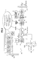
- a system of connection connects a analog subscriber telephone installation and digital essentially comprising a terminal analog telephone subscriber TA, such as an extension telephone subscriber and a subscriber terminal TN digital telephone, such as a micro computer PC staff at a telephone switch analog CM in a central office CT of public switched telephone network PSTN and at a node a broadband telecommunications network, such than an RO router of the NET internet network.
- a terminal analog telephone subscriber TA such as an extension telephone subscriber
- a subscriber terminal TN digital telephone such as a micro computer PC staff
- a telephone switch analog CM in a central office CT of public switched telephone network PSTN and at a node a broadband telecommunications network, such than an RO router of the NET internet network.
- the line LN has, according to the invention, one end on the subscriber installation side connected to a first equipment, called EA subscriber equipment, and a second end on the switch side telephone and router connected to a second equipment, called EC central office equipment.
- EA subscriber equipment is connected to the terminal analog telephone TA and terminal digital telephone TN respectively through an analog line with two wires LTA and a line of digital data with two pairs of LDN wires relatively short.
- the EC central office equipment is connected to a CM switch port across a line relatively short two-wire analog LAC and is suitable for conveying first analog signals to transmit to this analog terminal TA and second analog signals from the terminal analog TA.
- the RO router is connected by a line two-way LM two-way multiplex pairs of wires to multiplex equipment and EMD demultiplexing of which an access is connected by a short basic digital line LNB to an access digital EC central office equipment.
- the LN line constitutes a two-way digital line that carries a multiplex of digital channels of type 2B + D also well in the direction of transmission of a channel two-wire transmission from the equipment subscriber EA to central office equipment EC only in the direction of transmission from a reception channel to two VR wires from EC central equipment to EA subscriber equipment.
- the two B channels each have a throughput of 64 kbit / s and are operated in circuit mode or in frame.
- the first channel is dedicated to digital transmission of the first and second analog signals exchanged between a terminal analog TA and CM switch
- the second channel B2 is dedicated to the transmission of second and fourth data signals exchanged between the digital terminal TA and the router RO.
- Channel D has a speed of 16 kbit / s and supports signaling between the two EC devices and EA, and especially the first and second telephone signaling signals produced by the switch CM and by the analog terminal TA, to be digitally converted to be transmitted in the digital line LN.
- each direction of transmission in the digital line LN offers a total speed of 160 kbit / s, the 16 kbit / s remaining being occupied in particular by a channel of CMS maintenance and supervision at 4 kbit / s.
- each pair of bits 2B of each channel is converted into a quaternary symbol 1Q according to a 2B1Q coding whose coding table is as follows: 2B 1Q 00 - 3 01 - 1 11 +1 10 + 3
- the modulation speed in the digital line LN is thus equal to 80 kbauds, in correspondence with the speed of 160 kbit / s.
- the invention is not limited to the example of LN digital link described above. Indeed, as will be seen below, the exchanges of signals between EC and EA equipment are independent of support and technology transmission selected.
- the signals in the digital line to two LN wires are coded according to the code 4B3T, i.e. according to a four-bit coding in three symbols ternaries;
- the physical support of the LN line can include two optical fibers instead of a pair symmetrical of wires, or even at least partially a two-way radio link.
- the digital signage supported by the channel D following each of the directions of transmission of the digital line LN is independent of the setting telephone communications and additional telephone services provided to terminal TA by the switch CM.
- the signaling signals conform to the protocol D and can be messages for establishment of an incoming call from a caller away from TA terminal or outgoing call from the TA terminal, such as establishment messages and establishment acknowledgment; of informational messages with their accused messages reception relating to pulse start and end ringing call, digits of decimal numbering, tax pulses, current loop closures or openings in analog LAC and LTA lines, etc. ; and call disconnection and release messages.
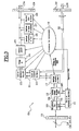
- the role of EC central office equipment essential, depending on the direction of the VE emission channel, to separate the "analog" stream in channel B1 and the digital flow in channel B2 to direct them respectively to the CM switch and the router RO, and depending on the direction of the VR reception channel, approximate the analog flow of the CM switch and the RO router digital stream in channels B1 and B2 to bring them together in a transmission medium common consisting of the digital subscriber line LN.
- the equipment of central EC is organized around a processor treatments 1.
- the first signal signals telephone transmitted by the CM switch through the analog line LAC are detected by detectors 2 to 5 and are analyzed by processor 1 which retransmits them in the form of first messages digital telephone signaling in the D channel of the VR reception channel in the equipment EC.
- second digital messages relating to the telephone signaling transmitted initially by the TA terminal are detected by the processor 1 in channel D of the transmission channel VE via circuit 11 in the EC equipment to be retransmitted as second signals analog telephone signaling in the analog LAC line to CM switch.
- the processor 1 also ensures permanent activation of the digital line LN for layers 1 and 2 of the ISO model in signaling channel D.
- EC central office equipment On the CM switch side, EC central office equipment includes a ring signal 2, a pulse detector tax 3, a reverse polarity detector 4, a reduced current detector 5 and a circuit bidirectional low frequency filtering 6 connected in parallel on the analog LAC line through a protection circuit 7.
- the analog line LAC is terminated by a line socket relay circuit 8 controlled by processor 1 in order to simulate in the analog line LAC of the second signals analog signaling in the form of loop closures in response for example to stalls or in the form of loop openings in response for example to hang-ups in the TA terminal.
- Ring signal detector 2 detects any type of ringing signal whatever or the type of the CM telephone switch. So, the ring detector 2 includes several filters bandpass having narrow centered bands respectively on the different frequencies of ringing of current telephone switches, by example at 25 Hz, 30 Hz, 50 Hz, 60 Hz and 75 Hz. ring detector 2 signals the start of a ringing pulse modulating a sinusoidal current at the frequency determined by the CM switch and any end of ring pulse, regardless of length of the pulse which can be between 0.7 s and 1.5 s and therefore whatever the length of intervals of silence between ringing pulses which can be between 0.7 s and 3.5 s.
- Tax pulse detector 3 detects any tax pulse transmitted by the CM switch in the LAC telephone line outside the band frequency at around 4 kHz for signals from speech. Tax pulse detector 3 is capable of detecting any tax pulse produced by current telephone switches. In this regard, the tax pulse detector 3 includes bandpass filters with narrow bands centered respectively on the frequencies of modulation of the different tax pulses, notably equal to 12 kHz and 16 kHz.
- Reverse polarity detector 4 detects any reverse polarity between the two wires of the analog line LAC. Indeed, for some switches, picking up or hanging up the caller or called party is signaled by a reversal polarity in the analog subscriber line. The polarity is said to be direct or normal when the line analog is not busy, and polarity is said inverted when the analog line is busy, between the dropout and hangup phases of a communication.
- the reduced current detector 5 compares permanently the magnitude of the supply current of the analog line LAG imposed by the battery supply in the central CT at a threshold of predetermined current. This threshold corresponds to a very low current applied by the CM switch when the LTA line is in a false call state, and as a result the LAC line is also in false condition call. This false call results from a dropout in the TA terminal extended beyond a long duration predetermined.
- Central office equipment signals then by a current signaling message reduces current state reduced to EA equipment to apply it in the LTA line.
- Each of detectors 2 to 5 samples each first analog signal signaling it monitors as quickly as possible, for example every 10 ms, and does not validate the changes of the signal to processor 1 only after confirmation by one or two additional samples for prevent the analog signaling reproduced by subscriber equipment does not comply with templates imposed.
- detectors 2 to 5 give a universal character to EC center equipment in relation to known telephone switches.
- the low frequency filtering circuit 6 bidirectionally filters the first and second analog signals in the audio band less than 4 kHz, typically between 300 Hz and 3400 kHz.
- the filtering circuit is connected to a coupling, equalization and conversion circuit 9.
- the latter circuit includes a two coupler wires / four wires so as to decouple from the line analog two-wire LAC channel Bl of the channel two-wire transmission line VE and channel B1 two-wire VR receiver, and equalizers for the VR and VE tracks, if necessary supplemented by a echo canceller.
- Circuit 9 also includes a analog to digital converter 8 kHz sampling to convert first speech signals but also signals determined telephone signaling, or any other analog signal transmitted in the band 4 kHz audio frequency via CM switch of the first digital signals conveyed in the channel B1 at 64 kbit / s of the VR reception channel, after transmitting a signal to EA subscriber equipment in the digital line LN.
- Signaling signals particular telephone signals are information about a remote caller, a dial tone call tone, dialing tone, ringback tone and a dial tone invitation to hang up.
- a converter digital-analog in circuit 9 converts third digital signals of channel B1 received from the VE transmission channel through the digital LN line in second analog speech signals, or especially in dialing signals to multifrequency, transmitted in the analog line LAC to the CM switch.
- a circuit bidirectional connection 10 controlled by the processor 1 connects to an insertion circuit and D 11 channel extraction circuit 9 assigned to Bl channel and the corresponding digital access of EMD multiplexing and demultiplexing equipment assigned to second and fourth signals digital in the second channel B2.
- EDM actually serves basic digital lines bidirectional at 64 kbit / s, 31 devices central of the invention intended for the second channels B2 in 31 EC central systems equipment telephone subscriber connection according to the invention whose first B1 channels are related to 31 analog LAC lines connected to the CM switch.
- the LM multiplex line supports 2048 kbit / s frames according to ITU standards G703 and G704. Each frame has 31 time slots occupied by basic channels B1 at 64 kbit / s and an interval of time occupied in particular by a lock word from frame.
- EDM equipment multiplexes 31 channels B1 in the LM line to transmit them multiplexed to time division at RO router, and demultiplex 31 LM line B1 channels to apply to access corresponding input circuits 10 included in the 31 EC exchange equipment.
- connection circuit 10 gathers byte by byte the first digital signals in the channel B1 at 64 kbit / s transmitted by the converter analog-digital of circuit 6 and the second digital signals in channel B2 at 64 kbit / s transmitted by a demultiplexer in the EMD equipment by multiplexing them time division into a signal 128 kbit / s intermediate multiplex depending on the direction of the VR reception channel.
- the circuit connection 10 separates the third and fourth digital signals in the two channels B1 and B2 of the VE emission channel by demultiplexing them towards the digital to analog converter in circuit 6 and to a multiplexer in the EMD equipment.
- circuit 11 Under the control of processor 1, circuit 11 inserts NMDS signaling messages into the 16 kbit / s D channel for the division division multiplexer time with the two channels B1 and B2 in the path of VR reception, and vice versa, extract messages from NMDS signaling of the D channel multiplexed with channels B1 and B2 in the transmission channel VE.
- EC central office equipment also includes, between the channel insertion and extraction circuit D 11 and a second protection circuit 12 connected to the digital line LN, an interface coding / decoding 13 and a remote supply circuit and coupling two wires / four wires 14 which are associated with a control and supervision circuit 15.
- the coding / decoding interface 13 according to the direction the reception channel VR multiplexes the channels B1, B2 and D with other channels, in particular the CMS maintenance and supervision at 4 kbit / s, provided by the control and supervision circuit 15 in one 80 kbaud multiplex signal coded according to the code 2B1Q.
- the interface 13 demultiplexes the two channel groups in the VE transmit channel for supply the multiplexed channels B1, B2 and D to the circuit 11 and the other 16 kbit / s channels on the command and supervision 15, after 1Q2B decoding in binary code.
- the remote supply circuit 14 provides classic way the remote power supply of the line digital LN, the EC and EA equipment being preferably autonomous, and couples the transmission channels EV and VR reception each with two wires with the two-way digital two-wire subscriber line LN.
- EA subscriber equipment The essential role of EA subscriber equipment is depending on the direction of the VE transmission channel, to bring essentially analog speech flow produced by the TA terminal through the LTA line and the flow digital data produced by the TN terminal in channels B1 and B2 to join them in a support common transmission consisting of the line digital LN, and according to the direction of the VR reception, to separate the "analog" stream and the digital flow in channels B1 and B2 of the line digital LN to direct them to the terminal analog TA and the digital subscriber terminal TN.
- the EA subscriber equipment includes, as shown in Figure 3, analogously to the equipment of EC center a processing processor 16.
- the processor 16 analyzes the first messages digital signaling transmitted by the CM switch via the LN line and the VR reception channel in EA equipment for retransmit as first signals from telephone signaling in the analog line LTA to TA terminal.
- processor 16 In the EV emission channel EA equipment, processor 16 generates second digital signaling messages mainly corresponding to stalls and hang-ups and possibly number pulses in decimal code established in the TA terminal.
- Processor 16 provides also the permanent activation of the line digital LN for layers 1 and 2 of the ISO model in signaling channel D.
- the EA subscriber equipment On the LN line side, the EA subscriber equipment has a circuit for inserting and extracting signaling channel D 17, a protection circuit 18, a coding / decoding and coupling interface two-wire / four-wire 19, a recovery circuit remote supply 20 connected to the digital line LN through the protection circuit 18, and a circuit 21 respectively analogous to circuits 11, 12, 13, 14 and 15 and arranged like these.
- a bidirectional connection circuit 22 is connected by a multiplexing / demultiplexing port of channels B to the insertion and extraction circuit of channel D 17, through a channel port B1 to a digital-to-analog and analog-to-digital conversion and equalization and coupling two wires / four wires 23 analogous to circuit 9, and by a channel port B2 to digital data line at 4 LDN wires through a protection circuit 30.
- connection circuit 22 separates byte by byte the first and second digital signals received in the two 64 kbit / s B1 and B2 channels of the VR reception through circuits 18, 20, 19 and 17 and demultiplex them to a port connected to a digital to analog converter in circuit 23 which converts the first digital signals into first analog signals to the TA terminal, and a port connected to the LDN digital line.
- the connection circuit 22 time division multiplex with channel B2 the second digital signals in channel B1 supplied by conversion of second signals analog in an analog to digital converter in circuit 23.
- the second signals analog are basically speech and the if necessary number digits in code multi-frequency transmitted by the TA terminal.
- the canal B2 supports fourth digital signals from data transmitted in the LDN line by the terminal TN, and is multiplexed with channel B1 into a signal 128 kbit / s intermediate multiplex to the channel of emission VE.
- Circuit 23 is connected to the end of the analog subscriber line LA1 through a circuit of 24 low frequency filtering and one circuit reverse polarity 25.
- the filter circuit like circuit 6, bi-directional filter in the audio frequency band below 4 kHz.
- the circuit 25 requires any polarity reversal between the two sons of the LTA line in response to a message signaling signaling a reverse polarity detected by detector 4. Circuits 24 and 25 correspond to circuits 6 and 4 in the equipment EC.
- the EA subscriber equipment also includes a tax pulse transmitter 26 and a transmitter ring and tone signal 27 so that reproduce tax pulses and pulses ringing clock on line LA1 in response to those detected by detectors 2 and 3 in the EC equipment, and a loop state detector 28 to signal a loop closure or a loop opening in the subscriber line TA in response to a dropout or a hang up in the TA terminal, or opening torques of loop and loop closure in line LA1 corresponding to a decimal number, in the form of respective signaling messages in channel D of the transmission channel VE.
- Ports of the reverse polarity circuit 25, of the transmitters 26 and 27 and detector 28 are connected to a end of the analog LTA line through a protection circuit 29.
- multiplexing static analog signals in the line LTA analog telephone and digital signals in the digital data line LDN is replaced by dynamic multiplexing.
- the bandwidth of the digital link LN is thus allocated dynamically based on traffic between the router RO of the digital broadband NET network and the TN digital terminal.
- B1 channel allocations and B2 may be different in the channels transmission and reception channels. For example, when the subscriber wishes to record in his microcomputer TN files transmitted across the RO router, only channel B2 in the channel transmission station is busy to request this transfer file, while the two channels B1 and B2 in the VR receive channel are occupied by data transferred files.
- the assignment of the first channel B1 to a data communication between the TN digital terminal and RO router is performed via a message establishing the channel B1 emitted by one of the EAa and ECa devices having received a request to increase the speed of the traffic from terminal TA or from router RO, and from a acknowledgment of receipt in the form of a message from connection from other equipment to establish at least the desired one-way link B1 + B2 in the digital link ECa-LN-EAa.
- connection circuit 10a is connected by two lines bidirectional digital each to two pairs of wires to multiplexing and demultiplexing equipment EMD.
- the processor allocates it a B2 channel or two channels B2 and B1 for one and / or the other of direction of transmission.
- Digital access between EMD equipment and connection circuit 10 is thus at 64 kbit / s or 128 kbit / s.
- multiplex signals intermediaries B1 + B2 are applied to the processor the through the connection circuit 10a.
- the processing processor 16a is interconnected between digital access of connection circuit 22a serving the TN digital terminal and the interface 30a connected to the digital data line LDN.
- the processor 16a like the processor la in ECa central office equipment, ensures fragmentation data between channels B1 and B2 according to the direction of the EV transmission channel and the grouping of data of channels B1 and B2 according to the direction of the VR reception channel depending on signaling transmitted by the TN terminal or by channel D of the VR reception channel.
- the arrangement of others circuits 17 to 29 shown in Figure 3 remains in the second embodiment shown in Figure 5.
- EAa subscriber equipment could negotiate allocated channels with sound counterpart, ECa central office equipment, the aforementioned protocols MLPPP, BOD, BACP and BAP are of preferably located in the TN digital terminal to lower the cost of subscriber equipment EAa.
- subscriber equipment Ea has analog telephone access additional connected by a second line analog telephone LTA2.
- This LTA2 line is typically connected to an included phone card in the TN microcomputer (PC) so that the voice of the subscriber in front of his microcomputer forming third analog signals be transmitted according to the Internet Protocol (IP) network protocol NET broadband network in channel D of the channel of transmission VE, and vice versa of the transmitted voice according to the IP network protocol in channel D of the VR reception channel is received after conversion, in as fourth analog signals, in the microcomputer, based on protocols ITU Q921 and I430.
- IP Internet Protocol
- EAa subscriber equipment includes a circuit for conversion of third analog signals into IP data messages and IP data messages into fourth analog and equalization signals and 2-wire / 4-wire coupling 23a, a filter circuit at low frequency 24a, a reversing circuit of polarity 25a, a ring signal and tone 27a, a loop state detector 28a and a protection circuit 29a which are respectively arranged in the same way as circuits 23, 24, 25, 27, 28 and 29 at the end of the first line analog telephone LTA.
- a detector digit number in multifrequency code DTMF (Dual-Tone Multifrequency) 31 detects dual frequency signals transmitted over the line LTA2 telephone and corresponding to digits of a called number.
- Circuit 23a also integrates the IP network protocol of so as to convert the third signals analog voice received from the LTA2 line in digital data messages according to datagrams IP with a speed lower than 16 kbit / s.
- processor 16a is also installed the IP network protocol with transport protocol TCP (Transmission Control Protocol) so that signaling signals detected in the LTA2 line by detectors 28a and 31 be converted into digital signaling messages according to IP network protocol and be transmitted, like the IP protocol data messages delivered via circuit 23a, in signaling channel D at 16 kbit / s also supporting the second related telephone signaling messages with detector 28.
- TCP Transmission Control Protocol
- the channel D signaling supporting these three types of interleaved messages is multiplexed with the channel B1 data supporting the third signals numbers relating to the TA terminal and the B2 data supporting the fourth signals digital signals transmitted by the TN terminal.
- the circuit 23a is also connected to the processor processing 16a so that it manages dynamically the different data links relating to TN terminal data via the line LDN, the analog voice of the TA terminal via the line LTA and the voice of the TN terminal via the LTA2 line intertwined with telephone signals.
- the links of message data according to IP protocol and telephone signaling messages relating to the TA terminal are differentiated particularly in the SAPI address fields and TEI of data frames.
- the telephone signaling from the line LTA analog telephone has priority by voice and telephone signaling from the LTA2 analog telephone line.
- the circuit 17 extracts the signaling channel D received from the digital subscriber line LN so that the processor 16a separates messages from telephone signaling intended for circuits 25, 26 and 27 relating to the analog terminal TA and the signaling messages according to the IP network intended for circuits 25a and 27a relative to the TN digital terminal, and data messages according to the IP network protocol intended for the circuit 23a.
- Circuit 23a converts data messages received according to the IP protocol in fourth signals analog voice transmitted to the digital terminal TN.
- Telephone signaling messages received according to the IP protocol are converted into commands circuits 25a and 27a so that these transmit telephony signals to the card telephone terminal TN.
- the data and telephone signaling messages according to the IP network protocol are extracted from D channel received from digital subscriber line LN so the processor processes the message routing IP, like channel B2, through the circuit connection 10a.
- Both digital accesses bidirectional at 64 kbit / s connected to the EMD multiplexing and demultiplexing are respectively allocated, according to this third realization, to data channel B2 and to messages data signaling and signaling using the IP protocol.
- Channel B1 for the telephone data passes through circuit 9, as in the first embodiment.
- the processor inserts these messages in signaling channel D which is multiplexed with channels B1 and B2 of the VR reception channel in circuit 110.
Landscapes
- Engineering & Computer Science (AREA)
- Computer Networks & Wireless Communication (AREA)
- Signal Processing (AREA)
- Telephonic Communication Services (AREA)
Abstract
Description
- interdiction d'utiliser le terminal téléphonique analogique pendant que le terminal numérique est en communication avec le réseau Internet ;
- facturation des communications téléphoniques à la durée pénalisant l'abonné pendant de longues connexions avec le réseau Internet, en opposition avec la tarification au forfait des communications sur le réseau Internet ;
- occupation du commutateur téléphonique local pendant la communication avec le réseau Internet ce qui offre un risque d'encombrement et d'insatisfaction des autres abonnés locaux désirant établir des communications téléphoniques.
- un premier équipement comprenant un moyen pour convertir des premiers signaux analogiques transmis par le commutateur en des premiers signaux numériques, un moyen pour regrouper les premiers signaux numériques et des deuxièmes signaux numériques transmis par le noeud et destinés au terminal numérique en deux canaux numériques multiplexés transmis dans une ligne téléphonique d'abonné vers les terminaux, un moyen pour séparer deux canaux numériques multiplexés de la ligne téléphonique en des troisièmes signaux numériques relatifs à des signaux du terminal analogique et des quatrièmes signaux numériques qui sont relatifs à des données du terminal numérique et qui sont transmis vers ledit noeud, et un moyen pour convertir les troisièmes signaux numériques en des deuxièmes signaux analogiques transmis au commutateur ; et
- un deuxième équipement comprenant un moyen pour séparer les canaux numériques multiplexés transmis via la ligne téléphonique en les premiers signaux numériques et les deuxièmes signaux numériques transmis au terminal numérique, un moyen pour convertir les premiers signaux numériques séparés en les premiers signaux analogiques qui sont transmis au terminal analogique, un moyen pour convertir des deuxièmes signaux analogiques provenant du terminal analogique en des troisièmes signaux numériques, et un moyen pour regrouper les troisièmes signaux numériques précités et des quatrièmes signaux numériques transmis par le terminal numérique en deux canaux numériques multiplexés transmis dans la ligne téléphonique d'abonné.
- la figure 1 montre un système de raccordement entre des terminaux téléphoniques analogiques et numériques et un commutateur téléphonique analogique et un routeur de réseau numérique à haut débit selon l'invention ;
- la figure 2 est un bloc-diagramme détaillé du deuxième équipement, dit équipement de central, du côté du commutateur et du routeur selon une première réalisation de l'invention ;
- la figure 3 est un bloc-diagramme détaillé du premier équipement, dit équipement d'abonné, du côté des terminaux selon une première réalisation de l'invention ;
- la figure 4 est un bloc-diagramme détaillé de l'équipement de central selon une deuxième réalisation de l'invention ; et
- la figure 5 est bloc-diagramme détaillé de l'équipement d'abonné selon une deuxième réalisation de l'invention.
| 2B | 1Q |
| 00 | - 3 |
| 01 | - 1 |
| 11 | + 1 |
| 10 | + 3 |
- pour une communication analogique à travers les lignes LAC et LTA relative au premier canal B1, les messages contiennent les identificateurs SAPI = 0 et TEI = 126 ;
- pour une communication numérique à travers la ligne LDN et l'équipement EMD relative au deuxième canal B2, les messages contiennent les identificateurs SAPI = 0 et TEI = 125.
Claims (8)
- Système de raccordement entre une installation téléphonique d'abonné incluant un terminal analogique (TA) et un terminal numérique (TN) d'une part, et un commutateur téléphonique analogique (CM) et un noeud d'accès (RO) d'un réseau numérique à haut débit (NET), d'autre part, caractérisé en ce qu'il comprend :un premier équipement (EC) comprenant un moyen (9) pour convertir des premiers signaux analogiques (LAC) transmis par le commutateur (CM) en des premiers signaux numériques (B1), un moyen (1, 10) pour regrouper les premiers signaux numériques et des deuxièmes signaux numériques (B2) transmis par le noeud (RO) et destinés au terminal numérique (TN) en deux canaux numériques multiplexés (B1, B2) transmis dans une ligne téléphonique d'abonné (LN) vers les terminaux, un moyen (1, 10) pour séparer deux canaux numériques multiplexés (B1, B2) de la ligne téléphonique (LN) en des troisièmes signaux numériques (B1) relatifs à des signaux du terminal analogique (TA) et des quatrièmes signaux numériques (B2) qui sont relatifs à des données du terminal numérique (TN) et qui sont transmis vers ledit noeud (RO), et un moyen (9) pour convertir les troisièmes signaux numériques en des deuxièmes signaux analogiques (LAC) transmis au commutateur ; etun deuxième équipement (EA) comprenant un moyen (16, 22) pour séparer les canaux numériques multiplexés (B1, B2) transmis via la ligne téléphonique (LN) en les premiers signaux numériques (LTA) et les deuxièmes signaux numériques (LDN) transmis au terminal numérique (TN), un moyen (23) pour convertir les premiers signaux numériques séparés (B1) en les premiers signaux analogiques (LTA) qui sont transmis au terminal analogique (TA), un moyen (23) pour convertir des deuxièmes signaux analogiques (LTA) provenant du terminal analogique (TA) en des troisièmes signaux numériques (B1), et un moyen (1, 22) pour regrouper les troisièmes signaux numériques précités et des quatrièmes signaux numériques transmis par le terminal numérique (TN) en deux canaux numériques multiplexés (B1, B2) transmis dans la ligne téléphonique d'abonné (LN).
- Système conforme à la revendication 1, comprenant un troisième équipement numérique (EMD) commun à plusieurs premiers équipements (EC) pour démultiplexer un signal multiplex (LM) transmis par le noeud (RO) en plusieurs deuxièmes signaux numériques (B2) respectivement appliqués aux moyens pour regrouper (1, 10) inclus dans lesdits plusieurs premiers équipements, et pour multiplexer plusieurs quatrièmes signaux numériques (B2) respectivement fournis par les moyens pour séparer (1, 10) inclus dans lesdits premiers équipements en un signal multiplex (LM) transmis au noeud (RO).
- Système conforme à la revendication 1 ou 2, dans lequel le premier équipement (EC) comprend en outre des moyens (2-5) pour détecter des premiers signaux de signalisation téléphonique analogiques transmis par le commutateur (CM) et un moyen (1, 11) pour insérer des premiers messages numériques de signalisation téléphonique dans un canal de signalisation (D) respectivement en réponse aux premiers signaux de signalisation détectés afin de multiplexer les deux canaux numériques (B1, B2) avec le canal de signalisation (D) pour les transmettre dans la ligne téléphonique d'abonné (LN) vers le deuxième équipement, un moyen (1, 11) pour extraire et analyser des deuxièmes messages de signalisation du canal de signalisation reçus de la ligne téléphonique et des moyens (1, 8) pour transmettre les deuxièmes signaux analogiques de signalisation au commutateur (CM) respectivement en réponse aux deuxièmes messages de signalisation analysés.
- Système conforme à l'une quelconque des revendications 1 à 3, dans lequel le deuxième équipement (EA) comprend en outre un moyen (17, 16) pour extraire et analyser les premiers messages de signalisation du canal de signalisation reçus de la ligne téléphonique, des moyens (16, 25-27) pour transmettre les premiers signaux analogiques de signalisation au terminal analogique (TA) respectivement en réponse aux premiers messages de signalisation analysés, des moyens (16, 28) pour détecter des deuxièmes signaux de signalisation téléphonique analogiques transmis par le terminal analogique (TA), et un moyen (16, 17) pour insérer des deuxièmes messages numériques de signalisation téléphonique dans le canal de signalisation (D) respectivement en réponse aux deuxièmes signaux de signalisation détectés afin de multiplexer les deux canaux numériques (B1, B2) avec le canal de signalisation (D) pour les transmettre dans la ligne téléphonique d'abonné (LN) vers le premier équipement (EC).
- Système conforme à l'une quelconque des revendications 1 à 4, dans lequel le premier équipement (ECa) et l'un des deuxième équipement (EAa) et terminal numérique (TN) comprennent des moyens (1a, 10a, 11a ; 22a, 16a ou TN) pour allouer dynamiquement l'un des ou les deux canaux numériques (B1, B2) suivant l'un et/ou l'autre des sens de transmission (VE, VR) de la ligne téléphonique d'abonné (LN) à une communication de données entre le noeud (RO) et le terminal numérique (TN) en fonction des trafics de données demandés par l'un et/ou l'autre des noeud et terminal numérique.
- Système conforme à l'une quelconque des revendications 1 à 5, dans lequel le deuxième équipement (EAa) comprend en outre un moyen (23a) pour convertir des troisièmes signaux analogiques notamment de voix (LTA2) provenant du terminal numérique (TN) en des messages numériques de données selon un protocole de réseau du réseau à haut débit (NET), des moyens (16a, 28a, 31) pour détecter des troisièmes signaux de signalisation téléphonique transmis par le terminal numérique (TN) afin de les convertir en des messages numériques de signalisation selon le protocole de réseau, un moyen (16a, 17, 22a) pour insérer les messages de données et de signalisation selon le protocole de réseau dans un canal de signalisation (D) afin de les multiplexer avec les deux canaux numériques (B1, B2) dans la ligne téléphonique d'abonné vers le premier équipement (ECa), un moyen (16a, 17, 22a) pour extraire et analyser des messages numériques de données et de signalisation selon le protocole de réseau du canal de signalisation (D) reçus de la ligne téléphonique, un moyen (23a) pour convertir les messages numériques de données selon le protocole de réseau extraits en des quatrièmes signaux analogiques notamment de voix (LTA2) transmis au terminal numérique (TN), et des moyens (16a, 25a, 27a) pour transmettre des quatrièmes signaux de signalisation téléphonique au terminal numérique en réponse aux messages de signalisation extraits selon le protocole de réseau.
- Système conforme à l'une quelconque des revendications 1 à 6, dans lequel le premier équipement (ECa) comprend en outre un moyen (11a, 1a, 10a) pour extraire et analyser des messages numériques de données et de signalisation selon le protocole de réseau du canal de signalisation (D) reçus de la ligne téléphonique afin de les transmettre, en tant que quatrièmes signaux numériques, vers ledit noeud (RO), et un moyen (10a, 1a, 11a) pour insérer des messages de données et de signalisation selon le protocole de réseau transmis par le noeud (RO) dans le canal de signalisation (D) afin de le multiplexer avec les deux canaux numériques (B1, B2) pour les transmettre dans la ligne téléphonique d'abonné (LN) vers le deuxième équipement (EAa).
- Système conforme à l'une quelconque des revendications 1 à 7, dans lequel la ligne téléphonique d'abonné est une ligne à deux fils (LN) qui convoie pour chaque sens de transmission au moins les deux canaux numériques multiplexés (B1, B2) avec un canal de signalisation (D) supportant des messages de signalisation.
Applications Claiming Priority (2)
| Application Number | Priority Date | Filing Date | Title |
|---|---|---|---|
| FR9905152A FR2792796B1 (fr) | 1999-04-22 | 1999-04-22 | Systeme raccordant une installation telephonique d'abonne au reseau telephonique commute et a un reseau numerique a haut debit |
| FR9905152 | 1999-04-22 |
Publications (2)
| Publication Number | Publication Date |
|---|---|
| EP1047257A1 true EP1047257A1 (fr) | 2000-10-25 |
| EP1047257B1 EP1047257B1 (fr) | 2008-05-21 |
Family
ID=9544775
Family Applications (1)
| Application Number | Title | Priority Date | Filing Date |
|---|---|---|---|
| EP00401083A Expired - Lifetime EP1047257B1 (fr) | 1999-04-22 | 2000-04-18 | Système raccordant une installation téléphonique d'abonné au réseau téléphonique commuté et à un réseau numérique à haut débit |
Country Status (4)
| Country | Link |
|---|---|
| EP (1) | EP1047257B1 (fr) |
| DE (1) | DE60038920D1 (fr) |
| ES (1) | ES2307488T3 (fr) |
| FR (1) | FR2792796B1 (fr) |
Citations (1)
| Publication number | Priority date | Publication date | Assignee | Title |
|---|---|---|---|---|
| WO1997050230A2 (fr) * | 1996-06-24 | 1997-12-31 | Ericsson Inc. | Commutateur de telecommunication comprenant un serveur d'acces a internet integre |
-
1999
- 1999-04-22 FR FR9905152A patent/FR2792796B1/fr not_active Expired - Fee Related
-
2000
- 2000-04-18 ES ES00401083T patent/ES2307488T3/es not_active Expired - Lifetime
- 2000-04-18 EP EP00401083A patent/EP1047257B1/fr not_active Expired - Lifetime
- 2000-04-18 DE DE60038920T patent/DE60038920D1/de not_active Expired - Lifetime
Patent Citations (1)
| Publication number | Priority date | Publication date | Assignee | Title |
|---|---|---|---|---|
| WO1997050230A2 (fr) * | 1996-06-24 | 1997-12-31 | Ericsson Inc. | Commutateur de telecommunication comprenant un serveur d'acces a internet integre |
Non-Patent Citations (2)
| Title |
|---|
| ARKKO J ET AL: "DIAL-UP SERVICE VIA THE INTEGRATED ACCESS SYSTEM", ERICSSON REVIEW,SE,ERICSSON. STOCKHOLM, no. SPEC. INT. ISS, 1 January 1998 (1998-01-01), pages 14 - 19, XP000751710, ISSN: 0014-0171 * |
| SIMEONOV P L ET AL: "INGATE: A DISTRIBUTED INTELLIGENT NETWORK APPROACH TO BRIDGE SWITCHING AND PACKET NETWORKS", PROCEEDINGS OF THE INTERNATIONAL CONFERENCE ON COMPUTER COMMUNICATIONS AND NETWORKS, 1 January 1997 (1997-01-01), XP002073675 * |
Also Published As
| Publication number | Publication date |
|---|---|
| EP1047257B1 (fr) | 2008-05-21 |
| DE60038920D1 (de) | 2008-07-03 |
| FR2792796A1 (fr) | 2000-10-27 |
| FR2792796B1 (fr) | 2001-06-22 |
| ES2307488T3 (es) | 2008-12-01 |
Similar Documents
| Publication | Publication Date | Title |
|---|---|---|
| CA1150429A (fr) | Installation de commutation numerique a division du temps pour des lignes vehiculant la parole et des paquets de donnees | |
| EP0851653B1 (fr) | Service téléphonique local sur un réseau cablé utilisant paquets vocaux | |
| US6128293A (en) | Multiservice access management system | |
| US5991292A (en) | Network access in multi-service environment | |
| EP0868051A2 (fr) | Procédé et dispositif pour l'acheminement d'appèls à partir d'un site central | |
| EP0133703B1 (fr) | Centre satellite numérique de raccordement d'abonnés | |
| EP0608170A1 (fr) | Procédé et terminal de visiophonie permettant l'accueil, et éventuellement l'appel, par un poste téléphonique | |
| EP0254920B1 (fr) | Système de rattachement d'abonnés téléphoniques organisé autour d'un autocommutateur temporel numérique | |
| EP1047257B1 (fr) | Système raccordant une installation téléphonique d'abonné au réseau téléphonique commuté et à un réseau numérique à haut débit | |
| FR2744315A1 (fr) | Terminal voix-donnees pour reseau telephonique radio | |
| FR2749471A1 (fr) | Systeme de telephone numerique sans fil | |
| FR2474261A1 (fr) | Systeme de transmission numerique pour telecopieur | |
| WO2002058352A1 (fr) | Utilisation transparente, simultanee, d'une ligne telephonique pour les communications de voix et donnees | |
| EP0466590B1 (fr) | Système de communication numérique pour installation téléphonique à intégration de services | |
| EP0530098B1 (fr) | Agencement et procédé de communication entre unités d'une installation de communication | |
| EP1047254A1 (fr) | Système de raccordement entre un terminal analogique et un commutateur téléphonique analogique | |
| EP1014670A2 (fr) | Système de télécommunication et procédé avec une ligne d'abonné numérique (DSL) multicanaux | |
| EP1152634B1 (fr) | Equipement d'interconnexion entre une installation d'usager RNIS et un réseau IP/ATM | |
| EP1087580A2 (fr) | Système et circuit téléphonique | |
| US7366198B2 (en) | Method and system for packet and circuit telephony in a distributed telecommunications switching system | |
| EP1158755A2 (fr) | Procédé pour un serveur de connexion internet qui permet d'établir des artères de signalisation pour un réseau privé de télécommunication | |
| EP1267533A1 (fr) | Equipement de raccordement simultané d'au moins un accès en mode ATM et un accès de téléphonie en mode circuit à un lien de transmission haut débit | |
| FR2776876A1 (fr) | Procede de transmission telex, adaptateur de terminal telex, terminal et passerelle de reseau pour la mise en oeuvre du procede | |
| WO1995029569A1 (fr) | Installation telephonique a ligne de transmission numerique a debit reduit | |
| FR2870417A1 (fr) | Terminal de telecommunication pour reseau a integration de services rnis |
Legal Events
| Date | Code | Title | Description |
|---|---|---|---|
| PUAI | Public reference made under article 153(3) epc to a published international application that has entered the european phase |
Free format text: ORIGINAL CODE: 0009012 |
|
| AK | Designated contracting states |
Kind code of ref document: A1 Designated state(s): DE ES GB IT |
|
| AX | Request for extension of the european patent |
Free format text: AL;LT;LV;MK;RO;SI |
|
| 17P | Request for examination filed |
Effective date: 20010117 |
|
| AKX | Designation fees paid |
Free format text: DE ES GB IT |
|
| RAP1 | Party data changed (applicant data changed or rights of an application transferred) |
Owner name: SAFRAN |
|
| RAP1 | Party data changed (applicant data changed or rights of an application transferred) |
Owner name: SAGEM COMMUNICATION |
|
| GRAP | Despatch of communication of intention to grant a patent |
Free format text: ORIGINAL CODE: EPIDOSNIGR1 |
|
| RTI1 | Title (correction) |
Free format text: SYSTEM FOR CONNECTING A SUBSCRIBER TELEPHONE INSTALLATION WITH THE PSTN AND WITH A HIGH-THROUGHPUT DIGITAL NETWORK |
|
| GRAS | Grant fee paid |
Free format text: ORIGINAL CODE: EPIDOSNIGR3 |
|
| GRAA | (expected) grant |
Free format text: ORIGINAL CODE: 0009210 |
|
| AK | Designated contracting states |
Kind code of ref document: B1 Designated state(s): DE ES GB IT |
|
| REG | Reference to a national code |
Ref country code: GB Ref legal event code: FG4D Free format text: NOT ENGLISH |
|
| REF | Corresponds to: |
Ref document number: 60038920 Country of ref document: DE Date of ref document: 20080703 Kind code of ref document: P |
|
| RAP2 | Party data changed (patent owner data changed or rights of a patent transferred) |
Owner name: SAGEM COMMUNICATIONS |
|
| REG | Reference to a national code |
Ref country code: ES Ref legal event code: FG2A Ref document number: 2307488 Country of ref document: ES Kind code of ref document: T3 |
|
| PLBE | No opposition filed within time limit |
Free format text: ORIGINAL CODE: 0009261 |
|
| STAA | Information on the status of an ep patent application or granted ep patent |
Free format text: STATUS: NO OPPOSITION FILED WITHIN TIME LIMIT |
|
| 26N | No opposition filed |
Effective date: 20090224 |
|
| REG | Reference to a national code |
Ref country code: DE Ref legal event code: R082 Ref document number: 60038920 Country of ref document: DE Representative=s name: JOCHEN MUELLER, DE |
|
| REG | Reference to a national code |
Ref country code: GB Ref legal event code: 732E Free format text: REGISTERED BETWEEN 20130509 AND 20130515 |
|
| REG | Reference to a national code |
Ref country code: ES Ref legal event code: PC2A Owner name: SAGEMCOM ENERGY & TELECOM SAS Effective date: 20131009 |
|
| REG | Reference to a national code |
Ref country code: DE Ref legal event code: R082 Ref document number: 60038920 Country of ref document: DE Representative=s name: MAIWALD PATENTANWALTSGESELLSCHAFT MBH, DE Effective date: 20131212 Ref country code: DE Ref legal event code: R082 Ref document number: 60038920 Country of ref document: DE Representative=s name: MAIWALD PATENTANWALTSGESELLSCHAFT MBH, DE Effective date: 20120131 Ref country code: DE Ref legal event code: R081 Ref document number: 60038920 Country of ref document: DE Owner name: SAGEMCOM ENERGY & TELECOM SAS, FR Free format text: FORMER OWNER: SAGEM COMMUNICATIONS, PARIS, FR Effective date: 20131212 |
|
| PGFP | Annual fee paid to national office [announced via postgrant information from national office to epo] |
Ref country code: GB Payment date: 20150324 Year of fee payment: 16 |
|
| PGFP | Annual fee paid to national office [announced via postgrant information from national office to epo] |
Ref country code: ES Payment date: 20150408 Year of fee payment: 16 Ref country code: DE Payment date: 20150319 Year of fee payment: 16 |
|
| PGFP | Annual fee paid to national office [announced via postgrant information from national office to epo] |
Ref country code: IT Payment date: 20150330 Year of fee payment: 16 |
|
| REG | Reference to a national code |
Ref country code: DE Ref legal event code: R119 Ref document number: 60038920 Country of ref document: DE |
|
| GBPC | Gb: european patent ceased through non-payment of renewal fee |
Effective date: 20160418 |
|
| PG25 | Lapsed in a contracting state [announced via postgrant information from national office to epo] |
Ref country code: GB Free format text: LAPSE BECAUSE OF NON-PAYMENT OF DUE FEES Effective date: 20160418 Ref country code: DE Free format text: LAPSE BECAUSE OF NON-PAYMENT OF DUE FEES Effective date: 20161101 |
|
| PG25 | Lapsed in a contracting state [announced via postgrant information from national office to epo] |
Ref country code: IT Free format text: LAPSE BECAUSE OF NON-PAYMENT OF DUE FEES Effective date: 20160418 |
|
| PG25 | Lapsed in a contracting state [announced via postgrant information from national office to epo] |
Ref country code: ES Free format text: LAPSE BECAUSE OF NON-PAYMENT OF DUE FEES Effective date: 20160419 |
|
| REG | Reference to a national code |
Ref country code: ES Ref legal event code: FD2A Effective date: 20181130 |