EP1047138A1 - Battery power supply - Google Patents
Battery power supply Download PDFInfo
- Publication number
- EP1047138A1 EP1047138A1 EP20000108645 EP00108645A EP1047138A1 EP 1047138 A1 EP1047138 A1 EP 1047138A1 EP 20000108645 EP20000108645 EP 20000108645 EP 00108645 A EP00108645 A EP 00108645A EP 1047138 A1 EP1047138 A1 EP 1047138A1
- Authority
- EP
- European Patent Office
- Prior art keywords
- positive
- battery
- negative terminals
- battery modules
- power supply
- Prior art date
- Legal status (The legal status is an assumption and is not a legal conclusion. Google has not performed a legal analysis and makes no representation as to the accuracy of the status listed.)
- Granted
Links
- 238000003780 insertion Methods 0.000 claims description 16
- 230000037431 insertion Effects 0.000 claims description 16
- 238000012986 modification Methods 0.000 description 7
- 230000004048 modification Effects 0.000 description 7
- 230000013011 mating Effects 0.000 description 3
- 238000005192 partition Methods 0.000 description 3
- 239000011347 resin Substances 0.000 description 2
- 229920005989 resin Polymers 0.000 description 2
- 238000012790 confirmation Methods 0.000 description 1
- 229910052739 hydrogen Inorganic materials 0.000 description 1
- 239000001257 hydrogen Substances 0.000 description 1
- 230000002401 inhibitory effect Effects 0.000 description 1
- 238000000034 method Methods 0.000 description 1
- 238000000465 moulding Methods 0.000 description 1
- 239000011295 pitch Substances 0.000 description 1
- 229920000915 polyvinyl chloride Polymers 0.000 description 1
- 239000004800 polyvinyl chloride Substances 0.000 description 1
- 230000000007 visual effect Effects 0.000 description 1
Images




Classifications
-
- H—ELECTRICITY
- H01—ELECTRIC ELEMENTS
- H01M—PROCESSES OR MEANS, e.g. BATTERIES, FOR THE DIRECT CONVERSION OF CHEMICAL ENERGY INTO ELECTRICAL ENERGY
- H01M50/00—Constructional details or processes of manufacture of the non-active parts of electrochemical cells other than fuel cells, e.g. hybrid cells
- H01M50/20—Mountings; Secondary casings or frames; Racks, modules or packs; Suspension devices; Shock absorbers; Transport or carrying devices; Holders
- H01M50/204—Racks, modules or packs for multiple batteries or multiple cells
- H01M50/207—Racks, modules or packs for multiple batteries or multiple cells characterised by their shape
- H01M50/213—Racks, modules or packs for multiple batteries or multiple cells characterised by their shape adapted for cells having curved cross-section, e.g. round or elliptic
-
- H—ELECTRICITY
- H01—ELECTRIC ELEMENTS
- H01M—PROCESSES OR MEANS, e.g. BATTERIES, FOR THE DIRECT CONVERSION OF CHEMICAL ENERGY INTO ELECTRICAL ENERGY
- H01M50/00—Constructional details or processes of manufacture of the non-active parts of electrochemical cells other than fuel cells, e.g. hybrid cells
- H01M50/20—Mountings; Secondary casings or frames; Racks, modules or packs; Suspension devices; Shock absorbers; Transport or carrying devices; Holders
- H01M50/296—Mountings; Secondary casings or frames; Racks, modules or packs; Suspension devices; Shock absorbers; Transport or carrying devices; Holders characterised by terminals of battery packs
-
- H—ELECTRICITY
- H01—ELECTRIC ELEMENTS
- H01M—PROCESSES OR MEANS, e.g. BATTERIES, FOR THE DIRECT CONVERSION OF CHEMICAL ENERGY INTO ELECTRICAL ENERGY
- H01M50/00—Constructional details or processes of manufacture of the non-active parts of electrochemical cells other than fuel cells, e.g. hybrid cells
- H01M50/20—Mountings; Secondary casings or frames; Racks, modules or packs; Suspension devices; Shock absorbers; Transport or carrying devices; Holders
- H01M50/218—Mountings; Secondary casings or frames; Racks, modules or packs; Suspension devices; Shock absorbers; Transport or carrying devices; Holders characterised by the material
- H01M50/22—Mountings; Secondary casings or frames; Racks, modules or packs; Suspension devices; Shock absorbers; Transport or carrying devices; Holders characterised by the material of the casings or racks
- H01M50/227—Organic material
-
- H—ELECTRICITY
- H01—ELECTRIC ELEMENTS
- H01M—PROCESSES OR MEANS, e.g. BATTERIES, FOR THE DIRECT CONVERSION OF CHEMICAL ENERGY INTO ELECTRICAL ENERGY
- H01M50/00—Constructional details or processes of manufacture of the non-active parts of electrochemical cells other than fuel cells, e.g. hybrid cells
- H01M50/20—Mountings; Secondary casings or frames; Racks, modules or packs; Suspension devices; Shock absorbers; Transport or carrying devices; Holders
- H01M50/249—Mountings; Secondary casings or frames; Racks, modules or packs; Suspension devices; Shock absorbers; Transport or carrying devices; Holders specially adapted for aircraft or vehicles, e.g. cars or trains
-
- H—ELECTRICITY
- H01—ELECTRIC ELEMENTS
- H01M—PROCESSES OR MEANS, e.g. BATTERIES, FOR THE DIRECT CONVERSION OF CHEMICAL ENERGY INTO ELECTRICAL ENERGY
- H01M50/00—Constructional details or processes of manufacture of the non-active parts of electrochemical cells other than fuel cells, e.g. hybrid cells
- H01M50/50—Current conducting connections for cells or batteries
- H01M50/502—Interconnectors for connecting terminals of adjacent batteries; Interconnectors for connecting cells outside a battery casing
- H01M50/509—Interconnectors for connecting terminals of adjacent batteries; Interconnectors for connecting cells outside a battery casing characterised by the type of connection, e.g. mixed connections
- H01M50/51—Connection only in series
-
- H—ELECTRICITY
- H01—ELECTRIC ELEMENTS
- H01M—PROCESSES OR MEANS, e.g. BATTERIES, FOR THE DIRECT CONVERSION OF CHEMICAL ENERGY INTO ELECTRICAL ENERGY
- H01M50/00—Constructional details or processes of manufacture of the non-active parts of electrochemical cells other than fuel cells, e.g. hybrid cells
- H01M50/50—Current conducting connections for cells or batteries
- H01M50/543—Terminals
- H01M50/547—Terminals characterised by the disposition of the terminals on the cells
- H01M50/548—Terminals characterised by the disposition of the terminals on the cells on opposite sides of the cell
-
- Y—GENERAL TAGGING OF NEW TECHNOLOGICAL DEVELOPMENTS; GENERAL TAGGING OF CROSS-SECTIONAL TECHNOLOGIES SPANNING OVER SEVERAL SECTIONS OF THE IPC; TECHNICAL SUBJECTS COVERED BY FORMER USPC CROSS-REFERENCE ART COLLECTIONS [XRACs] AND DIGESTS
- Y02—TECHNOLOGIES OR APPLICATIONS FOR MITIGATION OR ADAPTATION AGAINST CLIMATE CHANGE
- Y02E—REDUCTION OF GREENHOUSE GAS [GHG] EMISSIONS, RELATED TO ENERGY GENERATION, TRANSMISSION OR DISTRIBUTION
- Y02E60/00—Enabling technologies; Technologies with a potential or indirect contribution to GHG emissions mitigation
- Y02E60/10—Energy storage using batteries
Definitions
- the present invention relates to a battery power supply in which its battery modules can easily be attached to the battery case.
- This battery power supply which is used as a motor driving power supply for an electric vehicle or a hybrid vehicle.
- This battery power supply comprises multiple battery modules each of which has a line of cells electrically and mechanically connected together in series and which are housed in a battery case and are electrically connected in series to provide the necessary voltage and current.
- Japanese Unexamined Patent Publication (KOKAI) No. 10-270006 discloses a technique of designing terminals at both ends of each battery module to have polygonal shapes with different numbers of polygons or forming recessed terminal receiving portions with the same shapes in which the terminals are fitted, thereby preventing misattachment of the positive and negative terminals at the time of attaching the battery modules to the battery case.
- the positive terminal of each battery module has a square shape and the negative terminal has a regular hexagonal shape. Even with one terminal fitted into the recessed terminal receiving portion of the associated end plate, therefore, the other terminal may not be fitted in the recessed terminal receiving portion of the associated end plate.
- the positive terminal has a square shape
- the angle of fitting becomes 90°
- the negative terminal has a hexagonal shape so that the fitting angle becomes 60°. Therefore, the position where both terminals can be fitted at the same time is limited to once every 180° and necessitates that both terminals should be fitted at the time of attaching the battery modules to the battery case while checking the rotational angles of the terminals. This makes the assembling work troublesome, thus leading to a poor working efficiency, and makes the automation of the assembling work difficult to achieve.
- a battery power supply comprising battery modules each having a plurality of cells electrically and mechanically connected together in a line; a battery case for holding the battery modules; end plates, respectively provided at both end portions of the battery case, for electrically connecting positive and negative terminals provided at both ends of each of the battery modules, the positive and negative terminals having same or similar shapes; and terminal receiving portions which are provided at the end plates and in which the positive and negative terminals at the both ends of each of the battery modules are fitted.
- the positive and negative terminals of each of the battery modules may have circular shapes.
- the positive and negative terminals of each of the battery modules may have regular polygonal shapes.
- a guide face for guiding at least one of the positive and negative terminals of each of the battery modules may be formed at an insertion mouth of the associated terminal receiving portion.
- a battery power supply comprising battery modules each having a plurality of cells electrically and mechanically connected together in a line; a battery case for holding the battery modules; end plates, respectively provided at both end portions of the battery case, for electrically connecting positive and negative terminals provided at both ends of each of the battery modules, the positive and negative terminals having similar shapes; and terminal receiving portions, provided at the end plates, for receiving the positive and negative terminals of each of the battery modules, the terminal receiving portions having shapes matched with that of a larger one of the positive and negative terminals.
- a guide face for guiding at least one of the positive and negative terminals of each of the battery modules may be formed at an insertion mouth of the associated terminal receiving portion.
- screw holes of different diameters are formed in end faces of the positive and negative terminals provided at the both ends of each of the battery modules; and insertion holes matched with the screw holes are bored in the terminal receiving portions on which the end faces of the positive and negative terminals abut.
- the positive and negative terminals of each of the battery modules have similar shapes; that one of the screw holes which has a larger diameter is formed in the end face of that one of the positive and negative terminals which has a smaller shape; and the other screw hole which has a smaller diameter is formed in the end face of the other one of the positive and negative terminals which has a larger shape.
- screw holes of different diameters may be formed in end faces of the positive and negative terminals provided at the both ends of each of the battery modules; and insertion holes matched with the screw holes are bored in the terminal receiving portions on which the end faces of the positive and negative terminals abut.
- that one of the screw holes which has a larger diameter is formed in the end face of that one of the positive and negative terminals which has a smaller shape; and the other screw hole which has a smaller diameter is formed in the end face of the other one of the positive and negative terminals which has a larger shape.
- FIGS. 1 through 4 illustrate the first embodiment of this invention.
- FIG. 1 is a perspective view of a battery power supply A according to the first embodiment, which is to be installed in an electric vehicle, a hybrid vehicle or the like.
- This battery power supply A has a battery case 1 which accommodates a power source for driving an electric motor.
- a secondary battery of, for example, a nickel-hydrogen battery is used as the power source.
- the battery case 1 accommodates a plurality of battery modules 3 (5 x 3 battery modules in this embodiment) arranged abreast, each having a line of cells 2 (unit cells of the secondary battery) electrically and mechanically connected together in series.
- the individual battery modules 3 are connected in series to one another, so that a high voltage can be supplied to an electric motor.
- each battery module 3 is covered with an armor tube (not shown) of a resin of polyvinyl chloride or the like, which has a dielectric and thermal shrinking property.
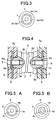
- a positive terminal 3a and a negative terminal 3b are protrusively provided on the respective ends of the battery module 3. As shown in FIG. 3, both terminals 3a and 3b are formed in circular shapes of the same diameter with screw holes 3c and 3d respectively threaded in their center portions.
- the battery case 1 has a case body 5 with the top and bottom and lengthwise sides open, and left and right end plates 6 attached to the associated, open lengthwise sides.
- Partitions 5a are arranged at predetermined pitches in the case body 5.
- Insertion holes 5b for holding the individual battery modules 3 abreast are bored through each partition 5a at predetermined positions.
- pass bars 8 which connect the cells 2 between the terminal 3a and 3b of each battery module 3 are inserted in the end plates 6 and 7 which are formed by resin molding.
- Circular recessed terminal receiving portions 6a and 7a in which the terminals 3a and 3b of each battery module 3 are to be respectively fitted are formed in the inner walls of the end plates 6 and 7 at positions corresponding to those terminals 3a and 3b.
- Fastening recesses 6b and 7b which receive the heads of bolts 9 are formed in the outer walls of the end plates 6 and 7 at positions corresponding to the recessed terminal receiving portions 6a and 7a.
- Insertion holes 8a through which the bolts 9 are inserted are formed in each pass bar 8 located between the terminal receiving portion 6a (7a) and the associated fastening recess 6b (7b).
- the removed end plate 7 (6) is secured to the open side of the battery case 5 and the terminal 3b (3a) protruding from the rear end of the battery module 3 is fitted in the recessed terminal receiving portion 7a (6a) formed in the end plate 7 (6).
- both terminals 3a and 3b have circular shapes of the same diameter, the positional alignment in the axial rotational direction is unnecessary at this time, resulting in an excellent workability.
- the bolts 9 are driven into the screw holes 3c and 3d, formed in the terminals 3a and 3b, through the insertion holes 8a formed in the pass bars 8 that are inserted in the end plates 6 and 7, thereby fastening the terminals 3a and 3b to the pass bars 8.
- each battery module 3 is designed to have circular shapes of the same diameter in this embodiment, no positional alignment in the axial rotational direction is needed at the time of fitting the terminals 3a and 3b to the end plates 6 and 7. This can ensure a higher workability and reduce the number of assembling steps. It is therefore possible to eliminate the need for the accurate angular alignment in the axial rotational direction prior to the attachment and facilitate automation of the assembling work. This automation can lead to a significant reduction in the number of assembling steps.
- FIGS. 5A and 5B show the second embodiment of this invention, which is a modification of the first embodiment and wherein the positive and negative terminals 3a and 3b are formed to have different diameters.
- the positive and negative terminals 3a and 3b have the same diameter, those terminals 3a and 3b may be attached to the wrong sides at the time of attaching each battery module to the battery case.
- the terminals 3a and 3b are so designed as to have different diameters in the second embodiment.
- the diameter of the negative terminal 3b is made smaller than that of the positive terminal 3a and the diameters of the recessed terminal receiving portions 6a and 7a formed in the end plates 6 and 7 are modified to match with those of the respective terminals 3a and 3b.
- the positive terminal 3a will not be fitted in the recessed terminal receiving portion 7a because of the diameter of the terminal receiving portion 7a being smaller than that of the positive terminal 3a. This can therefore prevent misattachment of both terminals of each battery module.
- the diameters of both terminals 3a and 3b are so set as to be distinguished from each other at a glance.
- FIG. 6 shows the third embodiment of this invention.
- This embodiment is a further modification of the first embodiment wherein both terminals 3a and 3b are formed to have the same regular polygonal shape, such as an octagonal shape, and the recessed terminal receiving portions 6a and 7a in which the terminals 3a and 3b are to be fitted are designed to have shapes corresponding to those of the terminals 3a and 3b.
- both terminals 3a and 3b have regular polygonal shapes and the recessed terminal receiving portions 6a and 7a in which the terminals 3a and 3b are to be fitted have corresponding polygonal shapes
- the positional alignment of the battery module 3 in the axial rotational direction can be carried out every rotational angle defined by the number of polygons of the regular polygonal shape. Further, this particular shape can serve to stop the rotation of the terminals 3a and 3b fitted in the recessed terminal receiving portions 6a and 7a at the time they are fastened by the bolts.
- FIGS. 7A and 7B show the fourth embodiment of this invention.
- FIG. 7A is a front view of the positive terminal 3a
- FIG. 7B a front view of the negative terminal 3b.
- This embodiment is a modification of the third embodiment wherein the polygonal positive and negative terminals 3a and 3b have similar shapes.
- the negative terminal 3b has a smaller shape than the positive terminal 3b.
- Designing terminals 3a and 3b to have similar shapes can prevent the larger terminal 3a from being fitted in the smaller recessed terminal receiving portion 7a, thereby inhibiting misattachment of both terminals 3a and 3b of each battery module. It is to be noted that the shapes of both terminals 3a and 3b are so designed as to be distinguished from each other at a glance.
- FIGS. 8A and 8B show the fifth embodiment of this invention.
- FIG. 8A is a front view of the positive terminal 3a
- FIG. 8B a front view of the negative terminal 3b.
- This embodiment is a modification of the fourth embodiment wherein the diameters of the screw holes 3c and 3d which are to be threaded in the respective terminals 3a and 3b differ from each other in such a way that the screw hole 3c for the larger terminal 3a is made smaller than the screw hole 3d for the smaller terminal 3b. Further, the insertion holes 8a formed in the pass bars 8 have dimensions corresponding to the associated screw holes 3c and 3d.
- the diameter of the screw hole 3d becomes larger than the diameter of the mating insertion holes 8a so that the misattachment can be quickly detected at a glance.
- FIG. 9 is a perspective view showing the recessed terminal receiving portion 6a (7a) according to the sixth embodiment of this invention.
- This embodiment is a modification of the second to fourth embodiments wherein terminal guide faces 10 are formed at the opening portion of the recessed terminal receiving portion 6a (7a).
- the recessed terminal receiving portion 6a (7a) has a square shape in this embodiment, this shape is not restrictive and can be any regular polygonal shape.
- Each terminal guide face 10 rises in a slope while spreading from the associated corner portion of the recessed terminal receiving portion 6a (7a), so that a ridge line is formed between the terminal guide face 10 and the adjoining terminal guide face 10 at the opening portion of the recessed terminal receiving portion 6a (7a).
- the corners of the terminal abut on the terminal guide faces 10 and rotate along the slopes to be fitted in the recessed terminal receiving portion 6a (7a).
- the positive and negative terminals formed at the respect ends of each battery module are designed to have same or similar shapes, so that when one terminal is fitted to the terminal receiving portion formed in the mating end plate at the time of attaching this battery module to the battery case, the other terminal is always fitted in the terminal receiving portion formed in the other end plate.
- This can improve the workability and reduce the number of assembling steps.
- the accurate angular alignment in the axial rotational direction prior to the attachment becomes easier, thus facilitating automation of the assembling work, which can significantly decrease the number of assembling steps.
- each battery module is made to have regular polygonal shapes, it is possible to make the positional alignment in the axial rotational direction every rotational angle defined by the number of polygons of the regular polygonal shape at the time of attaching the battery module to the battery case.
- the positive and negative terminals formed at the respect ends of each battery module are designed to have similar shapes and the terminal receiving portions provided on the end plates are designed to match with the shape of the larger terminal. Therefore, the positional alignment can be accomplished merely by fitting the larger terminal of the battery module into the terminal receiving portion provided on the mating end plate. This can ensure an excellent workability.
- screw holes of different diameters are threaded in the terminals provided at the respective ends of each battery module and insertion holes which match with the screw holes are formed in the terminal receiving portions at the positions where the end faces of the terminals abut. This allows a work to adequately grasp the alignment of the terminals of the battery module with the associated terminal receiving portions provided on the end plates.
- both terminals are designed to have similar shapes and a screw hole which has a larger diameter is threaded in the smaller terminal and a screw hole which has a smaller diameter is threaded in the larger terminal, it becomes possible to allow a worker to easily and visually confirm the direction of the attachment of the terminals of each battery module. This can further improve the assembling efficiency.
Landscapes
- Chemical & Material Sciences (AREA)
- Chemical Kinetics & Catalysis (AREA)
- Electrochemistry (AREA)
- General Chemical & Material Sciences (AREA)
- Connection Of Batteries Or Terminals (AREA)
- Battery Mounting, Suspending (AREA)
Abstract
Description
- The present invention relates to a battery power supply in which its battery modules can easily be attached to the battery case.
- There is a known battery power supply which is used as a motor driving power supply for an electric vehicle or a hybrid vehicle. This battery power supply comprises multiple battery modules each of which has a line of cells electrically and mechanically connected together in series and which are housed in a battery case and are electrically connected in series to provide the necessary voltage and current.
- With regard to such prior art, for example, Japanese Unexamined Patent Publication (KOKAI) No. 10-270006 discloses a technique of designing terminals at both ends of each battery module to have polygonal shapes with different numbers of polygons or forming recessed terminal receiving portions with the same shapes in which the terminals are fitted, thereby preventing misattachment of the positive and negative terminals at the time of attaching the battery modules to the battery case.
- According to the prior art, the positive terminal of each battery module has a square shape and the negative terminal has a regular hexagonal shape. Even with one terminal fitted into the recessed terminal receiving portion of the associated end plate, therefore, the other terminal may not be fitted in the recessed terminal receiving portion of the associated end plate.
- Specifically, as the positive terminal has a square shape, the angle of fitting becomes 90°, whereas the negative terminal has a hexagonal shape so that the fitting angle becomes 60°. Therefore, the position where both terminals can be fitted at the same time is limited to once every 180° and necessitates that both terminals should be fitted at the time of attaching the battery modules to the battery case while checking the rotational angles of the terminals. This makes the assembling work troublesome, thus leading to a poor working efficiency, and makes the automation of the assembling work difficult to achieve.
- Accordingly, it is an object of the present invention to provide a battery power supply which facilitates the attachment of the battery modules to the battery case without misattachment of both terminals of each battery module, reduces the number of assembling steps and ensures an easier automation of the assembling work.
- To achieve the above object, according to the first aspect of this invention, there is provided A battery power supply comprising battery modules each having a plurality of cells electrically and mechanically connected together in a line; a battery case for holding the battery modules; end plates, respectively provided at both end portions of the battery case, for electrically connecting positive and negative terminals provided at both ends of each of the battery modules, the positive and negative terminals having same or similar shapes; and terminal receiving portions which are provided at the end plates and in which the positive and negative terminals at the both ends of each of the battery modules are fitted.
- According to the battery power supply of the first aspect of this invention, the positive and negative terminals of each of the battery modules may have circular shapes.
- According to the battery power supply of the first aspect of this invention, the positive and negative terminals of each of the battery modules may have regular polygonal shapes.
- According to any of the above-described battery power supplies, a guide face for guiding at least one of the positive and negative terminals of each of the battery modules may be formed at an insertion mouth of the associated terminal receiving portion.
- According to the second aspect of this invention, there is provided a battery power supply comprising battery modules each having a plurality of cells electrically and mechanically connected together in a line; a battery case for holding the battery modules; end plates, respectively provided at both end portions of the battery case, for electrically connecting positive and negative terminals provided at both ends of each of the battery modules, the positive and negative terminals having similar shapes; and terminal receiving portions, provided at the end plates, for receiving the positive and negative terminals of each of the battery modules, the terminal receiving portions having shapes matched with that of a larger one of the positive and negative terminals.
- According to the battery power supply of the second aspect of this invention, a guide face for guiding at least one of the positive and negative terminals of each of the battery modules may be formed at an insertion mouth of the associated terminal receiving portion.
- In any of the battery power supplies associated with the first aspect of this invention, screw holes of different diameters are formed in end faces of the positive and negative terminals provided at the both ends of each of the battery modules; and insertion holes matched with the screw holes are bored in the terminal receiving portions on which the end faces of the positive and negative terminals abut. In this case, the positive and negative terminals of each of the battery modules have similar shapes; that one of the screw holes which has a larger diameter is formed in the end face of that one of the positive and negative terminals which has a smaller shape; and the other screw hole which has a smaller diameter is formed in the end face of the other one of the positive and negative terminals which has a larger shape.
- In any of the battery power supplies associated with the second aspect of this invention, screw holes of different diameters may be formed in end faces of the positive and negative terminals provided at the both ends of each of the battery modules; and insertion holes matched with the screw holes are bored in the terminal receiving portions on which the end faces of the positive and negative terminals abut. In this case, that one of the screw holes which has a larger diameter is formed in the end face of that one of the positive and negative terminals which has a smaller shape; and the other screw hole which has a smaller diameter is formed in the end face of the other one of the positive and negative terminals which has a larger shape.
-
- FIG. 1 is a perspective view of a battery case according to a first embodiment of this invention;
- FIG. 2 is a plan view of battery modules according to the first embodiment;
- FIG. 3 is a side view showing terminals provided on each battery module according to the first embodiment;
- FIG. 4 is a partly cross-sectional plan view showing the battery modules secured to end plates according to the first embodiment;
- FIGS. 5A and 5B front views of terminals provided on a battery module according to a second embodiment of this invention;
- FIG. 6 is a front view of terminals provided on a battery module according to a third embodiment of this invention;
- FIGS. 7A and 7B are front views of terminals provided on a battery module according to a fourth embodiment of this invention;
- FIGS. 8A and 8B are front views of terminals provided on a battery module according to a fifth embodiment of this invention; and
- FIG. 9 is a perspective view showing recessed terminal receiving portions according to a sixth embodiment of this invention.
-
- Preferred embodiments of the present invention will now be described with reference to the accompanying drawings.
- FIGS. 1 through 4 illustrate the first embodiment of this invention.
- FIG. 1 is a perspective view of a battery power supply A according to the first embodiment, which is to be installed in an electric vehicle, a hybrid vehicle or the like. This battery power supply A has a
battery case 1 which accommodates a power source for driving an electric motor. - As the power source, a secondary battery of, for example, a nickel-hydrogen battery is used. The
battery case 1 accommodates a plurality of battery modules 3 (5 x 3 battery modules in this embodiment) arranged abreast, each having a line of cells 2 (unit cells of the secondary battery) electrically and mechanically connected together in series. Theindividual battery modules 3 are connected in series to one another, so that a high voltage can be supplied to an electric motor. - The outer surface of each
battery module 3 is covered with an armor tube (not shown) of a resin of polyvinyl chloride or the like, which has a dielectric and thermal shrinking property. Apositive terminal 3a and anegative terminal 3b are protrusively provided on the respective ends of thebattery module 3. As shown in FIG. 3, bothterminals screw holes - The
battery case 1 has acase body 5 with the top and bottom and lengthwise sides open, and left andright end plates 6 attached to the associated, open lengthwise sides. Partitions 5a are arranged at predetermined pitches in thecase body 5. Insertion holes 5b for holding theindividual battery modules 3 abreast are bored through each partition 5a at predetermined positions. - As shown in FIG. 4,
pass bars 8 which connect thecells 2 between theterminal battery module 3 are inserted in theend plates portions terminals battery module 3 are to be respectively fitted are formed in the inner walls of theend plates terminals recesses bolts 9 are formed in the outer walls of theend plates terminal receiving portions Insertion holes 8a through which thebolts 9 are inserted are formed in eachpass bar 8 located between theterminal receiving portion 6a (7a) and the associated fastening recess 6b (7b). - The assembling of the battery power supply A according to this embodiment will now be described. First, one of the
end plates battery case 5 to open one side of thebattery case 5. For easier understanding of the work, let us assume that theend plate 7 is removed. Eachbattery module 3 is put inside thebattery case 5 from the open side and is inserted through the insertion holes 5b formed in the partitions 5a and theterminal 3a (3b) protruding from the distal end of thebattery module 3 is fitted in the recessedterminal receiving portion 6a (7a) formed in the end plate 6 (7) that is secured to the opposite side of thebattery case 5. - Thereafter, the removed end plate 7 (6) is secured to the open side of the
battery case 5 and theterminal 3b (3a) protruding from the rear end of thebattery module 3 is fitted in the recessedterminal receiving portion 7a (6a) formed in the end plate 7 (6). - As both
terminals - Then, the
bolts 9 are driven into thescrew holes terminals insertion holes 8a formed in thepass bars 8 that are inserted in theend plates terminals pass bars 8. - As apparent from the above, because the
positive terminal 3a andnegative terminal 3b at the respect ends of eachbattery module 3 are designed to have circular shapes of the same diameter in this embodiment, no positional alignment in the axial rotational direction is needed at the time of fitting theterminals end plates - FIGS. 5A and 5B show the second embodiment of this invention, which is a modification of the first embodiment and wherein the positive and
negative terminals - If the positive and
negative terminals terminals terminals - Specifically, the diameter of the
negative terminal 3b is made smaller than that of thepositive terminal 3a and the diameters of the recessedterminal receiving portions end plates respective terminals positive terminal 3a in the recessedterminal receiving portion 7a formed in theright end plate 7, thepositive terminal 3a will not be fitted in the recessedterminal receiving portion 7a because of the diameter of theterminal receiving portion 7a being smaller than that of thepositive terminal 3a. This can therefore prevent misattachment of both terminals of each battery module. - The diameters of both
terminals - FIG. 6 shows the third embodiment of this invention. This embodiment is a further modification of the first embodiment wherein both
terminals terminal receiving portions terminals terminals - As both
terminals terminal receiving portions terminals battery module 3 in the axial rotational direction can be carried out every rotational angle defined by the number of polygons of the regular polygonal shape. Further, this particular shape can serve to stop the rotation of theterminals terminal receiving portions - FIGS. 7A and 7B show the fourth embodiment of this invention. FIG. 7A is a front view of the
positive terminal 3a, and FIG. 7B a front view of thenegative terminal 3b. - This embodiment is a modification of the third embodiment wherein the polygonal positive and
negative terminals negative terminal 3b has a smaller shape than thepositive terminal 3b. - Designing
terminals terminal receiving portion 7a, thereby inhibiting misattachment of bothterminals terminals - FIGS. 8A and 8B show the fifth embodiment of this invention. FIG. 8A is a front view of the
positive terminal 3a, and FIG. 8B a front view of thenegative terminal 3b. - This embodiment is a modification of the fourth embodiment wherein the diameters of the screw holes 3c and 3d which are to be threaded in the
respective terminals screw hole 3c for thelarger terminal 3a is made smaller than thescrew hole 3d for thesmaller terminal 3b. Further, theinsertion holes 8a formed in the pass bars 8 have dimensions corresponding to the associated screw holes 3c and 3d. - According to this embodiment, if the
smaller terminal 3b is erroneously fitted in the larger recessedterminal receiving portion 6a, the diameter of thescrew hole 3d becomes larger than the diameter of themating insertion holes 8a so that the misattachment can be quickly detected at a glance. - FIG. 9 is a perspective view showing the recessed
terminal receiving portion 6a (7a) according to the sixth embodiment of this invention. This embodiment is a modification of the second to fourth embodiments wherein terminal guide faces 10 are formed at the opening portion of the recessedterminal receiving portion 6a (7a). - Although the recessed
terminal receiving portion 6a (7a) has a square shape in this embodiment, this shape is not restrictive and can be any regular polygonal shape. - Each terminal guide face 10 rises in a slope while spreading from the associated corner portion of the recessed
terminal receiving portion 6a (7a), so that a ridge line is formed between theterminal guide face 10 and the adjoining terminal guide face 10 at the opening portion of the recessedterminal receiving portion 6a (7a). - According to this embodiment, if the axial rotational direction of the terminal having a square shape is not aligned with the recessed
terminal receiving portion 6a (7a) when the terminals formed at the both ends of each battery module put closer to the recessedterminal receiving portions terminal receiving portion 6a (7a). - Even if the terminals of each battery module are not aligned with the recessed
terminal receiving portions - According to one aspect of this invention, as described above, the positive and negative terminals formed at the respect ends of each battery module are designed to have same or similar shapes, so that when one terminal is fitted to the terminal receiving portion formed in the mating end plate at the time of attaching this battery module to the battery case, the other terminal is always fitted in the terminal receiving portion formed in the other end plate. This can improve the workability and reduce the number of assembling steps. Further, the accurate angular alignment in the axial rotational direction prior to the attachment becomes easier, thus facilitating automation of the assembling work, which can significantly decrease the number of assembling steps.
- In this case, if the shapes of the terminals provided at both ends of each battery module are made circular, it is possible to eliminate the need for the positional alignment in the axial rotational direction at the time of attaching the battery module to the battery case. This ensures a higher workability.
- If the terminals provided at both ends of each battery module are made to have regular polygonal shapes, it is possible to make the positional alignment in the axial rotational direction every rotational angle defined by the number of polygons of the regular polygonal shape at the time of attaching the battery module to the battery case.
- According to one modification, the positive and negative terminals formed at the respect ends of each battery module are designed to have similar shapes and the terminal receiving portions provided on the end plates are designed to match with the shape of the larger terminal. Therefore, the positional alignment can be accomplished merely by fitting the larger terminal of the battery module into the terminal receiving portion provided on the mating end plate. This can ensure an excellent workability.
- In this case, if a guide face for guiding at least one of the positive and negative terminals provided at the respective ends of each battery module is formed at the insertion mouth of the associated terminal receiving portion, the terminal is guided along the guide surface to the associated terminal receiving portion at the time of attaching the battery module to the battery case. This ensures a higher workability.
- According to another modification, screw holes of different diameters are threaded in the terminals provided at the respective ends of each battery module and insertion holes which match with the screw holes are formed in the terminal receiving portions at the positions where the end faces of the terminals abut. This allows a work to adequately grasp the alignment of the terminals of the battery module with the associated terminal receiving portions provided on the end plates.
- In this case, if both terminals are designed to have similar shapes and a screw hole which has a larger diameter is threaded in the smaller terminal and a screw hole which has a smaller diameter is threaded in the larger terminal, it becomes possible to allow a worker to easily and visually confirm the direction of the attachment of the terminals of each battery module. This can further improve the assembling efficiency.
- Although several embodiments of the present invention have been described herein, it should be apparent to those skilled in the art that the present examples and embodiments are to be considered as illustrative and not restrictive and the invention is not to be limited to the details given herein, but may be modified within the scope of the appended claims.
Claims (10)
- A battery power supply comprising:battery modules each having a plurality of cells electrically and mechanically connected together in a line;a battery case for holding said battery modules;end plates, respectively provided at both end portions of said battery case, for electrically connecting positive and negative terminals provided at both ends of each of said battery modules, said positive and negative terminals having same or similar shapes; andterminal receiving portions which are provided at said end plates and in which said positive and negative terminals at said both ends of each of said battery modules are fitted.
- The battery power supply according to claim 1, wherein said positive and negative terminals of each of said battery modules have circular shapes.
- The battery power supply according to claim 1, wherein said positive and negative terminals of each of said battery modules have regular polygonal shapes.
- The battery power supply according to any one of claims 1 to 3, wherein a guide face for guiding at least one of said positive and negative terminals of each of said battery modules is formed at an insertion mouth of the associated terminal receiving portion.
- A battery power supply comprising:battery modules each having a plurality of cells electrically and mechanically connected together in a line;a battery case for holding said battery modules;end plates, respectively provided at both end portions of said battery case, for electrically connecting positive and negative terminals provided at both ends of each of said battery modules, said positive and negative terminals having similar shapes; andterminal receiving portions, provided at said end plates, for receiving said positive and negative terminals of each of said battery modules, said terminal receiving portions having shapes matched with that of a larger one of said positive and negative terminals.
- The battery power supply according to claim 5, wherein a guide face for guiding at least one of said positive and negative terminals of each of said battery modules is formed at an insertion mouth of the associated terminal receiving portion.
- The battery power supply according to any one of claims 1 to 4, wherein screw holes of different diameters are formed in end faces of said positive and negative terminals provided at said both ends of each of said battery modules; andinsertion holes matched with said screw holes are bored in said terminal receiving portions on which said end faces of said positive and negative terminals abut.
- The battery power supply according to claim 5 or 6, wherein screw holes of different diameters are formed in end faces of said positive and negative terminals provided at said both ends of each of said battery modules; andinsertion holes matched with said screw holes are bored in said terminal receiving portions on which said end faces of said positive and negative terminals abut.
- The battery power supply according to claim 7, wherein said positive and negative terminals of each of said battery modules have similar shapes;that one of said screw holes which has a larger diameter is formed in the end face of that one of said positive and negative terminals which has a smaller shape; andthe other screw hole which has a smaller diameter is formed in the end face of the other one of said positive and negative terminals which has a larger shape.
- The battery power supply according to claim 8, wherein that one of said screw holes which has a larger diameter is formed in the end face of that one of said positive and negative terminals which has a smaller shape; andthe other screw hole which has a smaller diameter is formed in the end face of the other one of said positive and negative terminals which has a larger shape.
Applications Claiming Priority (2)
| Application Number | Priority Date | Filing Date | Title |
|---|---|---|---|
| JP11709899 | 1999-04-23 | ||
| JP11709899A JP4425369B2 (en) | 1999-04-23 | 1999-04-23 | Battery power supply |
Publications (2)
| Publication Number | Publication Date |
|---|---|
| EP1047138A1 true EP1047138A1 (en) | 2000-10-25 |
| EP1047138B1 EP1047138B1 (en) | 2005-09-07 |
Family
ID=14703360
Family Applications (1)
| Application Number | Title | Priority Date | Filing Date |
|---|---|---|---|
| EP00108645A Expired - Lifetime EP1047138B1 (en) | 1999-04-23 | 2000-04-20 | Battery power supply |
Country Status (4)
| Country | Link |
|---|---|
| US (1) | US6489747B2 (en) |
| EP (1) | EP1047138B1 (en) |
| JP (1) | JP4425369B2 (en) |
| DE (1) | DE60022423T2 (en) |
Cited By (2)
| Publication number | Priority date | Publication date | Assignee | Title |
|---|---|---|---|---|
| EP1458049A4 (en) * | 2001-11-01 | 2006-04-19 | Honda Motor Co Ltd | Battery-driven power source apparatus |
| WO2010102855A1 (en) * | 2009-03-12 | 2010-09-16 | Robert Bosch Gmbh | Battery system having an output voltage of more than 60 v direct current voltage |
Families Citing this family (16)
| Publication number | Priority date | Publication date | Assignee | Title |
|---|---|---|---|---|
| JP4626034B2 (en) * | 2000-09-08 | 2011-02-02 | パナソニック株式会社 | Collective sealed secondary battery |
| US20040044448A1 (en) * | 2002-08-27 | 2004-03-04 | Ford Motor Company | Vehicle systems controller with modular architecture |
| US6657414B1 (en) * | 2003-02-27 | 2003-12-02 | Merits Health Products Co., Ltd. | Terminal device for a battery container on an electromobile |
| USD504395S1 (en) * | 2003-05-07 | 2005-04-26 | Milwaukee Electric Tool Corporation | Battery charger |
| US20050064785A1 (en) * | 2003-09-16 | 2005-03-24 | New Bright Industrial Co., Ltd. | High performance rechargeable battery pack for toy vehicles |
| US20060110630A1 (en) * | 2004-11-23 | 2006-05-25 | Michael Herman | Battery with integrated screwdriver |
| US7967506B2 (en) * | 2005-03-16 | 2011-06-28 | Ford Global Technologies, Llc | Power supply temperature sensor and system |
| US7604896B2 (en) | 2005-03-16 | 2009-10-20 | Ford Global Technologies, Llc | High voltage battery assembly for a motor vehicle |
| CN2819483Y (en) * | 2005-04-15 | 2006-09-20 | 金达时发展有限公司 | Combinable connecting frame for thin-plate lithium battery |
| JP5003137B2 (en) * | 2006-12-15 | 2012-08-15 | カシオ計算機株式会社 | Power generation module |
| KR101140449B1 (en) * | 2007-09-19 | 2012-04-30 | 에스케이이노베이션 주식회사 | Module pack For Secondary Battery |
| WO2011151838A1 (en) * | 2010-06-02 | 2011-12-08 | Anil Ananthakrishna | A multi-terminal battery plate |
| KR20140089979A (en) | 2013-01-08 | 2014-07-16 | 삼성에스디아이 주식회사 | Battery module |
| CN209150238U (en) * | 2019-06-21 | 2019-07-23 | 比亚迪股份有限公司 | Battery modules, power battery packs and vehicles |
| TWM594276U (en) * | 2019-12-16 | 2020-04-21 | 財團法人工業技術研究院 | Battery module |
| US11502363B2 (en) * | 2020-01-22 | 2022-11-15 | Toyota Motor Engineering & Manufacturing North America Inc. | Terminal rail connector on battery stack sides for bus bar module removal |
Citations (1)
| Publication number | Priority date | Publication date | Assignee | Title |
|---|---|---|---|---|
| JPH10270006A (en) * | 1997-03-24 | 1998-10-09 | Toyota Motor Corp | Battery power supply and end plate used for it |
Family Cites Families (10)
| Publication number | Priority date | Publication date | Assignee | Title |
|---|---|---|---|---|
| FR2344133A1 (en) * | 1976-03-09 | 1977-10-07 | Accumulateurs Fixes | ACCUMULATOR BATTERY CHASSIS |
| US5227267A (en) * | 1990-11-01 | 1993-07-13 | Yardney Technical Products, Inc. | Disc electrode and busbar for an electrochemical battery |
| US5200280A (en) * | 1991-09-05 | 1993-04-06 | Black & Decker Inc. | Terminal cover for a battery pack |
| JPH08250151A (en) * | 1995-03-14 | 1996-09-27 | Matsushita Electric Ind Co Ltd | Unit battery of sealed alkaline storage battery |
| JP3271495B2 (en) * | 1995-10-24 | 2002-04-02 | 松下電器産業株式会社 | Battery pack |
| JP3271494B2 (en) * | 1995-10-24 | 2002-04-02 | 松下電器産業株式会社 | Stacked sealed alkaline storage battery |
| EP0892450B1 (en) * | 1997-03-24 | 2004-05-12 | Matsushita Electric Industrial Co., Ltd. | Battery power source unit |
| US5886501A (en) * | 1997-04-07 | 1999-03-23 | General Motors Corporation | Battery pack electrical interconnects |
| US6186831B1 (en) * | 1999-06-08 | 2001-02-13 | Real Power Cap Company | Link bar for capacitors of audio system |
| US6097173A (en) * | 1999-09-29 | 2000-08-01 | Bryant, Jr.; Olen Winters | Solid bar battery strap assembly |
-
1999
- 1999-04-23 JP JP11709899A patent/JP4425369B2/en not_active Expired - Fee Related
-
2000
- 2000-04-20 DE DE60022423T patent/DE60022423T2/en not_active Expired - Lifetime
- 2000-04-20 EP EP00108645A patent/EP1047138B1/en not_active Expired - Lifetime
- 2000-04-24 US US09/556,633 patent/US6489747B2/en not_active Expired - Fee Related
Patent Citations (1)
| Publication number | Priority date | Publication date | Assignee | Title |
|---|---|---|---|---|
| JPH10270006A (en) * | 1997-03-24 | 1998-10-09 | Toyota Motor Corp | Battery power supply and end plate used for it |
Non-Patent Citations (1)
| Title |
|---|
| PATENT ABSTRACTS OF JAPAN vol. 1999, no. 01 29 January 1999 (1999-01-29) * |
Cited By (3)
| Publication number | Priority date | Publication date | Assignee | Title |
|---|---|---|---|---|
| EP1458049A4 (en) * | 2001-11-01 | 2006-04-19 | Honda Motor Co Ltd | Battery-driven power source apparatus |
| US7261974B2 (en) | 2001-11-01 | 2007-08-28 | Honda Giken Kogyo Kabushiki Kaisha | Battery-driven power source apparatus |
| WO2010102855A1 (en) * | 2009-03-12 | 2010-09-16 | Robert Bosch Gmbh | Battery system having an output voltage of more than 60 v direct current voltage |
Also Published As
| Publication number | Publication date |
|---|---|
| JP2000306561A (en) | 2000-11-02 |
| DE60022423T2 (en) | 2006-06-29 |
| DE60022423D1 (en) | 2005-10-13 |
| EP1047138B1 (en) | 2005-09-07 |
| US6489747B2 (en) | 2002-12-03 |
| JP4425369B2 (en) | 2010-03-03 |
| US20020070704A1 (en) | 2002-06-13 |
Similar Documents
| Publication | Publication Date | Title |
|---|---|---|
| EP1047138B1 (en) | Battery power supply | |
| US9397327B2 (en) | Battery connecting assembly | |
| US9425520B2 (en) | Battery wiring module | |
| US9209550B2 (en) | Battery wiring module | |
| EP2144332B1 (en) | A connector, a connector assembly and a connecting method | |
| KR100358618B1 (en) | Battery power supply apparatus | |
| US9905832B2 (en) | Battery wiring module | |
| JP5862077B2 (en) | Battery wiring module | |
| KR20120048259A (en) | Battery module | |
| US11329350B2 (en) | Bus bar module and method for assembling bus bar module | |
| US6786777B2 (en) | Split-type connector | |
| CN207559179U (en) | Connector for bus bar connection and battery pack including the connector | |
| US20110198121A1 (en) | Assembly of case and electronic components and combination of the assembly and external connectors | |
| US6523274B1 (en) | Unit assembling error prevention structure | |
| US20190221787A1 (en) | Connection module cover and connection module | |
| US20190198842A1 (en) | Connection module | |
| EP2804238A1 (en) | Wiring module | |
| JPH06318479A (en) | Electrical contact block and connector using the same | |
| JP2002027675A (en) | Storage battery for power tools | |
| US5611712A (en) | Connector with terminal stopper attached and method for inserting and stopping terminal fittings using same | |
| JP2025188255A (en) | Wiring Module | |
| CN112448091A (en) | Battery wiring module | |
| KR20240134597A (en) | Battery Cell Stack Assembly and The Battery Module Including The Same | |
| CN223245989U (en) | Connecting device suitable for battery pack | |
| US20250096428A1 (en) | Battery |
Legal Events
| Date | Code | Title | Description |
|---|---|---|---|
| PUAI | Public reference made under article 153(3) epc to a published international application that has entered the european phase |
Free format text: ORIGINAL CODE: 0009012 |
|
| AK | Designated contracting states |
Kind code of ref document: A1 Designated state(s): DE GB |
|
| AX | Request for extension of the european patent |
Free format text: AL;LT;LV;MK;RO;SI |
|
| 17P | Request for examination filed |
Effective date: 20010425 |
|
| AKX | Designation fees paid |
Free format text: DE GB |
|
| 17Q | First examination report despatched |
Effective date: 20031114 |
|
| GRAP | Despatch of communication of intention to grant a patent |
Free format text: ORIGINAL CODE: EPIDOSNIGR1 |
|
| GRAS | Grant fee paid |
Free format text: ORIGINAL CODE: EPIDOSNIGR3 |
|
| GRAA | (expected) grant |
Free format text: ORIGINAL CODE: 0009210 |
|
| AK | Designated contracting states |
Kind code of ref document: B1 Designated state(s): DE GB |
|
| REG | Reference to a national code |
Ref country code: GB Ref legal event code: FG4D |
|
| REF | Corresponds to: |
Ref document number: 60022423 Country of ref document: DE Date of ref document: 20051013 Kind code of ref document: P |
|
| PLBE | No opposition filed within time limit |
Free format text: ORIGINAL CODE: 0009261 |
|
| STAA | Information on the status of an ep patent application or granted ep patent |
Free format text: STATUS: NO OPPOSITION FILED WITHIN TIME LIMIT |
|
| 26N | No opposition filed |
Effective date: 20060608 |
|
| PGFP | Annual fee paid to national office [announced via postgrant information from national office to epo] |
Ref country code: GB Payment date: 20090415 Year of fee payment: 10 |
|
| GBPC | Gb: european patent ceased through non-payment of renewal fee |
Effective date: 20100420 |
|
| PG25 | Lapsed in a contracting state [announced via postgrant information from national office to epo] |
Ref country code: GB Free format text: LAPSE BECAUSE OF NON-PAYMENT OF DUE FEES Effective date: 20100420 |
|
| PGFP | Annual fee paid to national office [announced via postgrant information from national office to epo] |
Ref country code: DE Payment date: 20160412 Year of fee payment: 17 |
|
| REG | Reference to a national code |
Ref country code: DE Ref legal event code: R082 Ref document number: 60022423 Country of ref document: DE Representative=s name: MEISSNER BOLTE PATENTANWAELTE RECHTSANWAELTE P, DE Ref country code: DE Ref legal event code: R081 Ref document number: 60022423 Country of ref document: DE Owner name: SUBARU CORPORATION, JP Free format text: FORMER OWNER: FUJI JUKOGYO K.K., TOKIO/TOKYO, JP |
|
| REG | Reference to a national code |
Ref country code: DE Ref legal event code: R119 Ref document number: 60022423 Country of ref document: DE |
|
| PG25 | Lapsed in a contracting state [announced via postgrant information from national office to epo] |
Ref country code: DE Free format text: LAPSE BECAUSE OF NON-PAYMENT OF DUE FEES Effective date: 20171103 |