EP1046930A2 - Process for improving the bit seismic signal using drilling parameters - Google Patents
Process for improving the bit seismic signal using drilling parameters Download PDFInfo
- Publication number
- EP1046930A2 EP1046930A2 EP00201332A EP00201332A EP1046930A2 EP 1046930 A2 EP1046930 A2 EP 1046930A2 EP 00201332 A EP00201332 A EP 00201332A EP 00201332 A EP00201332 A EP 00201332A EP 1046930 A2 EP1046930 A2 EP 1046930A2
- Authority
- EP
- European Patent Office
- Prior art keywords
- signal
- tracks
- drilling
- seismic
- noise
- Prior art date
- Legal status (The legal status is an assumption and is not a legal conclusion. Google has not performed a legal analysis and makes no representation as to the accuracy of the status listed.)
- Granted
Links
Images



Classifications
-
- G—PHYSICS
- G01—MEASURING; TESTING
- G01V—GEOPHYSICS; GRAVITATIONAL MEASUREMENTS; DETECTING MASSES OR OBJECTS; TAGS
- G01V1/00—Seismology; Seismic or acoustic prospecting or detecting
- G01V1/40—Seismology; Seismic or acoustic prospecting or detecting specially adapted for well-logging
- G01V1/42—Seismology; Seismic or acoustic prospecting or detecting specially adapted for well-logging using generators in one well and receivers elsewhere or vice versa
-
- G—PHYSICS
- G01—MEASURING; TESTING
- G01V—GEOPHYSICS; GRAVITATIONAL MEASUREMENTS; DETECTING MASSES OR OBJECTS; TAGS
- G01V1/00—Seismology; Seismic or acoustic prospecting or detecting
- G01V1/28—Processing seismic data, e.g. for interpretation or for event detection
- G01V1/36—Effecting static or dynamic corrections on records, e.g. correcting spread; Correlating seismic signals; Eliminating effects of unwanted energy
- G01V1/362—Effecting static or dynamic corrections; Stacking
-
- G—PHYSICS
- G01—MEASURING; TESTING
- G01V—GEOPHYSICS; GRAVITATIONAL MEASUREMENTS; DETECTING MASSES OR OBJECTS; TAGS
- G01V2210/00—Details of seismic processing or analysis
- G01V2210/10—Aspects of acoustic signal generation or detection
- G01V2210/16—Survey configurations
- G01V2210/161—Vertical seismic profiling [VSP]
Definitions
- the present invention relates to a process for improving the Signal/Noise ratio in the preparation of vertical seismic profiles (VSP) which supply information on subsoil geological formations to be subjected to drilling, using as seismic source the vibrations produced by the drilling bit.
- VSP vertical seismic profiles
- this technique by means of signal reflections on lithologic formation layers, provides a representation of the subsoil adjacent to the drilling well. The position of the various subsoil layers is reconstructed on the basis of the delay times with which the signals return to the receivers.
- the conventional VSP prospecting method involves interrupting the drilling operation, extracting the drill-string and the bit, introducing one or more geophone detectors into the drilled well and generating on the surface, or at low depths and close to the well, one or more acoustic impulses (for example by exploding explosive charges) and measuring the signals which reach the geophones situated inside the well.
- This operating technique there are no doubts as to the primary signal generated on the surface, but there are considerable disadvantages. It is, in fact, very costly, also because it requires the interruption of the drilling operations for a long period of time and can therefore only be applied very few times during the drilling. Furthermore the extraction and reintroduction of the drilling battery is not without risks and therefore requires particular safety procedures and precautions.
- the use of the drilling bit itself as seismic source has the advantage of allowing surface measurements to be taken during the drilling without interfering with the field activities and collecting a large amount of data at a low cost and with low risks, with frequent or even continuous measurement campaigns.
- the signal generated by the bit has the disadvantage of being affected by propagation disturbances and becoming continuous over a period of time. It is therefore very difficult to establish which is the reliable signal generated by the bit to allow useful comparison with the return signals registered by the probes positioned on the ground surrounding the drilling well. For this reason the signal is continuously collected, checked and processed by means of specific on-site operating units ("while drilling" seismic cabin).
- the technical problem presented when using this method is the elimination, to the largest possible extent, of the noise component present in the seismic signal measurements of the bit.
- the Signal/Noise ratio can be improved using the technique of summing up the contribution of a large amount of data collected by the measuring probes over a reasonable period of time. Even this method however has its drawbacks. In fact, the duration of the time period over which the data can be summed up, is limited by the fact that the bit continues with time to penetrate deeper and deeper. There are consequently applicative limits of a practical nature; for example, the drilling of softer or less compact layers generates weaker signals and the measurements must be continued for longer times to enable them to be significant. In this case the drilling is faster and, owing to the excessive penetration of the bit during the measurement, there are limitations in the time duration so as not to lose space resolution.
- the disturbance often prevents a clear reception of the bit signal and can only be partially eliminated with the method of summing up the contribution of numerous measurements repeated over reasonable periods of time; the result which can be obtained is an improved, but still not sufficiently high, Signal/Noise ratio.
- the process of the present invention is based on the method of summing up by weight the contribution of numerous data collected by the measurement probes over a period of time. This is achieved by using coefficients which only amplify records having a high Signal/Noise ratio, and also separating the records which prevalently contain noise.
- the weighed sum is effected by analysis of the data selected and re-ordered according to various drilling parameters measured during the collection of the bit signal.
- the present invention relates to a process for improving the Signal/Noise ratio in the preparation of vertical seismic profiles (VSP) which provide information on the geological formations of the sub-soil to be subjected to drilling, using as a signal the vibrations produced by the drilling bit used as seismic source; an extremely representative measurement of the above signal (pilot signal) and the measurements of the signals transmitted into the ground and reflected on the layers (seismic signals) being effected by a series of receivers which form the seismic line, the above process comprising the practically simultaneous collection of:
- VSP vertical seismic profiles
- the parameters (B) which describe the instantaneous drilling state during the measurements (A), are collected at regular intervals during the drilling itself, for example every second. They can also be sub-sampled to supply information in the time interval relating to the single registration (A) of the group of multi-seismic recordings (A) collected for the same depth level.
- the time duration of the single registration (A) may, for example, be 24 seconds, and the average value of (B) will therefore be obtained on the corresponding 24 seconds; in this way there will be a characteristic description of the whole registration of 24 seconds during which the average value was calculated.
- Typical examples of drilling parameters are indicated in Table 1.
- Parameter Measurement unit Date Hour Depth meters Vertical depth meters Bit depth meters Kelly position meters ROP (Rate of Penetration) meters/hour RPM revs/minute WOB (weight on bit) Tons Hookland Tons Torque Kg/m Pump pressure Kg/cm 3 Mud in weight gr/l Mud out weight gr/l Flow in l/m Flow out l/m Pump tot l/m Bit distance m String length m String weight Tons
- the drilling parameters (B) used in the process of the present invention are those which describe the dynamic drilling conditions, for example torque, weight on bit (WOB), rate of penetration (ROP), rotation rate (RPM), mud flow (FLOW IN/OUT). Combinations of the above parameters can also be used.
- the criteria with which the most representative signals can be identified are based on the analysis of the organized (rearranged) data with the drilling parameters. It is thus possible to more effectively analyze the correspondences between the drilling parameters (B) and the signal and noise levels in the seismic data (A) obtained with the bit in the various operating contexts. From these correspondences, the criteria for improving the sum of the data collected for the same drilling level are determined, for example by summing up the correlations of different tens of registrations of 24 seconds obtained in a short penetration interval of the bit.
- FIG. 1 illustrates the rotary table system, as the means of activating the rotation of the battery of rods. This system however, as is known to experts in the field, is equivalent to the so-called "top drive” system.
- top drive the so-called "top drive” system.
- the process of the present invention comprises the following steps:
- the time (t) can be a discrete variable.
- the cross-relation and deconvolution are carried out using methods well-known to experts in the field, for example in frequencies.
- t PICK k direct arrival time of the signal in the seismic channel (k) or in the focalized track. Once the representative seismic channel index k has been established, this time is practically constant for the data of the same level acquired for a limited bit penetration (a few meters) and does therefore not depend on the index i.
- the re-arrangement is identified by i ⁇ --> h(i,j).
- channel number k is given by c ik (t) ----- > u hk (t), or c Aik (t) ----- > u Ahk (t).
- Phases 3 to 5 allow the evaluation of random noise levels (which is reduced in the sum), coherent noise levels (which can be reinforced in the sum) and signal levels, in groups of tracks selected with different arrangements in relation to the drilling parameters.
- the subsets ⁇ q can be selected in ranges defined by maximum and minimum values of the parameter itself.
- signal refers to the part near the direct arrival (which in aligned data is near the correlation zero), i.e. the part which has the maximum similitude between the datum registered by the pilot and the datum registered by the extension probe.
- the signal level is examined by measuring the energy in a suitably long time span, centered on the cross-correlation zero of the aligned signal, whereas the noise level is calculated, possibly after deconvolution, on suitably wide span for negative times of the aligned signal (anti-random part).
- this noise span there are both random noise and coherent noise components resulting from the cross-correlation operation.
- Step (6) consists in summing up, limited to the indexes ⁇ MAX of point (5), the data c hk (t) selected for the given drilling parameter for the level obtained. The sum is thus limited to measurements with the ⁇ MAX indexes which optimize the S/N ratio of point (5).
- the signal of the F channels is obtained:
- these weights can be selected so that 0 ⁇ ⁇ h ⁇ 1 is in relation to the parameter itself and therefore to S/N to optimize the sum with known methods.
- Step (7) refers to the possible calculation of the noise range with the partial or total range sum, the identification of the relative operating conditions and subsequent subtraction of the undesired signal from that selected with the optimum intersection.
- the optimum range and complementary range signal and noise are obtained with different amplitudes.
- Step (8) consists in the optional application of points 1-7 (or 1 to 6) at all drilling levels reached.
- the process of the present invention has many advantages with respect to the processes of the prior art.
- the process of the present invention is particularly advantageous with data in which the direct identification of the Signal/Noise ratio is not always possible, but can be associated with significant drilling conditions. This allows the final data to be improved with a consequent optimization of the geophysical monitoring. It also enables the SWD technique to be applied to operating contexts at present considered as not being optimum.
- results which can be obtained with the process of the present invention provide the prospect of using less noisy bits such as PDC (Polycrystalline Diamond Compact) bits and triconical bits.
- PDC Polycrystalline Diamond Compact
- This example illustrates the utility of the method applied on real data obtained with a PDC bit, which generates a signal which is typically difficult to use.
- the data consist of 100 registrations of 24 seconds obtained during acquisition at the same level depth at 1380 m/KB, during which the bit penetrated about 1 m.
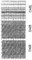
- Figure 2 illustrates pitches 1 to 3.
- Figure 2A indicates the focalized and aligned tracks of correlated and deconvolved registrations provided by the 100 measurements sequentially repeated for the same depth (1380 m/KB).
- Figure 2B illustrates the same 100 focalized tracks re-arranged with the ROP increasing drilling parameter.
- the horizontal scale is the sequential number of the re-arranged track.
- Figure 2C indicates the same re-arranged tracks, in the horizontal scale of the ROP drilling parameter.
- Figure 3 illustrates the results of steps 4 to 5.
- the ratio between signal energy and noise energy is calculated, selecting a span with respect to the aligned signal at 0.0 seconds for the signal, and a span with respect to the negative time data for the noise.
- the ratios between signal energy and noise energy for the progressive and partial sums are represented in figure 3A and 3B, respectively.
- step 6 This result is applied in step 6 to the original deconvolved, correlated tracks. This provides a clearer identification of the signal. See figure 4, where the seismic tracks of the level 1380 m/KB are represented with respect to the well distance (offset).
- Panel 4A indicates the result of the simple total sum
- figure 4B provides the result of the optimum sum.
- the reduction in the linear noise which extends from 0.2 seconds at low offsets to 1.0 seconds at high offsets, can be observed.
- figure 4C illustrates the range which allows a better identification of the noise obtained by summing the tracks for ROP values greater than 6 m/h.
Landscapes
- Physics & Mathematics (AREA)
- Life Sciences & Earth Sciences (AREA)
- Engineering & Computer Science (AREA)
- Remote Sensing (AREA)
- Geology (AREA)
- Environmental & Geological Engineering (AREA)
- Acoustics & Sound (AREA)
- General Life Sciences & Earth Sciences (AREA)
- General Physics & Mathematics (AREA)
- Geophysics (AREA)
- Geophysics And Detection Of Objects (AREA)
- Earth Drilling (AREA)
- Burglar Alarm Systems (AREA)
- Electrophonic Musical Instruments (AREA)
- Nuclear Medicine (AREA)
Abstract
- seismic and pilot signals (A);
- drilling parameters (B) relating to the signals (A);
the signals (A) are partially or totally summed up by weight, on the basis of one or more drilling parameters (B), or relative combinations of the above parameters, so as to obtain an improvement in the signal with respect to the noise, and a more distinct separation thereof.
Description
- seismic and pilot signals (A), preferably cross-correlated with each other and optionally deconvolved, thus obtaining seismic tracks in which the signal is disturbed by noise;
- drilling parameters (B) relating to the signals (A),
the signals (A), obtained with repeated measurements for the same depth range, preferably re-arranged and analyzed according to one or more drilling parameters (B) or their relative combinations, are partially or totally summed up by weight, on the basis of one or more drilling parameters (B), or relative combinations of the above parameters, thus obtaining an improvement in the signal with respect to noise, and a more distinct separation thereof.
| Parameter | Measurement unit |
| Date | |
| Hour | |
| Depth | meters |
| Vertical depth | meters |
| Bit depth | meters |
| Kelly position | meters |
| ROP (Rate of Penetration) | meters/hour |
| RPM | revs/minute |
| WOB (weight on bit) | Tons |
| Hookland | Tons |
| Torque | Kg/m |
| Pump pressure | Kg/cm3 |
| Mud in weight | gr/l |
| Mud out weight | gr/l |
| Flow in | l/m |
| Flow out | l/m |
| Pump tot | l/m |
| Bit distance | m |
| String length | m |
| String weight | Tons |
In figure 1 above:
Claims (7)
- A process for improving the Signal/Noise ratio in the preparation of vertical seismic profiles (VSP) which supply information on the gelogical formations of the subsoil subjected to drilling, using as signal the vibrations produced by the drilling bit adopted as seismic source; an extremely representative measurement of the above signal (pilot signal) and the measurements of the signals transmitted into the ground and reflected on the layers (seismic signals) being effected by means of a series of receivers which form the seismic line, the above process comprising the practically simultaneous acquisition of:characterized in that:seismic and pilot signals (A), cross-correlated with each other and optionally deconvolved, thus obtaining seismic tracks in which the signal is disturbed by noise;drilling parameters (B) relating to the signals (A),
the signals (A), obtained with repeated measurements for the same depth range, are partially or totally summed up by weight, on the basis of one or more drilling parameters (B), or relative combinations of the above parameters, thus obtaining an improvement in the signal with respect to noise, and a more distinct separation thereof. - The process according to claim 1, wherein the signals (A), before being partially or totally summed up, are re-arranged and analyzed according to one or more drilling parameters (B) or their relative combinations.
- The process according to claim 1, wherein the drilling parameters (B) are those which describe the dynamic drilling conditions, and relative combinations.
- The process according to claim 3, wherein the drilling parameters (B) are selected from torque, weight on bit, rate of penetration, rate of rotation, mud flow, and relative combinations.
- The process according to claim 1, which comprises the following steps:1) cross-correlation of the seismic signals and pilot signal (A), collected by repeated measurements for the same depth range, and possible deconvolution of these, thus obtaining seismic tracks (1);2) Identification of the arrival time of the direct wave from the bit in the tracks (1), the above identification being effected by selecting the tracks (1) of one or more channels of the seismic line, or using a representative channel synthesized from various channels of the seismic line (focalized signal), in order to obtain more representative tracks (2);3) Arrangement, and optional representation, of the tracks (2), relating to a given drilling range, in accordance with the values of one or more of the corresponding drilling parameters (B) or relative combinations, for a certain drilling range, thus obtaining arranged tracks (3);4) Channel by channel summing up with respect to appropriate subsets of the arranged tracks (3) thus obtaining summed-up tracks (4);5) Measurement of the Signal/Noise ratio for the summed-up tracks (4) and identification, among the subsets of point (4), of subset (s) forming the maximum value of the Signal/Noise ratio;6) Summing up, channel by channel and for the same depth range, of the tracks of point (2) or equivalently of point (1) according to the subsets identified in step (5), thus obtaining the optimum sum;7) Possible calculation of the noise range with the partial or total sum of the complementary range and identification of the associated operating conditions; possible subsequent subtraction of undesired noise, identified from the complementary range, from the signal selected with the optimum sum of (6), thus reducing the residual noise to the maximum.
- The process according to claim 5, wherein the tracks (2) are aligned according to the times identified in step 2, the aligned tracks thus obtained being used in the subsequent step (3).
- The process according to claim 5, wherein steps 1 to 6 or 1 to 7 are applied to various drilling levels.
Applications Claiming Priority (2)
| Application Number | Priority Date | Filing Date | Title |
|---|---|---|---|
| ITMI990814 IT1312187B1 (en) | 1999-04-20 | 1999-04-20 | PROCEDURE FOR IMPROVING THE SEISMIC CHISEL SIGNAL USING PERFORATION PARAMETERS |
| ITMI990814 | 1999-04-20 |
Publications (3)
| Publication Number | Publication Date |
|---|---|
| EP1046930A2 true EP1046930A2 (en) | 2000-10-25 |
| EP1046930A3 EP1046930A3 (en) | 2004-05-12 |
| EP1046930B1 EP1046930B1 (en) | 2007-08-01 |
Family
ID=11382770
Family Applications (1)
| Application Number | Title | Priority Date | Filing Date |
|---|---|---|---|
| EP00201332A Expired - Lifetime EP1046930B1 (en) | 1999-04-20 | 2000-04-13 | Process for improving the bit seismic signal using drilling parameters |
Country Status (9)
| Country | Link |
|---|---|
| EP (1) | EP1046930B1 (en) |
| BR (1) | BR0001655B1 (en) |
| DK (1) | DK1046930T3 (en) |
| DZ (1) | DZ3035A1 (en) |
| EG (1) | EG22067A (en) |
| IT (1) | IT1312187B1 (en) |
| PT (1) | PT1046930E (en) |
| RU (1) | RU2233001C2 (en) |
| TN (1) | TNSN00082A1 (en) |
Cited By (5)
| Publication number | Priority date | Publication date | Assignee | Title |
|---|---|---|---|---|
| WO2005090751A1 (en) * | 2004-03-17 | 2005-09-29 | Baker Hughes Incorporated | Seismic measurements while drilling |
| WO2009087207A3 (en) * | 2008-01-11 | 2010-07-08 | Istituto Nazionale Di Oceanografia E Di Geofisica Sperimentale - Ogs | Method for detecting and/or processing seismic signals |
| CN102788993A (en) * | 2012-08-13 | 2012-11-21 | 中国石油大学(华东) | 3D VSP (three-dimensional video signal processor) pre-stack imaging technology organically integrating optimization of migration aperture with avoidance of wavelet distortion |
| CN106547028A (en) * | 2015-09-21 | 2017-03-29 | 中国石油化工股份有限公司 | The method and apparatus of prediction shale reservoir TOC |
| WO2021137704A1 (en) * | 2019-12-30 | 2021-07-08 | Octio As | Virtual rvsp check shot from downhole seismic sources using seismic interferometry |
Families Citing this family (2)
| Publication number | Priority date | Publication date | Assignee | Title |
|---|---|---|---|---|
| RU2572668C1 (en) * | 2014-06-19 | 2016-01-20 | Российская Федерация, От Имени Которой Выступает Министерство Промышленности И Торговли Российской Федерации | Method of place determination of drill tool during drilling |
| CN106111346B (en) * | 2016-07-27 | 2018-09-11 | 湖北富邦科技股份有限公司 | A kind of phosphorite flotation collector and preparation method thereof for efficiently removing sesquichloride |
Family Cites Families (10)
| Publication number | Priority date | Publication date | Assignee | Title |
|---|---|---|---|---|
| US3520375A (en) * | 1969-03-19 | 1970-07-14 | Aquitaine Petrole | Method and apparatus for measuring mechanical characteristics of rocks while they are being drilled |
| US4561074A (en) * | 1982-12-29 | 1985-12-24 | Amoco Corporation | Computationally efficient weighting and vertical stacking methods and apparatus for improving signal-to-noise ratio of seismic data |
| US4926391A (en) * | 1986-12-30 | 1990-05-15 | Gas Research Institute, Inc. | Signal processing to enable utilization of a rig reference sensor with a drill bit seismic source |
| US5050130A (en) * | 1988-10-21 | 1991-09-17 | Gas Research Institute | Signal processing to enable utilization of a rig reference sensor with a drill bit seismic source |
| US4922362A (en) * | 1988-03-04 | 1990-05-01 | Schlumberger Technology Corporation | Methods for deconvolution of unknown source signatures from unknown waveform data |
| US4954998A (en) * | 1989-01-23 | 1990-09-04 | Western Atlas International, Inc. | Method for reducing noise in drill string signals |
| GB8916459D0 (en) * | 1989-07-19 | 1989-09-06 | Forex Neptune Serv Tech Sa | Method of monitoring the drilling of a borehole |
| US4965774A (en) * | 1989-07-26 | 1990-10-23 | Atlantic Richfield Company | Method and system for vertical seismic profiling by measuring drilling vibrations |
| FR2700018B1 (en) * | 1992-12-29 | 1995-02-24 | Inst Francais Du Petrole | Method and device for seismic prospecting using a drilling tool in action in a well. |
| IT1263156B (en) * | 1993-02-05 | 1996-08-01 | Agip Spa | PROCEDURE AND DETECTION DEVICE FOR SEISMIC SIGNALS TO OBTAIN VERTICAL SEISM PROFILES DURING PERFORATION OPERATIONS |
-
1999
- 1999-04-20 IT ITMI990814 patent/IT1312187B1/en active
-
2000
- 2000-04-13 DK DK00201332T patent/DK1046930T3/en active
- 2000-04-13 PT PT00201332T patent/PT1046930E/en unknown
- 2000-04-13 EP EP00201332A patent/EP1046930B1/en not_active Expired - Lifetime
- 2000-04-15 EG EG20000471A patent/EG22067A/en active
- 2000-04-18 TN TNTNSN00082A patent/TNSN00082A1/en unknown
- 2000-04-19 RU RU2000109485/03A patent/RU2233001C2/en not_active IP Right Cessation
- 2000-04-19 DZ DZ000071A patent/DZ3035A1/en active
- 2000-04-19 BR BR0001655A patent/BR0001655B1/en not_active IP Right Cessation
Cited By (8)
| Publication number | Priority date | Publication date | Assignee | Title |
|---|---|---|---|---|
| WO2005090751A1 (en) * | 2004-03-17 | 2005-09-29 | Baker Hughes Incorporated | Seismic measurements while drilling |
| GB2426338A (en) * | 2004-03-17 | 2006-11-22 | Baker Hughes Inc | Seismic measurements while drilling |
| GB2426338B (en) * | 2004-03-17 | 2008-09-10 | Baker Hughes Inc | Seismic measurements while drilling |
| WO2009087207A3 (en) * | 2008-01-11 | 2010-07-08 | Istituto Nazionale Di Oceanografia E Di Geofisica Sperimentale - Ogs | Method for detecting and/or processing seismic signals |
| CN102788993A (en) * | 2012-08-13 | 2012-11-21 | 中国石油大学(华东) | 3D VSP (three-dimensional video signal processor) pre-stack imaging technology organically integrating optimization of migration aperture with avoidance of wavelet distortion |
| CN102788993B (en) * | 2012-08-13 | 2017-02-08 | 中国石油大学(华东) | 3D VSP (three-dimensional video signal processor) pre-stack imaging method organically integrating optimization of migration aperture with avoidance of wavelet distortion |
| CN106547028A (en) * | 2015-09-21 | 2017-03-29 | 中国石油化工股份有限公司 | The method and apparatus of prediction shale reservoir TOC |
| WO2021137704A1 (en) * | 2019-12-30 | 2021-07-08 | Octio As | Virtual rvsp check shot from downhole seismic sources using seismic interferometry |
Also Published As
| Publication number | Publication date |
|---|---|
| TNSN00082A1 (en) | 2002-05-30 |
| ITMI990814A1 (en) | 2000-10-20 |
| EG22067A (en) | 2002-06-30 |
| DK1046930T3 (en) | 2007-11-26 |
| EP1046930B1 (en) | 2007-08-01 |
| BR0001655A (en) | 2001-10-09 |
| RU2233001C2 (en) | 2004-07-20 |
| EP1046930A3 (en) | 2004-05-12 |
| IT1312187B1 (en) | 2002-04-09 |
| PT1046930E (en) | 2007-11-15 |
| DZ3035A1 (en) | 2004-03-27 |
| BR0001655B1 (en) | 2013-02-19 |
Similar Documents
| Publication | Publication Date | Title |
|---|---|---|
| US6078868A (en) | Reference signal encoding for seismic while drilling measurement | |
| CA1177570A (en) | Apparatus and method for determining the position of a gas-saturated porous rock in the vicinity of a deep borehole in the earth | |
| Haldorsen et al. | Walk-away VSP using drill noise as a source | |
| Mohamed et al. | Site-specific shear wave velocity investigation for geotechnical engineering applications using seismic refraction and 2D multi-channel analysis of surface waves | |
| CA2333238C (en) | Method and apparatus for computing drill bit vibration power spectral density | |
| US20040162676A1 (en) | Method for borehole measurement of formation properties | |
| CA1261458A (en) | Sonic logging system | |
| US7508733B2 (en) | High-frequency processing of seismic vibrator data | |
| US4817059A (en) | Borehole logging methods for detection and imaging of formation structural features | |
| US4797859A (en) | Method for determining formation permeability by comparing measured tube waves with formation and borehole parameters | |
| Poletto et al. | Seismic-while-drilling by drill-bit source and large-aperture ocean-bottom array | |
| US5105391A (en) | Method for high-resolution seismic recording using detectors planted at shallow depths | |
| EP1046930B1 (en) | Process for improving the bit seismic signal using drilling parameters | |
| CN109188528A (en) | Elastic wave chromatographic imaging system and method between well | |
| Nakata et al. | Microseismicity observation and characterization at Cape Modern and Utah FORGE | |
| CN120010011A (en) | A method and system for predicting and identifying gypsum-salt rock in complex piedmont belts by combining well-seismic analysis | |
| Jarvis et al. | Near-surface VSP surveys using the seismic cone penetrometer | |
| RU2217778C2 (en) | Hydrocarbon prospecting method | |
| CN121091361B (en) | Virtual borehole method for inverting stratigraphic structure using a single six-component seismograph | |
| Murphy et al. | Seismic source characteristics of Soviet peaceful nuclear explosions | |
| Archuleta et al. | Engineering insights from data recorded on vertical arrays | |
| Yokota et al. | Seismic while drilling: basic experiments using a percussion drill as an energy source | |
| Pawar et al. | Measuring shear wave velocity using MASW method to reduce cost and time required in construction projects | |
| CA2610997C (en) | Method for coherence-filtering of acoustic array signal | |
| CN117250658B (en) | Methods for establishing seismic data sets for the study area |
Legal Events
| Date | Code | Title | Description |
|---|---|---|---|
| PUAI | Public reference made under article 153(3) epc to a published international application that has entered the european phase |
Free format text: ORIGINAL CODE: 0009012 |
|
| AK | Designated contracting states |
Kind code of ref document: A2 Designated state(s): AT BE CH CY DE DK ES FI FR GB GR IE IT LI LU MC NL PT SE |
|
| AX | Request for extension of the european patent |
Free format text: AL;LT;LV;MK;RO;SI |
|
| RIN1 | Information on inventor provided before grant (corrected) |
Inventor name: COMELLI, PAOLO Inventor name: ABRAMO, FERDINANDO Inventor name: POLETTO, FLAVIO Inventor name: MIRANDA, FRANCESCO |
|
| RIN1 | Information on inventor provided before grant (corrected) |
Inventor name: MIRANDA, FRANCESCO Inventor name: ABRAMO, FERDINANDO Inventor name: POLETTO, FLAVIO Inventor name: COMELLI, PAOLO |
|
| PUAL | Search report despatched |
Free format text: ORIGINAL CODE: 0009013 |
|
| RIC1 | Information provided on ipc code assigned before grant |
Ipc: 7G 01V 1/42 B Ipc: 7G 01V 1/36 A |
|
| AK | Designated contracting states |
Kind code of ref document: A3 Designated state(s): AT BE CH CY DE DK ES FI FR GB GR IE IT LI LU MC NL PT SE |
|
| AX | Request for extension of the european patent |
Extension state: AL LT LV MK RO SI |
|
| 17P | Request for examination filed |
Effective date: 20040622 |
|
| AKX | Designation fees paid |
Designated state(s): DK GB IE IT PT |
|
| REG | Reference to a national code |
Ref country code: DE Ref legal event code: 8566 |
|
| GRAP | Despatch of communication of intention to grant a patent |
Free format text: ORIGINAL CODE: EPIDOSNIGR1 |
|
| RAX | Requested extension states of the european patent have changed |
Extension state: RO Payment date: 20000413 Extension state: AL Payment date: 20000413 |
|
| GRAS | Grant fee paid |
Free format text: ORIGINAL CODE: EPIDOSNIGR3 |
|
| GRAA | (expected) grant |
Free format text: ORIGINAL CODE: 0009210 |
|
| AK | Designated contracting states |
Kind code of ref document: B1 Designated state(s): DK GB IE IT PT |
|
| AX | Request for extension of the european patent |
Extension state: AL RO |
|
| REG | Reference to a national code |
Ref country code: GB Ref legal event code: FG4D |
|
| REG | Reference to a national code |
Ref country code: IE Ref legal event code: FG4D |
|
| REG | Reference to a national code |
Ref country code: PT Ref legal event code: SC4A Free format text: AVAILABILITY OF NATIONAL TRANSLATION Effective date: 20071030 |
|
| REG | Reference to a national code |
Ref country code: DK Ref legal event code: T3 |
|
| PLBE | No opposition filed within time limit |
Free format text: ORIGINAL CODE: 0009261 |
|
| STAA | Information on the status of an ep patent application or granted ep patent |
Free format text: STATUS: NO OPPOSITION FILED WITHIN TIME LIMIT |
|
| 26N | No opposition filed |
Effective date: 20080506 |
|
| PGFP | Annual fee paid to national office [announced via postgrant information from national office to epo] |
Ref country code: IT Payment date: 20100427 Year of fee payment: 11 |
|
| PG25 | Lapsed in a contracting state [announced via postgrant information from national office to epo] |
Ref country code: IT Free format text: LAPSE BECAUSE OF NON-PAYMENT OF DUE FEES Effective date: 20110413 |
|
| PGFP | Annual fee paid to national office [announced via postgrant information from national office to epo] |
Ref country code: GB Payment date: 20140409 Year of fee payment: 15 Ref country code: IE Payment date: 20140410 Year of fee payment: 15 |
|
| PGFP | Annual fee paid to national office [announced via postgrant information from national office to epo] |
Ref country code: PT Payment date: 20140401 Year of fee payment: 15 |
|
| PGFP | Annual fee paid to national office [announced via postgrant information from national office to epo] |
Ref country code: DK Payment date: 20140410 Year of fee payment: 15 |
|
| REG | Reference to a national code |
Ref country code: PT Ref legal event code: MM4A Free format text: LAPSE DUE TO NON-PAYMENT OF FEES Effective date: 20151013 |
|
| REG | Reference to a national code |
Ref country code: DK Ref legal event code: EBP Effective date: 20150430 |
|
| GBPC | Gb: european patent ceased through non-payment of renewal fee |
Effective date: 20150413 |
|
| REG | Reference to a national code |
Ref country code: IE Ref legal event code: MM4A |
|
| PG25 | Lapsed in a contracting state [announced via postgrant information from national office to epo] |
Ref country code: GB Free format text: LAPSE BECAUSE OF NON-PAYMENT OF DUE FEES Effective date: 20150413 |
|
| PG25 | Lapsed in a contracting state [announced via postgrant information from national office to epo] |
Ref country code: PT Free format text: LAPSE BECAUSE OF NON-PAYMENT OF DUE FEES Effective date: 20151013 |
|
| PG25 | Lapsed in a contracting state [announced via postgrant information from national office to epo] |
Ref country code: DK Free format text: LAPSE BECAUSE OF NON-PAYMENT OF DUE FEES Effective date: 20150430 Ref country code: IE Free format text: LAPSE BECAUSE OF NON-PAYMENT OF DUE FEES Effective date: 20150413 |