EP1046928A2 - Method and apparatus for flow imaging using coded excitation - Google Patents
Method and apparatus for flow imaging using coded excitation Download PDFInfo
- Publication number
- EP1046928A2 EP1046928A2 EP00303308A EP00303308A EP1046928A2 EP 1046928 A2 EP1046928 A2 EP 1046928A2 EP 00303308 A EP00303308 A EP 00303308A EP 00303308 A EP00303308 A EP 00303308A EP 1046928 A2 EP1046928 A2 EP 1046928A2
- Authority
- EP
- European Patent Office
- Prior art keywords
- transmit
- signal
- flow
- wave energy
- image
- Prior art date
- Legal status (The legal status is an assumption and is not a legal conclusion. Google has not performed a legal analysis and makes no representation as to the accuracy of the status listed.)
- Granted
Links
Images


Classifications
-
- G—PHYSICS
- G01—MEASURING; TESTING
- G01S—RADIO DIRECTION-FINDING; RADIO NAVIGATION; DETERMINING DISTANCE OR VELOCITY BY USE OF RADIO WAVES; LOCATING OR PRESENCE-DETECTING BY USE OF THE REFLECTION OR RERADIATION OF RADIO WAVES; ANALOGOUS ARRANGEMENTS USING OTHER WAVES
- G01S7/00—Details of systems according to groups G01S13/00, G01S15/00, G01S17/00
- G01S7/52—Details of systems according to groups G01S13/00, G01S15/00, G01S17/00 of systems according to group G01S15/00
- G01S7/52017—Details of systems according to groups G01S13/00, G01S15/00, G01S17/00 of systems according to group G01S15/00 particularly adapted to short-range imaging
- G01S7/52046—Techniques for image enhancement involving transmitter or receiver
-
- G—PHYSICS
- G01—MEASURING; TESTING
- G01S—RADIO DIRECTION-FINDING; RADIO NAVIGATION; DETERMINING DISTANCE OR VELOCITY BY USE OF RADIO WAVES; LOCATING OR PRESENCE-DETECTING BY USE OF THE REFLECTION OR RERADIATION OF RADIO WAVES; ANALOGOUS ARRANGEMENTS USING OTHER WAVES
- G01S15/00—Systems using the reflection or reradiation of acoustic waves, e.g. sonar systems
- G01S15/88—Sonar systems specially adapted for specific applications
- G01S15/89—Sonar systems specially adapted for specific applications for mapping or imaging
- G01S15/8906—Short-range imaging systems; Acoustic microscope systems using pulse-echo techniques
- G01S15/895—Short-range imaging systems; Acoustic microscope systems using pulse-echo techniques characterised by the transmitted frequency spectrum
- G01S15/8954—Short-range imaging systems; Acoustic microscope systems using pulse-echo techniques characterised by the transmitted frequency spectrum using a broad-band spectrum
-
- G—PHYSICS
- G01—MEASURING; TESTING
- G01S—RADIO DIRECTION-FINDING; RADIO NAVIGATION; DETERMINING DISTANCE OR VELOCITY BY USE OF RADIO WAVES; LOCATING OR PRESENCE-DETECTING BY USE OF THE REFLECTION OR RERADIATION OF RADIO WAVES; ANALOGOUS ARRANGEMENTS USING OTHER WAVES
- G01S15/00—Systems using the reflection or reradiation of acoustic waves, e.g. sonar systems
- G01S15/88—Sonar systems specially adapted for specific applications
- G01S15/89—Sonar systems specially adapted for specific applications for mapping or imaging
- G01S15/8906—Short-range imaging systems; Acoustic microscope systems using pulse-echo techniques
- G01S15/8959—Short-range imaging systems; Acoustic microscope systems using pulse-echo techniques using coded signals for correlation purposes
-
- G—PHYSICS
- G01—MEASURING; TESTING
- G01S—RADIO DIRECTION-FINDING; RADIO NAVIGATION; DETERMINING DISTANCE OR VELOCITY BY USE OF RADIO WAVES; LOCATING OR PRESENCE-DETECTING BY USE OF THE REFLECTION OR RERADIATION OF RADIO WAVES; ANALOGOUS ARRANGEMENTS USING OTHER WAVES
- G01S15/00—Systems using the reflection or reradiation of acoustic waves, e.g. sonar systems
- G01S15/88—Sonar systems specially adapted for specific applications
- G01S15/89—Sonar systems specially adapted for specific applications for mapping or imaging
- G01S15/8906—Short-range imaging systems; Acoustic microscope systems using pulse-echo techniques
- G01S15/8959—Short-range imaging systems; Acoustic microscope systems using pulse-echo techniques using coded signals for correlation purposes
- G01S15/8961—Short-range imaging systems; Acoustic microscope systems using pulse-echo techniques using coded signals for correlation purposes using pulse compression
-
- G—PHYSICS
- G01—MEASURING; TESTING
- G01S—RADIO DIRECTION-FINDING; RADIO NAVIGATION; DETERMINING DISTANCE OR VELOCITY BY USE OF RADIO WAVES; LOCATING OR PRESENCE-DETECTING BY USE OF THE REFLECTION OR RERADIATION OF RADIO WAVES; ANALOGOUS ARRANGEMENTS USING OTHER WAVES
- G01S15/00—Systems using the reflection or reradiation of acoustic waves, e.g. sonar systems
- G01S15/88—Sonar systems specially adapted for specific applications
- G01S15/89—Sonar systems specially adapted for specific applications for mapping or imaging
- G01S15/8906—Short-range imaging systems; Acoustic microscope systems using pulse-echo techniques
- G01S15/8979—Combined Doppler and pulse-echo imaging systems
- G01S15/8988—Colour Doppler imaging
-
- G—PHYSICS
- G01—MEASURING; TESTING
- G01S—RADIO DIRECTION-FINDING; RADIO NAVIGATION; DETERMINING DISTANCE OR VELOCITY BY USE OF RADIO WAVES; LOCATING OR PRESENCE-DETECTING BY USE OF THE REFLECTION OR RERADIATION OF RADIO WAVES; ANALOGOUS ARRANGEMENTS USING OTHER WAVES
- G01S15/00—Systems using the reflection or reradiation of acoustic waves, e.g. sonar systems
- G01S15/88—Sonar systems specially adapted for specific applications
- G01S15/89—Sonar systems specially adapted for specific applications for mapping or imaging
- G01S15/8906—Short-range imaging systems; Acoustic microscope systems using pulse-echo techniques
- G01S15/8993—Three dimensional imaging systems
-
- G—PHYSICS
- G01—MEASURING; TESTING
- G01S—RADIO DIRECTION-FINDING; RADIO NAVIGATION; DETERMINING DISTANCE OR VELOCITY BY USE OF RADIO WAVES; LOCATING OR PRESENCE-DETECTING BY USE OF THE REFLECTION OR RERADIATION OF RADIO WAVES; ANALOGOUS ARRANGEMENTS USING OTHER WAVES
- G01S7/00—Details of systems according to groups G01S13/00, G01S15/00, G01S17/00
- G01S7/52—Details of systems according to groups G01S13/00, G01S15/00, G01S17/00 of systems according to group G01S15/00
- G01S7/52017—Details of systems according to groups G01S13/00, G01S15/00, G01S17/00 of systems according to group G01S15/00 particularly adapted to short-range imaging
- G01S7/52023—Details of receivers
-
- G—PHYSICS
- G01—MEASURING; TESTING
- G01S—RADIO DIRECTION-FINDING; RADIO NAVIGATION; DETERMINING DISTANCE OR VELOCITY BY USE OF RADIO WAVES; LOCATING OR PRESENCE-DETECTING BY USE OF THE REFLECTION OR RERADIATION OF RADIO WAVES; ANALOGOUS ARRANGEMENTS USING OTHER WAVES
- G01S7/00—Details of systems according to groups G01S13/00, G01S15/00, G01S17/00
- G01S7/52—Details of systems according to groups G01S13/00, G01S15/00, G01S17/00 of systems according to group G01S15/00
- G01S7/52017—Details of systems according to groups G01S13/00, G01S15/00, G01S17/00 of systems according to group G01S15/00 particularly adapted to short-range imaging
- G01S7/52023—Details of receivers
- G01S7/52036—Details of receivers using analysis of echo signal for target characterisation
- G01S7/52038—Details of receivers using analysis of echo signal for target characterisation involving non-linear properties of the propagation medium or of the reflective target
- G01S7/52039—Details of receivers using analysis of echo signal for target characterisation involving non-linear properties of the propagation medium or of the reflective target exploiting the non-linear response of a contrast enhancer, e.g. a contrast agent
-
- G—PHYSICS
- G01—MEASURING; TESTING
- G01S—RADIO DIRECTION-FINDING; RADIO NAVIGATION; DETERMINING DISTANCE OR VELOCITY BY USE OF RADIO WAVES; LOCATING OR PRESENCE-DETECTING BY USE OF THE REFLECTION OR RERADIATION OF RADIO WAVES; ANALOGOUS ARRANGEMENTS USING OTHER WAVES
- G01S7/00—Details of systems according to groups G01S13/00, G01S15/00, G01S17/00
- G01S7/52—Details of systems according to groups G01S13/00, G01S15/00, G01S17/00 of systems according to group G01S15/00
- G01S7/52017—Details of systems according to groups G01S13/00, G01S15/00, G01S17/00 of systems according to group G01S15/00 particularly adapted to short-range imaging
- G01S7/52053—Display arrangements
- G01S7/52057—Cathode ray tube displays
- G01S7/5206—Two-dimensional coordinated display of distance and direction; B-scan display
-
- G—PHYSICS
- G01—MEASURING; TESTING
- G01S—RADIO DIRECTION-FINDING; RADIO NAVIGATION; DETERMINING DISTANCE OR VELOCITY BY USE OF RADIO WAVES; LOCATING OR PRESENCE-DETECTING BY USE OF THE REFLECTION OR RERADIATION OF RADIO WAVES; ANALOGOUS ARRANGEMENTS USING OTHER WAVES
- G01S15/00—Systems using the reflection or reradiation of acoustic waves, e.g. sonar systems
- G01S15/88—Sonar systems specially adapted for specific applications
- G01S15/89—Sonar systems specially adapted for specific applications for mapping or imaging
- G01S15/8906—Short-range imaging systems; Acoustic microscope systems using pulse-echo techniques
- G01S15/8909—Short-range imaging systems; Acoustic microscope systems using pulse-echo techniques using a static transducer configuration
- G01S15/8915—Short-range imaging systems; Acoustic microscope systems using pulse-echo techniques using a static transducer configuration using a transducer array
- G01S15/8918—Short-range imaging systems; Acoustic microscope systems using pulse-echo techniques using a static transducer configuration using a transducer array the array being linear
-
- G—PHYSICS
- G01—MEASURING; TESTING
- G01S—RADIO DIRECTION-FINDING; RADIO NAVIGATION; DETERMINING DISTANCE OR VELOCITY BY USE OF RADIO WAVES; LOCATING OR PRESENCE-DETECTING BY USE OF THE REFLECTION OR RERADIATION OF RADIO WAVES; ANALOGOUS ARRANGEMENTS USING OTHER WAVES
- G01S15/00—Systems using the reflection or reradiation of acoustic waves, e.g. sonar systems
- G01S15/88—Sonar systems specially adapted for specific applications
- G01S15/89—Sonar systems specially adapted for specific applications for mapping or imaging
- G01S15/8906—Short-range imaging systems; Acoustic microscope systems using pulse-echo techniques
- G01S15/8979—Combined Doppler and pulse-echo imaging systems
-
- G—PHYSICS
- G01—MEASURING; TESTING
- G01S—RADIO DIRECTION-FINDING; RADIO NAVIGATION; DETERMINING DISTANCE OR VELOCITY BY USE OF RADIO WAVES; LOCATING OR PRESENCE-DETECTING BY USE OF THE REFLECTION OR RERADIATION OF RADIO WAVES; ANALOGOUS ARRANGEMENTS USING OTHER WAVES
- G01S15/00—Systems using the reflection or reradiation of acoustic waves, e.g. sonar systems
- G01S15/88—Sonar systems specially adapted for specific applications
- G01S15/89—Sonar systems specially adapted for specific applications for mapping or imaging
- G01S15/8906—Short-range imaging systems; Acoustic microscope systems using pulse-echo techniques
- G01S15/8979—Combined Doppler and pulse-echo imaging systems
- G01S15/8981—Discriminating between fixed and moving objects or between objects moving at different speeds, e.g. wall clutter filter
-
- G—PHYSICS
- G01—MEASURING; TESTING
- G01S—RADIO DIRECTION-FINDING; RADIO NAVIGATION; DETERMINING DISTANCE OR VELOCITY BY USE OF RADIO WAVES; LOCATING OR PRESENCE-DETECTING BY USE OF THE REFLECTION OR RERADIATION OF RADIO WAVES; ANALOGOUS ARRANGEMENTS USING OTHER WAVES
- G01S7/00—Details of systems according to groups G01S13/00, G01S15/00, G01S17/00
- G01S7/52—Details of systems according to groups G01S13/00, G01S15/00, G01S17/00 of systems according to group G01S15/00
- G01S7/52017—Details of systems according to groups G01S13/00, G01S15/00, G01S17/00 of systems according to group G01S15/00 particularly adapted to short-range imaging
- G01S7/52023—Details of receivers
- G01S7/52036—Details of receivers using analysis of echo signal for target characterisation
- G01S7/52038—Details of receivers using analysis of echo signal for target characterisation involving non-linear properties of the propagation medium or of the reflective target
-
- Y—GENERAL TAGGING OF NEW TECHNOLOGICAL DEVELOPMENTS; GENERAL TAGGING OF CROSS-SECTIONAL TECHNOLOGIES SPANNING OVER SEVERAL SECTIONS OF THE IPC; TECHNICAL SUBJECTS COVERED BY FORMER USPC CROSS-REFERENCE ART COLLECTIONS [XRACs] AND DIGESTS
- Y10—TECHNICAL SUBJECTS COVERED BY FORMER USPC
- Y10S—TECHNICAL SUBJECTS COVERED BY FORMER USPC CROSS-REFERENCE ART COLLECTIONS [XRACs] AND DIGESTS
- Y10S128/00—Surgery
- Y10S128/916—Ultrasound 3-D imaging
Definitions
- This invention generally relates to ultrasound imaging systems.
- the invention relates to methods and apparatus for imaging blood flow and contrast agents.
- Conventional ultrasound scanners create two-dimensional B-mode images of tissue in which the brightness of a pixel is based on the intensity of the echo return. In a so-called "color flow” mode, the flow of blood or movement of tissue can be imaged.
- Conventional ultrasound flow imaging methods use either the Doppler principle or a time-domain cross-correlation method to estimate the average flow velocity, which is then displayed in color overlaid on a B-mode image.
- the frequency shift of backscattered ultrasound waves may be used to measure the velocity of the backscatterers from tissue or blood.
- the change or shift in backscattered frequency increases when blood flows toward the transducer and decreases when blood flows away from the transducer.
- the Doppler shift may be processed to estimate the average flow velocity, which is displayed using different colors to represent speed and direction of flow.
- the color flow velocity mode displays hundreds of adjacent sample volumes simultaneously, all color-coded to represent each sample volume's velocity.
- Conventional ultrasound flow imaging displays either the average Doppler power ("power Doppler imaging”) or the average flow velocity (“color flow velocity imaging”) as a color overlay on a B-mode image.
- the transmitted pulses are typically more narrowband than B-mode pulses in order to gain Doppler sensitivity.
- a high-pass wall filter Operating on a packet of as many as 16 transmits, a high-pass wall filter first rejects echoes from slower-moving tissue or vessel walls to reduce the signal dynamic range.
- the number of wall filter output samples per packet is given by ( N - W +1 ), where N is packet size and W is wall filter length.
- the instantaneous Doppler power is computed as The magnitude squared of each wall filter quadrature output signal and The average of all quadrature output signals yields the average Doppler power.
- the average velocity is computed from the wall filter quadrature output signals based on the Doppler principle (phase change) or time delay between firings.
- the Kasai autocorrelation algorithm or a time-domain cross-correlation algorithm can be used to estimate the average flow velocity.
- ultrasound images are formed from a combination of fundamental and harmonic signal components, the latter of which are generated in a nonlinear medium such as tissue or a blood stream containing contrast agents.
- ultrasound images may be improved by suppressing the fundamental and emphasizing the harmonic signal components.
- Contrast agents have been developed for medical ultrasound to aid in diagnosis of traditionally difficult-to-image vascular anatomy.
- the agents which are typically microbubbles whose diameter is in the range of 1-10 micrometers, are injected into the blood stream. Since the backscatter signal of the microbubbles is much larger than that of blood cells, the microbubbles are used as markers to allow imaging of blood flow.
- One method to further isolate echoes from these agents is to use the (sub)harmonic components of the contrast echo, which is much larger than the harmonic components of the surrounding tissue without contrast agent [See, e.g., Newhouse et al ., "Second Harmonic Doppler Ultrasound Blood Perfusion Measurement” Proc. 1992 IEEE Ultrason. Symp., pp. 1175-1177; and Burns, et al ., "Harmonic Power Mode Doppler Using Microbubble Contrast Agents: An Improved Method for Small Vessel Flow Imaging," Proc. 1994 IEEE Ultrason. Symp., pp.
- Contrast imaging of (sub)harmonic signals has largely been performed by transmitting a narrow-band signal at frequency and receiving at a band centered at frequency 2 (second harmonic) or at frequency /2 (subharmonic) followed by conventional color flow processing.
- This approach has all the limitations of a conventional color flow system, namely, low resolution, low frame rate and flow sensitivity only in the axial direction.
- SNR signal-to-noise ratio
- Additional SNR can be used to obtain increased penetration at a given imaging frequency or to improve resolution by facilitating ultrasonic imaging at a higher frequency.
- Coded excitation is a well-known radar technique used to increase signal-to-noise ratio in situations where the peak power of a transmitted signal cannot be increased but the average power can. This is often the situation in medical ultrasound imaging, where system design limitations dictate the peak amplitude of the signal driving the transducer. In this situation, longer signals, such as chirps, can be used to deliver higher average power values, and temporal resolution is restored by correlating the return signal with a matched filter.
- Chirps are expensive to implement on a phased array ultrasound system due to the complexity of the electronics, so binary codes, or codes that can be easily represented digitally as a series of digits of +1, -1 or 0, are much more practical. Binary codes are also preferred because they contain the most energy for a given peak amplitude and pulse duration.
- a method and apparatus for imaging blood flow with high resolution, high frame rate, high SNR/dynamic range and flow sensitivity in all directions achieves clinical benefits including clear visualization of complex hemodynamics, residual lumen in stenosis and thrombus motion.
- High resolution is achieved by using broadband pulses, while high frame rate is achieved by using small packet sizes.
- High SNR/dynamic range is maintained by using coded excitation.
- Flow sensitivity in the range direction is highest and arises from pulse-to-pulse RF decorrelation, while flow sensitivity in the cross-range direction is due to pulse-to-pulse amplitude decorrelation as a group of reflectors (e.g. blood or contrast agents) flows across the beam profile.
- a small packet of coded broadband pulses is transmitted with a given pulse repetition interval to a transmit focal position.
- the backscattered signals from this sequence of firings are filtered in slow time to remove echoes from stationary or slower-moving reflectors along the transmit path.
- the packet size is small (under six firings) to achieve high frame rate, though with the undesirable side effect of reduced SNR.
- SNR is recovered by using coded excitation.
- the slow-time filtering is preferably performed by a high-pass FIR (finite impulse response) or IIR (infinite impulse response) wall filter.
- the wall filter increases the flow signal-to-clutter ratio, which may be further increased by administering a contrast agent to the patient prior to imaging.
- a flow image is formed by scanning the transmit focal position across the region of interest
- the scan direction is opposite that of the flow direction for maximum apparent resolution and flow sensitivity.
- Frame rate may be increased by simultaneously processing more than one receive vector from a single transmit vector with parallel receive hardware.
- the packet size, pulse repetition interval (PRI) and region of interest (ROI) may be controlled by the user.
- a coded sequence of broadband pulses (centered at a fundamental frequency) is transmitted multiple times to a particular transmit focal position, each coded sequence constituting one firing.
- the receive pulses acquired for each firing are compressed and bandpass filtered, e.g., to isolate a compressed pulse centered at the fundamental frequency.
- the compressed and isolated signals are then high pass filtered across firings using a wall filter.
- the wall-filtered signals are used to image blood flow without injecting contrast agents into the blood.
- contrast agents such as gas-filled microbubbles are injected into the blood to serve as markers for imaging blood flow.
- a coded sequence of broadband pulses is transmitted multiple times to a particular transmit focal position.
- Fundamental and (sub)harmonic signals are generated from interaction between the transmitted ultrasound pulses and the propagation medium, especially the injected contrast agents.
- the receive signals are decoded and bandpass filtered to isolate the fundamental signals.
- the isolated fundamental signals are then high-pass filtered across firings using a wall filter.
- fundamental signals reflected from non-stationary tissue or flow regions along the transmit path can be extracted.
- the resulting flow signals can be superimposed on, or summed with, a conventional B-mode imaging data vector and displayed. Received energy at the fundamental frequency which would have contributed to undesirable stationary tissue signal is suppressed by the wall filter.
- the flow image may be combined with a stationary tissue (i.e., B-mode) image acquired by detecting either The fundamental or (sub)harmonic signal components, either by summation or as an overlay in order to provide anatomical landmarks.
- B-mode stationary tissue
- An advantage of the overlay is that it may be done in color so that the flow regions stand out clearly.
- this method requires more complex display hardware and additional firings (to acquire imaging data representing stationary tissue) beyond those used for flow imaging.
- the flash artifacts are severe. Injection of the background B-mode image by summation (either coherent or incoherent) results in more benign flash artifacts.
- a B-mode image may be added with (for a harmonic B-mode image) or without (for a fundamental B-mode image) additional firings.
- the firings are interleaved and the flow signals may be thresholded separately from the B-mode signals prior to display.
- the method of the invention differs from both conventional power Doppler and color flow velocity imaging in several respects.
- the inventive method does not extract the Doppler signal and so is able to use broadband pulses.
- the inventive method does not require either baseband data (although it can use baseband data) or velocity estimation.
- the summation method of providing a B-mode background is simpler (less display hardware is required), more efficient (the feedthrough method does not require additional transmits to acquire a fundamental B-mode image), and more effective (more benign flash artifacts) than the conventional overlay method.
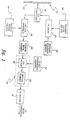
- FIG. 1 A conventional ultrasonic imaging system is depicted in FIG. 1.
- the system comprises a transducer array 10 having a plurality of separately driven transducer elements 12, each of which produces a burst of ultrasonic energy when energized by a pulsed waveform produced by a transmitter 14.
- the ultrasonic energy reflected back to transducer array 10 from the object under study is converted to an analog electrical signal by each receiving transducer element 12 and applied separately to a receiver 16 through a set of transmit/receive (T/R) switches 18.
- Transmitter 14 and receiver 16 are operated under control of a host computer or master controller 20 responsive to commands supplied by a human operator via an operator interface (not shown).
- a complete scan is performed by acquiring a series of echoes in which transmitter 14 is gated ON momentarily to energize each transducer element 12, and the subsequent echo signals produced by each transducer element 12 are applied to receiver 16.
- Receiver 16 converts the analog echo signals to digital signals and combines the respective digital signals derived from each transducer element to produce a single beamsummed signal which is used to produce a line in an image displayed by a display subsystem 22.
- transmitter 14 drives transducer array 10 such that the ultrasonic energy is transmitted as a directed focused beam.
- respective time delays are imparted to a multiplicity of pulsers 24 by a transmit beamformer 26.
- Host computer 20 determines the conditions under which the acoustic pulses will be transmitted. With this information, transmit beamformer 26 determines the timing and amplitudes of each of the transmit pulses to be generated by pulsers 24. The amplitudes of each transmit pulse are generated by an apodization generation circuit 36, such as a high-voltage controller that sets the power supply voltage to each pulser.
- Pulsers 24 in turn send the transmit pulses to each of elements 12 of transducer array 10 via T/R switches 18, which protect time-gain compensation (TGC) amplifiers 28 from the high voltages which may exist at the transducer array.
- TGC time-gain compensation
- the apodization weightings are selected to achieve optimal compromise between transmit power and sidelobe level. Weightings are generated by apodization generation circuit 36, which may comprise a set of digital-to-analog converters that take the weighting data from transmit beamformer 26 and apply it to pulsers 24.
- apodization weightings and the transmit focus time delays may be set by The host computer based on system programming and operator inputs.
- Each burst of ultrasonic energy is reflected from objects located at successive ranges along each transmit beam.
- the resulting echo signals are sensed separately by each transducer element 12 and a sample of the echo signal magnitude at a particular point in time represents the amount of reflection occurring at a specific range. Due to the differences in the propagation paths between a reflecting point and each transducer element 12, the echo signals are not detected simultaneously and their amplitudes are not equal.
- Receiver 16 amplifies the separate echo signals via a respective TGC amplifier 28 in each receive channel. TGC is carried out by increasing or decreasing gain as a function of depth. The amount of amplification provided by the TGC amplifiers is controlled by a TGC circuit (not shown), which is set by the host computer and manual operation of potentiometers. The amplified echo signals are then fed to a receive beamformer 30.
- receive beamformer 30 tracks the direction of the transmitted beam.
- Receive beamformer 30 imparts the proper time delays and receive apodization weightings to each amplified echo signal and sums these signals to provide an echo signal which accurately represents the total ultrasonic energy reflected from a point located at a particular range in a particular transmit direction.
- the receive focus time delays are computed in real-time using specialized hardware, or are read from a lookup table.
- the receive channels also have circuitry for filtering the received pulses.
- the receive apodization weightings and receive focus time delays may be set by the host computer based on system programming and operator inputs.
- the time-delayed receive signals are then summed and provided to a signal processor or detector 32 which converts the summed receive signals to display data.
- the display data are the envelope of the signal with some additional processing, such as edge enhancement and logarithmic compression.
- the envelope can be detected using a low-pass filter for baseband data, the envelope can be detected using an envelope detector which produces a signal representing ( I 2 + Q 2 ) 1 ⁇ 2 , where I is the in-phase signal component and Q is the quadrature signal component of the baseband data.
- Scan converter 34 receives the display data from detector 32 and converts the data into the desired image for display.
- scan converter 34 converts the acoustic image data from polar coordinate ( R X ⁇ ) sector format or Cartesian coordinate linear array to appropriately scaled Cartesian coordinate display pixel data at the video rate.
- the scan-converted acoustic data are then provided for display by display subsystem 22, which images the time-varying amplitude of the envelope of the signal as a gray scale. A respective scan line is displayed for each transmit beam.
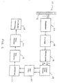
- FIG. 2 shows an ultrasound flow imaging system in accordance with one preferred embodiment of the invention.
- Each transducer element in the transmit aperture is. pulsed N times (where N is preferably 6 or less) using the same coded waveform by supplying the same transmit sequence from a memory 38 into each pulser N times.
- Pulsers 24 drive elements 12 of transducer array 10 such that the ultrasonic energy produced is directed or steered in a beam for each transmit firing.
- transmit focus time delays 36 are imparted to the respective pulsed waveforms produced by the pulsers in response to the transmit sequence from memory 38.
- the N pulses are transmitted to the transmit focal position with a specified pulse repetition interval (PRI).
- the transmit sequences are supplied by the host computer based on system programming and operator inputs.
- the basic concept of the single-transmit coded excitation comprises modulating a specially designed code sequence based on a transmit burst (base sequence) of length P.
- a coded pulse sequence of n bursts is often referred to as an n -chip code.
- the coded pulse sequence which has a length n x P , enables a larger acoustic dosage or a shorter base sequence to be used to interrogate the flowing blood.
- the output signal of the decoding (i.e., compression) filter is a compressed signal pulse of length equal, or close to, the original transmit burst length P , but whose amplitude is that produced by the n -times-longer coded pulse sequence.
- This coding technique has no adverse effects on frame rate and has much less chance of improper decoding due to high velocities or adaptive rotation.
- a single coded waveform is transmitted and the received waveform is convolved with the decoding filter impulse response to compress the waveform energy into a small time interval.
- the decoding filter may be a matched filter (wherein the filter coefficients are the same as the transmit code) or a mismatched filter.
- the mismatched filter is designed to minimize the sum of squares error between the filter output signal (with the code sequence as input signal) and a Kronecker delta function.
- Preferred single-transmit codes include Barker codes and non-Barker codes such as the length-8 code [1,1,1,-1,1,-1,-1,1].
- the echo signals from transducer elements 12 are fed to respective receive channels 40 of the receive beamformer.
- the receive beamformer tracks the direction of the transmitted beam.
- the receive beamformer imparts the proper receive focus time delays 42 to the received echo signal and sums the echo signals to provide a composite echo signal which accurately represents the total ultrasonic energy reflected from a particular position along a transmit beam.
- the time-delayed receive signals are summed in a receive summer 44 for each of the N transmit firings focused at a particular transmit focal position.
- the summed receive signals for successive transmit firings are supplied to a filter 46 which performs the functions of decoding, bandpass filtering and wall filtering. This is accomplished by proper selection of the filter coefficients by the host computer based on system programming and operator inputs. Alter 46 filters across the N transmit firings and supplies a filtered signal to detector 32 which forms the envelope of the firing-to-firing filtered signal.
- a scan line is displayed by display subsystem 22 (FIG. 1). This procedure is repeated so that a respective scan line is displayed for each transmit focal position (in the situation of one transmit focal position for each beam angle) or for each vector (in the situation of multiple transmit focal positions for each beam angle).
- filter 46 comprises an FIR filter 48 having an input coupled to the output of receive summer 44; and a vector summer 50 having an input coupled to FIR filter 48 and an output coupled to detector 32.
- the FIR filter has M filter taps for receipt of a respective set of M filter coefficients for each transmit firing.
- the scalar weightings a 1 , a 2 , ..., a N form a "wall" filter in slow time which selectively passes signals from reflectors moving at a velocity greater than a predetermined threshold, i.e., The slow-time filter coefficients are chosen to reject low frequencies which correspond to motion at lower speeds.
- the successive FIR filter output signals for the N transmit firings are coherently accumulated in vector summer 50. This is equivalent to a wall filter with a single output signal sample.
- the output signal of the vector summer then undergoes envelope detection, post-processing, scan conversion and display in a known manner.
- the filter coefficients a n c 1 , a n c 2 , ..., a n c M are provided to filter 48 for each transmit firing by the host computer from a filter coefficient memory 52.
- the set of filter coefficients a 1 c 1 , a 1 c 2 , ..., a 1 c M is supplied to FIR filter 48;
- the set of filter coefficients a 2 c 1 , a 2 c 2 , ..., a 2 c M is supplied to the FIR filter; and so forth.
- the filter coefficients are programmable, depending upon the diagnostic application.
- Different sets of filter coefficients can be stored in lookup tables in the memory of the host computer and the desired set of coefficients can be selectable by the system operator.
- the number of transmit firings N 2
- pairs of sets of filter coefficients are stored in memory, one s e t of filter coefficients of a selected pair being transferred to the FIR filter before the first transmit firing and the other set of filter coefficients of the selected pair being transferred to the FIR filter after the first transmit firing and before the second transmit firing.
- two or three sets of filter coefficients are stored in memory for use in filtering the receive signals resulting from the first through third firings.
- a similar procedure is followed for applications where the number of transmit firings N > 3.
- the time interval between each of the N transmits per focal position is user controllable to determine the "slow-time" filter cutoff frequency. A longer interval between each of the N transmits to a particular focal position results in a lower cutoff frequency with higher sensitivity to low velocity flow.
- the flow image may be displayed by itself for maximum flow contrast, or may be summed with a B-mode background image.
- Superimposition of the flow image on a conventional B-mode image allows the diagnostician to observe the flow of blood relative to known anatomical landmarks during medical diagnosis.
- the flash artifact seen in this summation of flow and B-mode images is more benign than that found in conventional color-flow imaging.
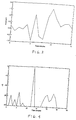
- a B-mode image derived from the fundamental frequency band is summed with the flow image. This is achieved by perturbing one of the "slow-time" filter weightings so that a fundamental B-mode signal component is passed or fed through the wall filter. For example, the weighting a 1 for the first transmit firing (or for any other transmit firing) can be perturbed by an amount ⁇ , as shown in FIG. 5.
- the B-mode feedthrough allows the flow image to be superimposed on a conventional B-mode image for display. Alternatively, the flow image may be superimposed in color on a conventional B-mode image for display. This feedthrough technique is one way of obtaining the B-mode background image without additional firings.
- the background B-mode image may also be a (sub)harmonic image, which helps to clear up certain image artifacts such as reverberations and out-of-plane acoustic "noise" which may obscure flow imaging. This can be achieved in any one of several ways.
- an additional uncoded pulse is transmitted at (usually the transducer lower frequency band edge) with echoes filtered by a bandpass filter (incorporated in FIR filter 48 shown in FIG. 2) centered at frequency 2 (second harmonic) or frequency /2 (subharmonic).
- the order in which the coded and uncoded transmits are transmitted can be changed so that the uncoded transmit is in the middle or at the end. Such an arrangement has the effect of passing the harmonic B-mode background image vector through while subtracting one flow image vector from the other.
- an even number of uncoded pulses are transmitted in succession, followed by at least two coded pulses. Every other uncoded pulse in the transmit packet may be negated, such that the echoes from the negated uncoded pulses are added to the echoes from the positive uncoded pulses to cancel the fundamental signal and leave the harmonic signal. Subsequently, the harmonic signal is added to the flow signal either before (coherent) or after (incoherent), detection.
- the transmit packet may consist of two uncoded pulses and at least two coded pulses, the first uncoded pulse having positive polarity and the second uncoded pulse having negative polarity.
- the receive signals for all of these transmits are then slow-time filtered by the wall filter.
- the order in which the coded and uncoded transmits are transmitted can be permutated. This arrangement has the effect of passing the harmonic B-mode background image vector through the wall filter while subtracting one flow image vector from the other.
- SNR is recovered using two-transmit coded excitation, e.g., Golay code pairs.
- the SNR is improved by transmitting a pair of Golay-encoded base sequences consecutively on each beam at the same focal position and then decoding the beamsummed data.
- a pair of Golay-encoded base sequences are formed by convolving a base sequence with a Golay code pair after oversampling.
- a Golay code pair is a pair of binary (+1, -1) sequences with the property that the sum of the autocorrelations of the two sequences is a Kronecker delta function.
- An oversampled Golay sequence is the Golay sequence with zeroes between each +1 and -1, the number of zeroes being greater than or equal to the length of the base sequence minus one.
- Golay codes have no range sidelobes.
- decoding is performed using the oversampled Golay sequence corresponding to the Golay-encoded base sequence employed during transmission.
- range sidelobes do occur due to code distortion, but tend to be below the noise floor and do not adversely affect image quality.
- Tissue motion that occurs between transmission of the two sequences of the Golay pair also causes code distortion, which increases the range sidelobes.
- the time interval between the two transmits can be minimized. Minimization of the interval between transmits minimizes the motion-induced code distortion.
- the ultrasound imaging system shown in FIG. 2 employs complementary code processing.
- a packet consisting of N transmit pulses (e.g., each pulse being a tone burst)
- a packet is transmitted consisting of 2 N transmit pulses, successive transmit pulses being alternatingly encoded with the respective codes of the complementary (e.g., Golay) code pair to form alternating coded pulse sequences A and B.
- coded pulse sequence A may be formed by coding a sequence of M transmit pulses with a first M -digit transmit code and coding another sequence of M transmit pulses with a second M -digit transmit code, wherein the first and second transmit codes are complementary.
- Autocorrelation is achieved for each transmit firing by loading the decoding filter with a receive code equal to the transmit code for that firing and filtering the received signals.
- the autocorrelated sequences are then summed using the wall filter, e.g., with the scalar weightings for every odd-numbered pair of transmits being the negative of the scalar weightings for every even-numbered pair of transmits.
- the transmitter (not shown) in a beamformer 54 fires a packet of complementary-coded pulse sequences A and B in alternating sequence, i.e., A B A B ...
- the receive signals resulting from this packet can be designated as:
- the staggering of the coded pulse sequences allows the total number of firings in the packet to be increased only by the number of additional wall filter taps for the equivalent number of points supplied to the flow detector, and not by a factor of two. Frame rates can thus be kept sufficiently high by using relatively short wall filters.
- This implementation also maintains the original velocity dynamic range of ⁇ PRF/2, where PRF is the frequency at which the individual coded pulse sequences A or B are fired, not The frequency at which the pairs of complementary-coded pulse sequences are fired.
- the invention When using a single-transmit code, The invention requires at least two transmits of the code, with the resulting echoes being "slow-time" filtered by the wall filter.
- Golay codes acquisition of two data points at different times requires four transmits, two for each Golay code of the Golay code pair. Therefore, use of two-transmit codes requires at least four coded transmits.
- wall filtering The same set of scalar weightings are applied to the echoes of both Golay codes of the Golay code pair. Additional uncoded transmits can be included in the packet to acquire a harmonic B-mode background image, as previously described.
- the decoding filter, bandpass filter and wall filter are combined in an FIR filter dynamically supplied with appropriate filter coefficients and a vector summer. Alternatively, separate filters could be used. In the embodiment shown in FIG. 6, the decoding filter and bandpass filter are combined in an FIR filter while the wall filter is separate. It should also be appreciated that either of the embodiments depicted in FIGS. 2 and 6 can employed with either single-transmit or multiple-transmit coded excitation.
- the frame rate for both the Figs. 2 and 6 implementations may be increased by using parallel receive hardware to simultaneously process more than one receive vector from a single transmit vector by using parallel receive hardware.
- the packet size, pulse repetition interval (PRI), and region of interest (ROI) may be controlled by The user.
- the PRI determines the wall filter cut-off frequency and a larger PRI results in a lower cutoff frequency with higher sensitivity to low velocity flow.
- the separate B-mode firings may be interleaved with the flow firings to increase frame rate, and the flow image may be thresholded separately from the B-mode image.
- the scan direction of the ultrasound beam is opposite that of the blood flow direction, thereby providing greater apparent flow sensitivity (more uniform fill-out to vessel edge) and greater resolution (smaller scatterer sizes).
- the scan direction is changed by user control either electronically or by manually turning the probe around.
- Contrast agents are typically encapsulated gas microbubbles between 0.1 and 10 microns in diameter. When introduced into the body through injection, contrast agents serve as high-reflectivity markers for blood flow and perfusion. Ultrasound energy incident on the microbubbles is strongly reflected at the incident (fundamental) frequencies and at resonant (harmonic and subharmonic) frequencies, such that both fundamental and harmonic imaging techniques are used to image contrast agent.
- the preferred method uses the fundamental and not harmonic frequencies within the contrast echoes.
- Multiple firings of identical pulses are transmitted to a particular transmit focal position in succession. Specifically, N coded pulses centered at a fundamental frequency are transmitted to each transmit focal position. On receive, an FIR filter centered at the fundamental frequency compresses the received pulses and substantially isolates the desired fundamental component. Subsequently a wall filter extracts the fundamental flow signal over the N transmits.
Landscapes
- Engineering & Computer Science (AREA)
- Physics & Mathematics (AREA)
- Radar, Positioning & Navigation (AREA)
- Remote Sensing (AREA)
- Acoustics & Sound (AREA)
- Computer Networks & Wireless Communication (AREA)
- General Physics & Mathematics (AREA)
- Nonlinear Science (AREA)
- Ultra Sonic Daignosis Equipment (AREA)
- Image Processing (AREA)
- Image Analysis (AREA)
- Magnetic Resonance Imaging Apparatus (AREA)
Abstract
Description

Claims (9)
- An imaging system comprising:a transducer array having a multiplicity of transducer elements for transmitting wave energy centered at a fundamental frequency in response to electrical activation and for transducing returned wave energy into electrical signals;a transmitter coupled to said transducer array and programmed to activate a plurality of said transducer elements to transmit focused wave energy encoded with a transmit code during first and second transmit events;a receiver programmed to respectively form first and. second receive signals from electrical signals produced by said plurality of transducer elements subsequent to said first and second transmit events respectively;a wall filter programmed with first and second sets of filter coefficients to compress and bandpass first and second fundamental signal components of said first and second receive signals respectively and selectively pass frequenceis corresponding to wave energy reflectors moving at a velocity above a predetermined threshold, the wall filter forming a flow signal derived at least in part from the compressed and bandpassed first and second fundamental signal components and the selectively passed frequencies; anda subsystem for displaying an image having an image portion which is a function of at least said flow signal.
- An imaging system comprising:a transducer array having a multiplicity of transducer elements for transmitting wave energy centered at a fundamental frequency in response to electrical activation and for transducing returned wave energy into electrical signals;a transmitter coupled to said transducer array and programmed to activate a plurality of said transducer elements to transmit focused wave energy encoded with a first Golay code of a Golay code pair during first and third transmit events and transmit focused wave energy encoded with a second Golay code of said Golay code pair during second and fourth transmit events:a receiver programmed to respectively form first through fourth receive signals from electrical signals produced by said plurality of transducer elements subsequent to said first through fourth transmit events respectively;a wall filter programmed with first through fourth sets of filter coefficients to decode and bandpass first through fourth fundamental signal components of said first through fourth receive signals respectively and selectively pass frequencies corresponding to wave energy reflectors moving at a velocity above a predetermined threshold, said wall filter forming a flow signal derived at least in part from said decoded and bandpassed first through fourth fundamental signal components and the selectively passed frequencies; anda subsystem for displaying an image having an image portion which is a function of at least said flow signal.
- An imaging system comprising:a transducer array having a multiplicity of transducer elements for transmitting wave energy centered at a fundamental frequency in response to electrical activation and for transducing returned wave energy into electrical signals;a display monitor for displaying an image having an image portion which is a function of a flow image signal; anda computer programmed to perform the steps of:(a) activating transducer elements of said array to transmit focused wave energy' encoded with a transmit code during first and second transmit events;(b) forming first and second receive signals from electrical signals produced by said transducer elements subsequent to said first and second transmit events respectively;(c) compressing, bandpassing and wall filtering first and second fundamental signal components of said first and second receive signals respectively to form a flow signal;(d) forming a flow image signal derived at least in part from said flow signal; and(e) applying said flow image signal to said display monitor.
- An imaging system comprising:a transducer array having a multiplicity of transducer elements for transmitting wave energy centered at a fundamental frequency in response to electrical activation and for transducing returned wave energy into electrical signals;a display monitor for displaying an image having an image portion which is a function of a flow image signal; anda computer programmed to perform the steps of:(a) activating transducer elements of said array to transmit focused wave energy encoded with a first Golay code of a Golay code pair during first and third transmit events and to transmit focused wave energy encoded with a second Golay code of said Golay code pair during second and fourth transmit events;(b) forming first through fourth receive signals from electrical signals produced by said transducer elements subsequent to said first through fourth transmit events respectively;(c) decoding, bandpassing and wall filtering first through fourth fundamental signal components of said first through fourth receive signals respectively to form a flow signal;(d) forming a flow image signal derived at least in part from said flow signal; and(e) applying said flow image signal to said display monitor.
- A method of operating an imaging system comprising a multiplicity of transducer elements for transmitting wave energy in response to electrical activation and transducing returned wave energy into electrical signals, and a display monitor for displaying an image having an image portion which is a function of a flow image signal, said method comprising the steps of:(a) activating transducer elements of said array to transmit focused wave energy encoded with a transmit code during first and second transmit events;(b) forming first and second receive signals from electrical signals produced by said transducer elements subsequent to said first and second transmit events respectively;(c) compressing, bandpassing and wall filtering first and second fundamental signal components of said first and second receive signals respectively to form a flow signal;(d) forming a flow image signal derived at least in part from said flow signal; and(e) applying said flow image signal to said display monitor.
- A method of operating an imaging system comprising a multiplicity of transducer elements for transmitting wave energy in response to electrical activation and transducing returned wave energy into electrical signals, and a display monitor for displaying an image having an image portion which is a function of a flow image signal, said method comprising the steps of:(a) activating transducer elements of said array to transmit focused wave energy encoded with a first Golay code of a Golay code pair during first and third transmit events and to transmit focused wave energy encoded with a second Golay code of said Golay code pair during second and fourth transmit events;(b) forming first through fourth receive signals from electrical signals produced by said transducer elements subsequent to said first through fourth transmit events respectively;(c) decoding, bandpassing and wall filtering first through fourth fundamental signal components of said first through fourth receive signals respectively to form a flow signal;(d) forming a flow image signal derived at least in part from said flow signal; and(e) applying said flow image signal to said display monitor.
- An ultrasound medical diagnostic system for imaging stationary and moving reflectors for an area of interest in a patient, comprising:a transmitter for transmitting a sequence of at least two B-mode pulses to a transmit focal position;a receiver for receiving at least two B-mode echo signals associated with said sequence of at least two B-mode pulses, said B-mode echo signals containing a fundamental frequency component;a filter for supplying a filtered signal containing flow image information for moving reflectors based on said at least two B-mode echo signals, said filtered signal containing B-mode information for stationary reflectors based on said at least two B-mode echo signals, said B-mode information for stationary reflectors including said fundamental frequency component; anda display for displaying a B-mode flow image of moving reflectors and a B-mode image of stationary reflectors based on said filtered signal supplied by said filter.
- An ultrasound medical diagnostic system for imaging stationary and moving reflectors for an area of interest in a patient, comprising:a transmitter for transmitting at least first and second pulses:a receiver for receiving at least first and second echo signals associated with said first and second pulses, respectively;a filter for providing a weighted sum of said first and second echo signals to pass moving reflectors and to pass, at an attenuated level, stationary reflectors including fundamental components of said first and second echo signals, said weighted sum including at least first and second weights; anda display for imaging stationary components passed by said filter.
- A method for displaying B-flow ultrasound images, comprising;transmitting at least first and second broadband pulses to a common transmit focal position;receiving at least first and second ultrasound reflections associated with said at least first and second broadband pulses;forming a B-mode flow signal component based on said at least first and second ultrasound reflections;forming a B-mode signal component based on said at least first and second ultrasound reflections; anddisplaying a B-flow ultrasound image including a B-mode flow image component and a B-mode image component based on said B-mode flow signal component and said B-mode signal component.
Applications Claiming Priority (4)
| Application Number | Priority Date | Filing Date | Title |
|---|---|---|---|
| US29903499A | 1999-04-23 | 1999-04-23 | |
| US299034 | 1999-04-23 | ||
| US09/437,605 US6210332B1 (en) | 1998-03-31 | 1999-11-10 | Method and apparatus for flow imaging using coded excitation |
| US437605 | 1999-11-10 |
Publications (3)
| Publication Number | Publication Date |
|---|---|
| EP1046928A2 true EP1046928A2 (en) | 2000-10-25 |
| EP1046928A3 EP1046928A3 (en) | 2004-01-28 |
| EP1046928B1 EP1046928B1 (en) | 2006-03-15 |
Family
ID=26971001
Family Applications (1)
| Application Number | Title | Priority Date | Filing Date |
|---|---|---|---|
| EP00303308A Expired - Lifetime EP1046928B1 (en) | 1999-04-23 | 2000-04-19 | Method and apparatus for flow imaging using coded excitation |
Country Status (5)
| Country | Link |
|---|---|
| US (1) | US6210332B1 (en) |
| EP (1) | EP1046928B1 (en) |
| JP (1) | JP4547065B2 (en) |
| DE (1) | DE60026658T2 (en) |
| IL (1) | IL135658A0 (en) |
Cited By (7)
| Publication number | Priority date | Publication date | Assignee | Title |
|---|---|---|---|---|
| WO2009063424A1 (en) * | 2007-11-14 | 2009-05-22 | Koninklijke Philips Electronics, N.V. | Systems and methods for detecting flow and enhancing snr performance in photoacoustic imaging applications |
| WO2019202593A1 (en) * | 2018-04-15 | 2019-10-24 | Technion Research & Development Foundation Limited | Sparse convolutional beamforming for ultrasound imaging |
| SE1950681A1 (en) * | 2019-06-10 | 2020-12-11 | Fingerprint Cards Ab | Ultrasonic imaging device and method for image acquisition in the ultrasonic device |
| SE1950682A1 (en) * | 2019-06-10 | 2020-12-11 | Fingerprint Cards Ab | Ultrasonic imaging device and method for image acquisition in the ultrasonic device |
| WO2020251445A1 (en) * | 2019-06-10 | 2020-12-17 | Fingerprint Cards Ab | Ultrasonic imaging device and method for image acquisition in the ultrasonic device |
| WO2021061036A1 (en) * | 2019-09-24 | 2021-04-01 | Fingerprint Cards Ab | Ultrasonic biometric imaging system and method for controlling the ultrasonic biometric imaging system |
| WO2025039069A1 (en) * | 2023-08-18 | 2025-02-27 | Evident Canada, Inc. | Acoustic coded emission and deconvolution |
Families Citing this family (91)
| Publication number | Priority date | Publication date | Assignee | Title |
|---|---|---|---|---|
| US6074348A (en) * | 1998-03-31 | 2000-06-13 | General Electric Company | Method and apparatus for enhanced flow imaging in B-mode ultrasound |
| US6312384B1 (en) * | 1998-03-31 | 2001-11-06 | General Electric Company | Method and apparatus for flow imaging using golay codes |
| JP3302946B2 (en) | 1999-07-01 | 2002-07-15 | 松下電器産業株式会社 | Ultrasonic transmission / reception method and ultrasonic diagnostic apparatus |
| US6375618B1 (en) * | 2000-01-31 | 2002-04-23 | General Electric Company | Enhanced tissue-generated harmonic imaging using coded excitation |
| KR100362000B1 (en) * | 2000-02-01 | 2002-11-22 | 주식회사 메디슨 | Ultrasound imaging method and apparatus based on pulse compression technique using modified golay code |
| US6436044B1 (en) * | 2000-02-14 | 2002-08-20 | Siemens Medical Solutions Usa, Inc. | System and method for adaptive beamformer apodization |
| US6346079B1 (en) * | 2000-05-25 | 2002-02-12 | General Electric Company | Method and apparatus for adaptive frame-rate adjustment in ultrasound imaging system |
| US6432054B1 (en) * | 2000-06-26 | 2002-08-13 | Acuson Corporation | Medical ultrasonic imaging with adaptive synthesis and compounding |
| KR100381874B1 (en) * | 2000-07-08 | 2003-04-26 | 주식회사 메디슨 | An ultrasonic diagnostic apparatus and method for measuring blood flow velocities using doppler effect |
| JP4642977B2 (en) * | 2000-07-26 | 2011-03-02 | 株式会社東芝 | Ultrasonic diagnostic apparatus and ultrasonic imaging method |
| US6443897B1 (en) * | 2000-12-28 | 2002-09-03 | Ge Medical Systems Global Technology Company, Llc | Refraction delay error correction using agile beamformer |
| US6487433B2 (en) * | 2001-01-08 | 2002-11-26 | General Electric Company | Method and apparatus using golay-coded excitation for echocardiology |
| US6552677B2 (en) * | 2001-02-26 | 2003-04-22 | Time Domain Corporation | Method of envelope detection and image generation |
| US6951542B2 (en) | 2002-06-26 | 2005-10-04 | Esaote S.P.A. | Method and apparatus for ultrasound imaging of a biopsy needle or the like during an ultrasound imaging examination |
| EP1298811A1 (en) * | 2001-09-27 | 2003-04-02 | STMicroelectronics S.A. | Method and apparatus for detecting impulses from a received ultra wideband signal |
| US6796944B2 (en) | 2002-05-17 | 2004-09-28 | Ge Medical Systems Global Technology, Llc | Display for subtraction imaging techniques |
| US6789427B2 (en) | 2002-09-16 | 2004-09-14 | General Electric Company | Phased array ultrasonic inspection method for industrial applications |
| US6792808B1 (en) | 2003-04-30 | 2004-09-21 | General Electric Company | Ultrasonic inspection method |
| US7749166B2 (en) * | 2004-04-26 | 2010-07-06 | General Electric Company | System and method for filtering in imaging systems |
| WO2007001352A2 (en) * | 2004-08-31 | 2007-01-04 | University Of Washington | Ultrasonic technique for assessing wall vibrations in stenosed blood vessels |
| US9066679B2 (en) | 2004-08-31 | 2015-06-30 | University Of Washington | Ultrasonic technique for assessing wall vibrations in stenosed blood vessels |
| US20060058674A1 (en) * | 2004-08-31 | 2006-03-16 | General Electric Company | Optimizing ultrasound acquisition based on ultrasound-located landmarks |
| US8036732B2 (en) * | 2006-10-18 | 2011-10-11 | Board Of Regents, The University Of Texas System | Hemoglobin contrast in magneto-motive optical doppler tomography, optical coherence tomography, and ultrasound imaging methods and apparatus |
| US7887487B2 (en) * | 2005-07-11 | 2011-02-15 | Siemens Medical Solutions Usa, Inc. | Ultrasound diagnostic flow imaging with coded excitation |
| US7535797B2 (en) * | 2006-06-20 | 2009-05-19 | Rehabtek | High-resolution ultrasound displacement measurement apparatus and method |
| EP2076179B1 (en) * | 2006-08-01 | 2018-07-04 | Stichting voor de Technische Wetenschappen | Pulse inversion sequences for nonlinear imaging |
| US9867530B2 (en) | 2006-08-14 | 2018-01-16 | Volcano Corporation | Telescopic side port catheter device with imaging system and method for accessing side branch occlusions |
| US7922696B2 (en) | 2007-01-24 | 2011-04-12 | Access Scientific, Inc. | Access device |
| EP3093038B1 (en) | 2007-04-18 | 2019-05-22 | Access Scientific, Inc. | Access device |
| EP2486880A3 (en) | 2007-04-18 | 2013-01-16 | Access Scientific, Inc. | Access device |
| WO2008132835A1 (en) * | 2007-04-24 | 2008-11-06 | Panasonic Corporation | Ultrasonographic device |
| US10219780B2 (en) | 2007-07-12 | 2019-03-05 | Volcano Corporation | OCT-IVUS catheter for concurrent luminal imaging |
| WO2009009799A1 (en) | 2007-07-12 | 2009-01-15 | Volcano Corporation | Catheter for in vivo imaging |
| US9596993B2 (en) | 2007-07-12 | 2017-03-21 | Volcano Corporation | Automatic calibration systems and methods of use |
| WO2009010918A2 (en) * | 2007-07-18 | 2009-01-22 | Koninklijke Philips Electronics, N.V. | System and method for coincident b-mode and doppler imaging using coded excitation |
| AU2009223296A1 (en) | 2008-03-14 | 2009-09-17 | Access Scientific, Inc. | Access device |
| KR101055581B1 (en) * | 2008-03-20 | 2011-08-23 | 삼성메디슨 주식회사 | How to set filters for ultrasonic system and clutter rejection |
| CA2734768C (en) * | 2008-08-18 | 2017-06-27 | University Of Virginia Patent Foundation | Front end circuitry for imaging systems and methods of use |
| EP2264483B1 (en) * | 2009-06-01 | 2017-11-29 | Samsung Medison Co., Ltd. | Ultrasound system and method for providing a motion vector |
| JP2011087710A (en) * | 2009-10-21 | 2011-05-06 | Toshiba Corp | Ultrasonic diagnostic apparatus |
| KR101175421B1 (en) * | 2009-12-14 | 2012-08-20 | 삼성메디슨 주식회사 | Adaptive clutter filtering method and ultrasound system for the same |
| KR101117879B1 (en) * | 2010-05-27 | 2012-03-07 | 삼성메디슨 주식회사 | Ultrasound system and method for providing color reconstruction image |
| US11141063B2 (en) | 2010-12-23 | 2021-10-12 | Philips Image Guided Therapy Corporation | Integrated system architectures and methods of use |
| US11040140B2 (en) | 2010-12-31 | 2021-06-22 | Philips Image Guided Therapy Corporation | Deep vein thrombosis therapeutic methods |
| US9884169B2 (en) | 2011-08-17 | 2018-02-06 | Access Scientific, Llc | Access device with valve |
| US9360630B2 (en) | 2011-08-31 | 2016-06-07 | Volcano Corporation | Optical-electrical rotary joint and methods of use |
| JP2013094223A (en) * | 2011-10-28 | 2013-05-20 | Ge Medical Systems Global Technology Co Llc | Ultrasonic diagnostic apparatus |
| US9613401B2 (en) | 2012-04-13 | 2017-04-04 | Tessonics Corporation | Method to obtain 3D images of a flowing region beneath an object using speckle reflections |
| US9292918B2 (en) | 2012-10-05 | 2016-03-22 | Volcano Corporation | Methods and systems for transforming luminal images |
| US9858668B2 (en) | 2012-10-05 | 2018-01-02 | Volcano Corporation | Guidewire artifact removal in images |
| US9307926B2 (en) | 2012-10-05 | 2016-04-12 | Volcano Corporation | Automatic stent detection |
| US10568586B2 (en) | 2012-10-05 | 2020-02-25 | Volcano Corporation | Systems for indicating parameters in an imaging data set and methods of use |
| EP2904671B1 (en) | 2012-10-05 | 2022-05-04 | David Welford | Systems and methods for amplifying light |
| US9367965B2 (en) | 2012-10-05 | 2016-06-14 | Volcano Corporation | Systems and methods for generating images of tissue |
| US10070827B2 (en) | 2012-10-05 | 2018-09-11 | Volcano Corporation | Automatic image playback |
| US11272845B2 (en) | 2012-10-05 | 2022-03-15 | Philips Image Guided Therapy Corporation | System and method for instant and automatic border detection |
| US9286673B2 (en) | 2012-10-05 | 2016-03-15 | Volcano Corporation | Systems for correcting distortions in a medical image and methods of use thereof |
| US9324141B2 (en) | 2012-10-05 | 2016-04-26 | Volcano Corporation | Removal of A-scan streaking artifact |
| US20140100454A1 (en) | 2012-10-05 | 2014-04-10 | Volcano Corporation | Methods and systems for establishing parameters for three-dimensional imaging |
| US9840734B2 (en) | 2012-10-22 | 2017-12-12 | Raindance Technologies, Inc. | Methods for analyzing DNA |
| EP2931132B1 (en) | 2012-12-13 | 2023-07-05 | Philips Image Guided Therapy Corporation | System for targeted cannulation |
| US11406498B2 (en) | 2012-12-20 | 2022-08-09 | Philips Image Guided Therapy Corporation | Implant delivery system and implants |
| US9709379B2 (en) | 2012-12-20 | 2017-07-18 | Volcano Corporation | Optical coherence tomography system that is reconfigurable between different imaging modes |
| US10942022B2 (en) | 2012-12-20 | 2021-03-09 | Philips Image Guided Therapy Corporation | Manual calibration of imaging system |
| US9730613B2 (en) | 2012-12-20 | 2017-08-15 | Volcano Corporation | Locating intravascular images |
| JP6785554B2 (en) | 2012-12-20 | 2020-11-18 | ボルケーノ コーポレイション | Smooth transition catheter |
| US10939826B2 (en) | 2012-12-20 | 2021-03-09 | Philips Image Guided Therapy Corporation | Aspirating and removing biological material |
| EP2934280B1 (en) | 2012-12-21 | 2022-10-19 | Mai, Jerome | Ultrasound imaging with variable line density |
| EP2934653B1 (en) | 2012-12-21 | 2018-09-19 | Douglas Meyer | Rotational ultrasound imaging catheter with extended catheter body telescope |
| US10413317B2 (en) | 2012-12-21 | 2019-09-17 | Volcano Corporation | System and method for catheter steering and operation |
| US10058284B2 (en) | 2012-12-21 | 2018-08-28 | Volcano Corporation | Simultaneous imaging, monitoring, and therapy |
| US9612105B2 (en) | 2012-12-21 | 2017-04-04 | Volcano Corporation | Polarization sensitive optical coherence tomography system |
| WO2014099672A1 (en) | 2012-12-21 | 2014-06-26 | Andrew Hancock | System and method for multipath processing of image signals |
| US10332228B2 (en) | 2012-12-21 | 2019-06-25 | Volcano Corporation | System and method for graphical processing of medical data |
| EP2936626A4 (en) | 2012-12-21 | 2016-08-17 | David Welford | SYSTEMS AND METHODS FOR REDUCING LIGHT WAVE LENGTH TRANSMISSION |
| US9486143B2 (en) | 2012-12-21 | 2016-11-08 | Volcano Corporation | Intravascular forward imaging device |
| CA2896004A1 (en) | 2012-12-21 | 2014-06-26 | Nathaniel J. Kemp | Power-efficient optical buffering using optical switch |
| US10226597B2 (en) | 2013-03-07 | 2019-03-12 | Volcano Corporation | Guidewire with centering mechanism |
| EP2965263B1 (en) | 2013-03-07 | 2022-07-20 | Bernhard Sturm | Multimodal segmentation in intravascular images |
| US20140276923A1 (en) | 2013-03-12 | 2014-09-18 | Volcano Corporation | Vibrating catheter and methods of use |
| JP2016521138A (en) | 2013-03-12 | 2016-07-21 | コリンズ,ドナ | System and method for diagnosing coronary microvascular disease |
| WO2014159819A1 (en) * | 2013-03-13 | 2014-10-02 | Jinhyoung Park | System and methods for producing an image from a rotational intravascular ultrasound device |
| US9301687B2 (en) | 2013-03-13 | 2016-04-05 | Volcano Corporation | System and method for OCT depth calibration |
| US11026591B2 (en) | 2013-03-13 | 2021-06-08 | Philips Image Guided Therapy Corporation | Intravascular pressure sensor calibration |
| US10219887B2 (en) | 2013-03-14 | 2019-03-05 | Volcano Corporation | Filters with echogenic characteristics |
| CN105208947B (en) | 2013-03-14 | 2018-10-12 | 火山公司 | Filter with echoing characteristic |
| US10292677B2 (en) | 2013-03-14 | 2019-05-21 | Volcano Corporation | Endoluminal filter having enhanced echogenic properties |
| US12343198B2 (en) | 2013-03-14 | 2025-07-01 | Philips Image Guided Therapy Corporation | Delivery catheter having imaging capabilities |
| US20160084948A1 (en) * | 2013-05-28 | 2016-03-24 | Duke University | Systems, methods and computer program products for doppler spatial coherence imaging |
| US11026655B2 (en) * | 2014-09-26 | 2021-06-08 | Samsung Electronics Co., Ltd. | Ultrasound diagnostic apparatus and method of generating B-flow ultrasound image with single transmission and reception event |
| EP3905960B1 (en) * | 2019-01-03 | 2024-09-25 | Koninklijke Philips N.V. | Systems and methods for contrast enhanced imaging |
Family Cites Families (15)
| Publication number | Priority date | Publication date | Assignee | Title |
|---|---|---|---|---|
| US4276885A (en) | 1979-05-04 | 1981-07-07 | Rasor Associates, Inc | Ultrasonic image enhancement |
| JPS62117535A (en) * | 1985-11-18 | 1987-05-29 | アロカ株式会社 | Ultrasonic doppler apparatus |
| JPH02142550A (en) * | 1988-11-24 | 1990-05-31 | Yokogawa Medical Syst Ltd | Ultrasonic echo doppler device |
| US5224482A (en) * | 1991-04-08 | 1993-07-06 | Kabushiki Kaisha Toshiba | Ultrasound high velocity flow correlation measurement using coded pulses |
| JP3222648B2 (en) * | 1993-08-25 | 2001-10-29 | ジーイー横河メディカルシステム株式会社 | Medical ultrasonic dispersion compression transmission / reception method and medical ultrasonic dispersion compression transmission / reception device |
| US5833613A (en) | 1996-09-27 | 1998-11-10 | Advanced Technology Laboratories, Inc. | Ultrasonic diagnostic imaging with contrast agents |
| ES2235180T3 (en) * | 1995-10-10 | 2005-07-01 | Advanced Technology Laboratories, Inc. | FORMATION OF DIAGNOSTIC IMAGES BY ULTRASOUNDS WITH CONTRAST AGENTS. |
| US5706819A (en) | 1995-10-10 | 1998-01-13 | Advanced Technology Laboratories, Inc. | Ultrasonic diagnostic imaging with harmonic contrast agents |
| JP3510032B2 (en) * | 1996-01-12 | 2004-03-22 | ジーイー横河メディカルシステム株式会社 | Ultrasound imaging device |
| US5632277A (en) | 1996-06-28 | 1997-05-27 | Siemens Medical Systems, Inc. | Ultrasound imaging system employing phase inversion subtraction to enhance the image |
| JPH11309146A (en) * | 1998-03-26 | 1999-11-09 | General Electric Co <Ge> | System and method for imaging a stream of ultrasonic scatterers |
| US6095977A (en) * | 1998-03-26 | 2000-08-01 | Hall; Anne Lindsay | Method and apparatus for color flow imaging using Golay-coded excitation on transmit and pulse compression on receive |
| US5980459A (en) * | 1998-03-31 | 1999-11-09 | General Electric Company | Ultrasound imaging using coded excitation on transmit and selective filtering of fundamental and (sub)harmonic signals on receive |
| US6074348A (en) * | 1998-03-31 | 2000-06-13 | General Electric Company | Method and apparatus for enhanced flow imaging in B-mode ultrasound |
| US5984869A (en) * | 1998-04-20 | 1999-11-16 | General Electric Company | Method and apparatus for ultrasonic beamforming using golay-coded excitation |
-
1999
- 1999-11-10 US US09/437,605 patent/US6210332B1/en not_active Expired - Lifetime
-
2000
- 2000-04-14 IL IL13565800A patent/IL135658A0/en unknown
- 2000-04-19 EP EP00303308A patent/EP1046928B1/en not_active Expired - Lifetime
- 2000-04-19 DE DE60026658T patent/DE60026658T2/en not_active Expired - Lifetime
- 2000-04-21 JP JP2000120208A patent/JP4547065B2/en not_active Expired - Fee Related
Cited By (10)
| Publication number | Priority date | Publication date | Assignee | Title |
|---|---|---|---|---|
| WO2009063424A1 (en) * | 2007-11-14 | 2009-05-22 | Koninklijke Philips Electronics, N.V. | Systems and methods for detecting flow and enhancing snr performance in photoacoustic imaging applications |
| WO2019202593A1 (en) * | 2018-04-15 | 2019-10-24 | Technion Research & Development Foundation Limited | Sparse convolutional beamforming for ultrasound imaging |
| SE1950681A1 (en) * | 2019-06-10 | 2020-12-11 | Fingerprint Cards Ab | Ultrasonic imaging device and method for image acquisition in the ultrasonic device |
| SE1950682A1 (en) * | 2019-06-10 | 2020-12-11 | Fingerprint Cards Ab | Ultrasonic imaging device and method for image acquisition in the ultrasonic device |
| WO2020251446A1 (en) * | 2019-06-10 | 2020-12-17 | Fingerprint Cards Ab | Ultrasonic imaging device and method for image acquisition in the ultrasonic device |
| WO2020251445A1 (en) * | 2019-06-10 | 2020-12-17 | Fingerprint Cards Ab | Ultrasonic imaging device and method for image acquisition in the ultrasonic device |
| US11972628B2 (en) | 2019-06-10 | 2024-04-30 | Fingerprint Cards Anacatum Ip Ab | Ultrasonic imaging device and method for image acquisition in the ultrasonic device |
| WO2021061036A1 (en) * | 2019-09-24 | 2021-04-01 | Fingerprint Cards Ab | Ultrasonic biometric imaging system and method for controlling the ultrasonic biometric imaging system |
| US11830276B2 (en) | 2019-09-24 | 2023-11-28 | Fingerprint Cards Anacatum Ip Ab | Ultrasonic biometric imaging system and method for controlling the ultrasonic biometric imaging system |
| WO2025039069A1 (en) * | 2023-08-18 | 2025-02-27 | Evident Canada, Inc. | Acoustic coded emission and deconvolution |
Also Published As
| Publication number | Publication date |
|---|---|
| DE60026658T2 (en) | 2007-01-04 |
| JP4547065B2 (en) | 2010-09-22 |
| EP1046928B1 (en) | 2006-03-15 |
| DE60026658D1 (en) | 2006-05-11 |
| IL135658A0 (en) | 2001-05-20 |
| EP1046928A3 (en) | 2004-01-28 |
| US6210332B1 (en) | 2001-04-03 |
| JP2000333957A (en) | 2000-12-05 |
Similar Documents
| Publication | Publication Date | Title |
|---|---|---|
| US6210332B1 (en) | Method and apparatus for flow imaging using coded excitation | |
| US6312384B1 (en) | Method and apparatus for flow imaging using golay codes | |
| US6796944B2 (en) | Display for subtraction imaging techniques | |
| EP0948931B1 (en) | Ultrasound imaging using coded excitation on transmit and selective filtering on receive | |
| EP0985936B1 (en) | Nonlinear imaging using orthogonal transmit and receive codes | |
| EP1122556B1 (en) | Enhanced tissue-generated harmonic imaging using coded excitation | |
| US6186949B1 (en) | Method and apparatus for three-dimensional flow imaging using coded excitation | |
| US6074348A (en) | Method and apparatus for enhanced flow imaging in B-mode ultrasound | |
| US6491631B2 (en) | Harmonic golay-coded excitation with differential pulsing for diagnostic ultrasound imaging | |
| EP1088244B1 (en) | Method and apparatus for harmonic imaging using multiple focal zones | |
| EP1121901A2 (en) | Angle independent ultrasound volume flow measurement | |
| US5938611A (en) | Method and apparatus for color flow imaging using coded excitation with single codes | |
| US6146328A (en) | Method and apparatus for ultrasonic beamforming using golay-coded excitation | |
| US6155980A (en) | Ultrasonic imaging system with beamforming using unipolar or bipolar coded excitation | |
| US5984869A (en) | Method and apparatus for ultrasonic beamforming using golay-coded excitation | |
| US6267725B1 (en) | Individual channel analog wall filtering to improve flow sensitivity in ultrasound imaging | |
| US6010456A (en) | Method and apparatus for acoustic subtraction imaging using linear and nonlinear ultrasonic images | |
| US5964706A (en) | Method and apparatus for pulsed doppler imaging using coded excitation on transmit and pulse compression on receive | |
| JPH11309146A (en) | System and method for imaging a stream of ultrasonic scatterers | |
| JP4903928B2 (en) | Three-dimensional flow imaging method and apparatus using coded excitation |
Legal Events
| Date | Code | Title | Description |
|---|---|---|---|
| PUAI | Public reference made under article 153(3) epc to a published international application that has entered the european phase |
Free format text: ORIGINAL CODE: 0009012 |
|
| AK | Designated contracting states |
Kind code of ref document: A2 Designated state(s): AT BE CH CY DE DK ES FI FR GB GR IE IT LI LU MC NL PT SE |
|
| AX | Request for extension of the european patent |
Free format text: AL;LT;LV;MK;RO;SI |
|
| PUAL | Search report despatched |
Free format text: ORIGINAL CODE: 0009013 |
|
| AK | Designated contracting states |
Kind code of ref document: A3 Designated state(s): AT BE CH CY DE DK ES FI FR GB GR IE IT LI LU MC NL PT SE |
|
| AX | Request for extension of the european patent |
Extension state: AL LT LV MK RO SI |
|
| RIC1 | Information provided on ipc code assigned before grant |
Ipc: 7G 01S 15/89 A Ipc: 7A 61B 8/06 B |
|
| 17P | Request for examination filed |
Effective date: 20040728 |
|
| 17Q | First examination report despatched |
Effective date: 20040825 |
|
| AKX | Designation fees paid |
Designated state(s): DE FR NL |
|
| GRAP | Despatch of communication of intention to grant a patent |
Free format text: ORIGINAL CODE: EPIDOSNIGR1 |
|
| GRAS | Grant fee paid |
Free format text: ORIGINAL CODE: EPIDOSNIGR3 |
|
| GRAA | (expected) grant |
Free format text: ORIGINAL CODE: 0009210 |
|
| AK | Designated contracting states |
Kind code of ref document: B1 Designated state(s): DE FR NL |
|
| RIN1 | Information on inventor provided before grant (corrected) |
Inventor name: HALL, ANNE LINDSAY Inventor name: OWEN, CYNTHIA ANDREWS Inventor name: CHIAO, RICHARD YUNG Inventor name: MUZILLA, DAVID JOHN |
|
| REF | Corresponds to: |
Ref document number: 60026658 Country of ref document: DE Date of ref document: 20060511 Kind code of ref document: P |
|
| ET | Fr: translation filed | ||
| PLBE | No opposition filed within time limit |
Free format text: ORIGINAL CODE: 0009261 |
|
| STAA | Information on the status of an ep patent application or granted ep patent |
Free format text: STATUS: NO OPPOSITION FILED WITHIN TIME LIMIT |
|
| 26N | No opposition filed |
Effective date: 20061218 |
|
| PGFP | Annual fee paid to national office [announced via postgrant information from national office to epo] |
Ref country code: DE Payment date: 20130429 Year of fee payment: 14 |
|
| PGFP | Annual fee paid to national office [announced via postgrant information from national office to epo] |
Ref country code: FR Payment date: 20130506 Year of fee payment: 14 Ref country code: NL Payment date: 20130426 Year of fee payment: 14 |
|
| REG | Reference to a national code |
Ref country code: DE Ref legal event code: R119 Ref document number: 60026658 Country of ref document: DE |
|
| REG | Reference to a national code |
Ref country code: NL Ref legal event code: V1 Effective date: 20141101 |
|
| REG | Reference to a national code |
Ref country code: FR Ref legal event code: ST Effective date: 20141231 |
|
| REG | Reference to a national code |
Ref country code: DE Ref legal event code: R119 Ref document number: 60026658 Country of ref document: DE Effective date: 20141101 |
|
| PG25 | Lapsed in a contracting state [announced via postgrant information from national office to epo] |
Ref country code: DE Free format text: LAPSE BECAUSE OF NON-PAYMENT OF DUE FEES Effective date: 20141101 |
|
| PG25 | Lapsed in a contracting state [announced via postgrant information from national office to epo] |
Ref country code: NL Free format text: LAPSE BECAUSE OF NON-PAYMENT OF DUE FEES Effective date: 20141101 Ref country code: FR Free format text: LAPSE BECAUSE OF NON-PAYMENT OF DUE FEES Effective date: 20140430 |