EP1046872B1 - Dehydrating accumulator for refrigeration systems and method of assembling the same - Google Patents
Dehydrating accumulator for refrigeration systems and method of assembling the same Download PDFInfo
- Publication number
- EP1046872B1 EP1046872B1 EP00301678A EP00301678A EP1046872B1 EP 1046872 B1 EP1046872 B1 EP 1046872B1 EP 00301678 A EP00301678 A EP 00301678A EP 00301678 A EP00301678 A EP 00301678A EP 1046872 B1 EP1046872 B1 EP 1046872B1
- Authority
- EP
- European Patent Office
- Prior art keywords
- tube
- casing
- hole
- dehydrating device
- bags
- Prior art date
- Legal status (The legal status is an assumption and is not a legal conclusion. Google has not performed a legal analysis and makes no representation as to the accuracy of the status listed.)
- Expired - Lifetime
Links
Images


Classifications
-
- F—MECHANICAL ENGINEERING; LIGHTING; HEATING; WEAPONS; BLASTING
- F25—REFRIGERATION OR COOLING; COMBINED HEATING AND REFRIGERATION SYSTEMS; HEAT PUMP SYSTEMS; MANUFACTURE OR STORAGE OF ICE; LIQUEFACTION SOLIDIFICATION OF GASES
- F25B—REFRIGERATION MACHINES, PLANTS OR SYSTEMS; COMBINED HEATING AND REFRIGERATION SYSTEMS; HEAT PUMP SYSTEMS
- F25B43/00—Arrangements for separating or purifying gases or liquids; Arrangements for vaporising the residuum of liquid refrigerant, e.g. by heat
- F25B43/006—Accumulators
-
- F—MECHANICAL ENGINEERING; LIGHTING; HEATING; WEAPONS; BLASTING
- F25—REFRIGERATION OR COOLING; COMBINED HEATING AND REFRIGERATION SYSTEMS; HEAT PUMP SYSTEMS; MANUFACTURE OR STORAGE OF ICE; LIQUEFACTION SOLIDIFICATION OF GASES
- F25B—REFRIGERATION MACHINES, PLANTS OR SYSTEMS; COMBINED HEATING AND REFRIGERATION SYSTEMS; HEAT PUMP SYSTEMS
- F25B2400/00—Component parts or details not otherwise provided for in this subclass
- F25B2400/03—Suction accumulators with deflectors
-
- F—MECHANICAL ENGINEERING; LIGHTING; HEATING; WEAPONS; BLASTING
- F25—REFRIGERATION OR COOLING; COMBINED HEATING AND REFRIGERATION SYSTEMS; HEAT PUMP SYSTEMS; MANUFACTURE OR STORAGE OF ICE; LIQUEFACTION SOLIDIFICATION OF GASES
- F25B—REFRIGERATION MACHINES, PLANTS OR SYSTEMS; COMBINED HEATING AND REFRIGERATION SYSTEMS; HEAT PUMP SYSTEMS
- F25B43/00—Arrangements for separating or purifying gases or liquids; Arrangements for vaporising the residuum of liquid refrigerant, e.g. by heat
- F25B43/003—Filters
Definitions
- the present invention relates to dehydrating accumulators for refrigeration systems and a method of assembling dehydrating accumulators.
- refrigeration system is used herein and it should be understood that this term also includes air conditioning systems, heat pumps and other related systems using refrigerant principles.
- Known accumulators provide acceptable operation but are complex devices constructed from a substantially large number of parts. This leads to problems during assembly, results in high assembly costs and leads to susceptibilities in terms of individual components being lost etc.
- Known accumulators have an external casing which houses components and which is closed by means of a cover. It has also been found that there is a tendency for the external cover to be fitted in an unsatisfactory way, such that there is not a perfect seal between the cover and the housing.
- the disclosed accumulator comprises a can (12) manufactured using a deep draw process resulting in an open end (13), and a puck (50) having an inlet passage and an outlet passage.
- the puck is inserted in the open end of the can and connected to it using a welding process such as a M.I.G. welding process.
- a dehydrating device for refrigerant having: an external casing having side walls, a base at a first end and a second end, with an input hole and an output hole formed in said base, said base being relatively thicker than said side walls; a desiccating filtering means; a substantially U-shaped tube; and a diffusing means, wherein a first end of said tube is connected to said output hole; a second end of said tube is open and is in juxtaposition with said diffusing means; and said diffusing means is located in an upper portion of said casing, characterised in that: the external casing is an extruded body and the second end of said casing is sealed closed by deforming the material of said casing in a rotational deformation operation.
- a method of fitting such a dehydrating device as defined in claim 11.
- a dehydrating accumulator for a refrigeration system embodying the present invention is illustrated in Figure 1 .
- the accumulator has a hollow external casing 12 of cylindrical shape, having a base 13 that is relatively thicker than its sides and fabricated in aluminium.
- An input hole 14 and an output hole 16 are drilled into the base thereby providing access to and from the accumulator.
- the holes are equidistant from a parallel axis 15 of the casing 12 and parallel therewith.
- the external ends of holes 14 and 16 are fitted with moulded connectors 17 and 18 respectively and are configured to accept input and output pipes; not shown in the drawing.
- An internal end of hole 16 is connected to a tube 19 that is formed into a U-shape and which extends towards an end 33 of the casing whereafter said tube travels back through most of the length of the casing 12.
- An end of tube 19 is firmly located in output hole 16 and held securely by solder or by an expansion joint.
- a filter unit 20 is attached thereto, consisting of a pair of polyester bags containing drying material, such as synthetic zeolite pellets. Bags 21 , attached at 22 by their two ends, are arranged between the two sides of the U-shaped tube 19 and are mounted astride the lower part of the tube 19 as to almost enclose it. In the lower part of tube 19 , in the middle of the U, there is a hole into which a filter 24 is snap fitted, having a projection 25 which passes through the two bags 21 , thereby sealing them from each other internally.
- the filter 24 may be of a plastic construction and is configured to filter out impurities such as dust or other particles present in lubrication oil that has reached the bottom of the casing.
- a diffuser element 26 in the form of an inverted bucket having a hole 27 through which tube 19 can pass, made in this example from polyamide.
- the diffuser element 26 is designed to provide an optimum distribution of the refrigerant (containing lubricating oil) and to make it relatively turbulent as it enters through the input hole 1 .
- the diffuser element 26 there is a web 28 with lateral wings 29 between which the free end 19A of the tube 19 terminates. At the point of its widest cross section, the diffuser element 26 has centring fins 30 that spread out radially until they reach the internal surface of the casing 12 . A hole 32 is provided near to the end of the tube 19 that is located firmly within the output hole 16 to draw off excess oil.
- the end of the external cylindrical casing that was originally open, is sealed by applying a rotating process to this end.
- the operation is carried out by a suitable machine with a wheel that permanently deforms the material of the external cylindrical casing 12 , pressing it towards the centre and creating a rounded end which is securely closed and sealed.
- the base 13 of the external cylindrical casing has threaded holes 34 , in addition to input and output holes 14/16 , for the location of fixing bolts.
- two further small holes 35 are provided to receive centring dowels.
- FIG. 4 A procedure for the construction and assembly of the dehydrating accumulator illustrated in Figures 1 to 3 , is shown in Figure 4 .
- the base of the extruded body is machined at step 41 to obtain holes 14, 16 , 34 and 35 .
- step 42 all the internal surfaces of the casing 12 are degreased, including the base 13 .
- bags 21 are firmly attached to the tube 19 by means of their two ends that are soldered at position 22 .
- the bags 21 on the tube 19 are closed off by locating filter 24 or its projection 25 in hole 23 .
- the projection also passes through the two bags 21 , thereby sealing them from each other.
- the diffuser element 26 is assembled onto the tube 19 , facilitated by the presence of webbing 28 , with lateral wings 29 being at a position at which the free end 19A of the tube 19 terminates.
- diffuser element 26 is inserted into the casing and is guided by centring fins 30 which spread outwards radially.
- the diffuser element 26 is aligned against the base 13 by means of the further distance pieces 31 designed for this purpose.
- step 47 the end of the tube 19 is secured in the output hole 16 or in the base 13 of the casing 12 by means of an expansion or soldered joint. With the components fitted into the casing, the casing is closed.
- the closed assembly is secured into the chuck of a lathe or similar machine so as to perform the rotation procedure upon the end of the casing 12 .
- a rounded end 33 is thereby created so as to provide a tight seal.
- step 49 a final step is performed in which an air-tightness test is carried out.
- the fully assembled dehydrating accumulator is fully sealed from the outside and contains a minimum number of component parts. By performing the rotational operation, the end cover and the components used to join the end cover have been eliminated.
- FIG. 5 An example of a dehydrating accumulator for a refrigeration system is illustrated in Figure 5 .
- An accumulator 11 is fitted into an air conditioning system of a motor vehicle.
- the system also includes compressor 36 , a condenser 37 , an expansion unit 38 and evaporator 39 .
- refrigeration liquid is circulated mixed with oil and the dehydrating accumulator is located in a low pressure part of the system.
Landscapes
- Engineering & Computer Science (AREA)
- Chemical & Material Sciences (AREA)
- Analytical Chemistry (AREA)
- Power Engineering (AREA)
- Physics & Mathematics (AREA)
- Mechanical Engineering (AREA)
- Thermal Sciences (AREA)
- General Engineering & Computer Science (AREA)
- Applications Or Details Of Rotary Compressors (AREA)
- Compounds Of Unknown Constitution (AREA)
- Drying Of Solid Materials (AREA)
- Compression-Type Refrigeration Machines With Reversible Cycles (AREA)
- Sink And Installation For Waste Water (AREA)
- Filtering Of Dispersed Particles In Gases (AREA)
- Separation Using Semi-Permeable Membranes (AREA)
- Air-Conditioning For Vehicles (AREA)
- Drying Of Gases (AREA)
Abstract
Description
- The present invention relates to dehydrating accumulators for refrigeration systems and a method of assembling dehydrating accumulators.
- Accumulators for refrigeration systems and air conditioning systems for the separation of water from refrigerant are known. Known devices perform this separation while allowing lubricating oil, present in the mixture, to continue to circulate.
- The term "refrigeration system" is used herein and it should be understood that this term also includes air conditioning systems, heat pumps and other related systems using refrigerant principles.
- Known accumulators provide acceptable operation but are complex devices constructed from a substantially large number of parts. This leads to problems during assembly, results in high assembly costs and leads to susceptibilities in terms of individual components being lost etc. Known accumulators have an external casing which houses components and which is closed by means of a cover. It has also been found that there is a tendency for the external cover to be fitted in an unsatisfactory way, such that there is not a perfect seal between the cover and the housing.
- An example of a known accumulator is disclosed in EP 0 8205 399 A1. The disclosed accumulator comprises a can (12) manufactured using a deep draw process resulting in an open end (13), and a puck (50) having an inlet passage and an outlet passage. The puck is inserted in the open end of the can and connected to it using a welding process such as a M.I.G. welding process.
- It is an object of the present invention to provide an improved dehydrating accumulator for refrigeration systems.
- It is also an object of the present invention to provide a design of dehydrating accumulator that facilitates relatively simple and reliable construction.
- According to an aspect of the present invention, there is provided a dehydrating device for refrigerant, having: an external casing having side walls, a base at a first end and a second end, with an input hole and an output hole formed in said base, said base being relatively thicker than said side walls; a desiccating filtering means; a substantially U-shaped tube; and a diffusing means, wherein a first end of said tube is connected to said output hole; a second end of said tube is open and is in juxtaposition with said diffusing means; and said diffusing means is located in an upper portion of said casing, characterised in that: the external casing is an extruded body and the second end of said casing is sealed closed by deforming the material of said casing in a rotational deformation operation. According to another aspect of the invention, there is provided a method of fitting such a dehydrating device, as defined in
claim 11. - The invention will now be described by way of an example only, with reference to the accompanying Figures, of which:
- Figure 1 shows a section of a dehydrating accumulator for refrigeration systems embodying the present invention;
- Figure 2 shows a plan view of the accumulator identified in Figure 1;
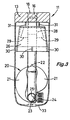
- Figure 3 shows a section through the accumulator rotated by ninety degrees relative to the accumulator shown in Figure 1;
- Figure 4 illustrates the assembly of an accumulator of the type shown in Figure 1; and
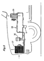
- Figure 5 is a schematic representation of a system using an accumulator of the type shown in Figure1.
-
- A dehydrating accumulator for a refrigeration system embodying the present invention is illustrated in Figure 1. The accumulator has a hollow
external casing 12 of cylindrical shape, having abase 13 that is relatively thicker than its sides and fabricated in aluminium. - An
input hole 14 and anoutput hole 16 are drilled into the base thereby providing access to and from the accumulator. The holes are equidistant from a parallel axis 15 of thecasing 12 and parallel therewith. The external ends ofholes moulded connectors hole 16 is connected to atube 19 that is formed into a U-shape and which extends towards anend 33 of the casing whereafter said tube travels back through most of the length of thecasing 12. An end oftube 19 is firmly located inoutput hole 16 and held securely by solder or by an expansion joint. - Before U-shaped
tube 19 is fitted, afilter unit 20 is attached thereto, consisting of a pair of polyester bags containing drying material, such as synthetic zeolite pellets.Bags 21, attached at 22 by their two ends, are arranged between the two sides of the U-shapedtube 19 and are mounted astride the lower part of thetube 19 as to almost enclose it. In the lower part oftube 19, in the middle of the U, there is a hole into which a filter 24 is snap fitted, having a projection 25 which passes through the twobags 21, thereby sealing them from each other internally. The filter 24 may be of a plastic construction and is configured to filter out impurities such as dust or other particles present in lubrication oil that has reached the bottom of the casing. - At the upper end of
casing 12 there is adiffuser element 26, in the form of an inverted bucket having ahole 27 through whichtube 19 can pass, made in this example from polyamide. Thediffuser element 26 is designed to provide an optimum distribution of the refrigerant (containing lubricating oil) and to make it relatively turbulent as it enters through the input hole 1. - Within the
diffuser element 26, there is aweb 28 withlateral wings 29 between which the free end 19A of thetube 19 terminates. At the point of its widest cross section, thediffuser element 26 has centringfins 30 that spread out radially until they reach the internal surface of thecasing 12. Ahole 32 is provided near to the end of thetube 19 that is located firmly within theoutput hole 16 to draw off excess oil. - The end of the external cylindrical casing that was originally open, is sealed by applying a rotating process to this end. The operation is carried out by a suitable machine with a wheel that permanently deforms the material of the external
cylindrical casing 12, pressing it towards the centre and creating a rounded end which is securely closed and sealed. Thebase 13 of the external cylindrical casing has threadedholes 34, in addition to input andoutput holes 14/16, for the location of fixing bolts. In addition, two furthersmall holes 35 are provided to receive centring dowels. - A procedure for the construction and assembly of the dehydrating accumulator illustrated in Figures 1 to 3, is shown in Figure 4.
- After components making up the accumulator have been prepared, the base of the extruded body is machined at
step 41 to obtainholes - At
step 42, all the internal surfaces of thecasing 12 are degreased, including thebase 13. - At step 43,
bags 21 are firmly attached to thetube 19 by means of their two ends that are soldered atposition 22. - At step 44, the
bags 21 on thetube 19 are closed off by locating filter 24 or its projection 25 inhole 23. The projection also passes through the twobags 21, thereby sealing them from each other. - At
step 45, thediffuser element 26 is assembled onto thetube 19, facilitated by the presence ofwebbing 28, withlateral wings 29 being at a position at which the free end 19A of thetube 19 terminates. - At step 46,
diffuser element 26 is inserted into the casing and is guided by centringfins 30 which spread outwards radially. Thediffuser element 26 is aligned against thebase 13 by means of thefurther distance pieces 31 designed for this purpose. - At
step 47, the end of thetube 19 is secured in theoutput hole 16 or in thebase 13 of thecasing 12 by means of an expansion or soldered joint. With the components fitted into the casing, the casing is closed. - At
step 48, the closed assembly is secured into the chuck of a lathe or similar machine so as to perform the rotation procedure upon the end of thecasing 12. Arounded end 33 is thereby created so as to provide a tight seal. - At
step 49, a final step is performed in which an air-tightness test is carried out. - The fully assembled dehydrating accumulator is fully sealed from the outside and contains a minimum number of component parts. By performing the rotational operation, the end cover and the components used to join the end cover have been eliminated.
- An example of a dehydrating accumulator for a refrigeration system is illustrated in Figure 5. An
accumulator 11 is fitted into an air conditioning system of a motor vehicle. The system also includescompressor 36, acondenser 37, anexpansion unit 38 andevaporator 39. In this system, refrigeration liquid is circulated mixed with oil and the dehydrating accumulator is located in a low pressure part of the system.
Claims (13)
- A dehydrating device (11) for refrigerant, having:characterised in that:an external casing (12) having side walls, a base (13) at a first end and a second end (33), with an input hole (14) and an output hole (16) formed in said base (13), said base being relatively thicker than said side walls;a desiccating filtering means (20);a substantially U-shaped tube (19); anda diffusing means (26), whereina first end of said tube (19) is connected to said output hole (16);a second end of said tube (19) is open and is in juxtaposition with said diffusing means (26); andsaid diffusing means (26) is located in an upper portion of said casing (13),the external casing is an extruded body and the second end (33) of said casing is sealed closed by deforming the material of said casing in a rotational deformation operation.
- A dehydrating device according to claim 1, wherein said filtering means (20) includes bags (21) containing desiccating material.
- A dehydrating device according to claim 2, wherein said bags (21) are fixed to said tube (19) at its lower end.
- A device according to claim 3, wherein said tube (19) has a hole (23) into which is fitted a filter (24) with an extension (25) passing through said desiccating bags (20) thereby sealing them from each other.
- A dehydrating device according to any of claims 1 to 4, wherein the diffusing means (26) is formed substantially like an inverted bucket and has a hole (27) for said tube (19) to pass through.
- A dehydrating device according to any claims 1 to 5, in which the diffuser means (26) has a web (28) with lateral wings (29) within which a free end of said tube (19) is terminated.
- A dehydrating device according to any of claims 1 to 6, in which said diffusing means (26) has central fins (30) spreading outwards until said fins reach the inside of said casing (12).
- A dehydrating device according to any of claims 1 to 7, wherein said input hole (14) and said output hole (16) are drilled parallel to an axis (15) of the casing (12).
- A dehydrating device according to any of claims 1 to 8, wherein said first end of said tube (19) is secured within said output hole (16).
- A dehydrating device according to any of claims 1 to 9, wherein the external ends of said input hole (14) and output hole (16) are fitted with moulded connectors (17 and 18) and are configured to accept input and output pipes.
- A method of fitting a dehydrating device according to any of claims 1 to 10, comprising the steps of:obtaining a hollow external casing (12) comprising an extruded body having side walls, a base (13) at a first end and a second end, said base being relatively thicker than said side walls, and the component parts of an accumulator;forming at least one input hole (14) and one output hole (16) in the base (13) of said casing (12);performing a degreasing stage (42);mounting bags (21) onto the tube (19) by soldering their ends;mounting a filter (24) in a central section of the tube (19) which closes off the other two ends of the bags (21);mounting a diffuser element (26) onto the tube (19);mounting an assembly made up of the tube (19), the bags (21), the filter (24) and the diffuser element (26) into the external casing (12);retaining this assembly within the casing and carrying out said operation of rotational deformation (48) on the open end of the casing so as to create a rounded end (33) forming a tight seal; andperforming an air-tightness test (49).
- A method according to claim 11, wherein the location of the diffuser element (26) over the tube (19) is due to the presence of a web (28) with lateral fixing wings (29).
- A method according to claim 11 or claim 12, wherein the filter (24) is mounted in a central section of the tube (19) by means of inserting its projection (25) into a hole (23) in the tube (19) passing through said bags (21).
Applications Claiming Priority (2)
| Application Number | Priority Date | Filing Date | Title |
|---|---|---|---|
| IT1999MI000822A IT1312193B1 (en) | 1999-04-20 | 1999-04-20 | DEHYDRATOR ACCUMULATOR FOR REFRIGERATION CIRCUITS AND ASSEMBLY PROCEDURE |
| ITMI990822 | 1999-04-20 |
Publications (3)
| Publication Number | Publication Date |
|---|---|
| EP1046872A2 EP1046872A2 (en) | 2000-10-25 |
| EP1046872A3 EP1046872A3 (en) | 2001-02-07 |
| EP1046872B1 true EP1046872B1 (en) | 2005-01-26 |
Family
ID=11382774
Family Applications (1)
| Application Number | Title | Priority Date | Filing Date |
|---|---|---|---|
| EP00301678A Expired - Lifetime EP1046872B1 (en) | 1999-04-20 | 2000-03-01 | Dehydrating accumulator for refrigeration systems and method of assembling the same |
Country Status (6)
| Country | Link |
|---|---|
| US (1) | US6442965B1 (en) |
| EP (1) | EP1046872B1 (en) |
| AT (1) | ATE288059T1 (en) |
| DE (1) | DE60017629T2 (en) |
| ES (1) | ES2235775T3 (en) |
| IT (1) | IT1312193B1 (en) |
Families Citing this family (15)
| Publication number | Priority date | Publication date | Assignee | Title |
|---|---|---|---|---|
| DE10058513A1 (en) * | 2000-11-24 | 2002-06-20 | Obrist Engineering Gmbh Lusten | collector |
| US6536230B2 (en) * | 2001-01-22 | 2003-03-25 | Delphi Technologies, Inc. | A/D baffle for gas pressure pulsation reduction |
| ITMI20010655U1 (en) * | 2001-12-14 | 2003-06-16 | Ti Automotive Cisliano S R L | DEHYDRATOR ACCUMULATOR FOR REFRIGERATION CIRCUITS WITH SIMPLIFIED STRUCTURE |
| DE10237178B4 (en) * | 2002-08-14 | 2007-10-18 | Hansa Metallwerke Ag | Accumulator for a working on the "Orifice" principle air conditioning, in particular vehicle air conditioning |
| DE10237179B4 (en) * | 2002-08-14 | 2007-08-30 | Hansa Metallwerke Ag | Accumulator for a working on the "Orifice" principle air conditioning, in particular vehicle air conditioning |
| DE10324955B4 (en) * | 2003-06-03 | 2010-04-29 | Audi Ag | Air conditioning for heating and cooling a room |
| US7287399B2 (en) | 2004-02-17 | 2007-10-30 | Obrist Engineering Gmbh | Collector for the liquid phase of the working medium of an air-conditioning system |
| DE102006022024A1 (en) * | 2006-05-10 | 2007-11-15 | Behr Gmbh & Co. Kg | Air conditioning system`s accumulator for use in motor vehicle, has pipe with refrigerant-inlet-sided end by which gaseous refrigerant is reached into pipe, where end is arranged in increased area |
| DE102007033149A1 (en) * | 2007-07-13 | 2009-01-15 | Behr Gmbh & Co. Kg | Accumulator, in particular for an air conditioning system, with dirt trap |
| DE102008028852A1 (en) * | 2008-06-19 | 2009-12-24 | Behr Gmbh & Co. Kg | Refrigerant collector with liquid separator |
| CN103277952B (en) * | 2013-05-22 | 2015-07-08 | 浙江盾安冷链系统有限公司 | Gas-liquid separator |
| CN106969560A (en) * | 2015-12-22 | 2017-07-21 | 翰昂汽车零部件有限公司 | For the device for the liquid refrigerant for separating and storing refrigerant-cycle systems |
| DE102024118469A1 (en) * | 2024-06-28 | 2025-12-31 | Mahle International Gmbh | Accumulator for a refrigerant circuit |
| DE102024118465A1 (en) * | 2024-06-28 | 2025-12-31 | Mahle International Gmbh | Accumulator for a refrigerant circuit with a recess in the base |
| DE102024118467A1 (en) * | 2024-06-28 | 2025-12-31 | Mahle International Gmbh | Storage container for a refrigerant circuit |
Family Cites Families (13)
| Publication number | Priority date | Publication date | Assignee | Title |
|---|---|---|---|---|
| US4270934A (en) * | 1978-06-05 | 1981-06-02 | General Motors Corporation | Universal internal tube accumulator |
| US4474035A (en) * | 1983-12-23 | 1984-10-02 | Ford Motor Company | Domed accumulator for automotive air conditioning system |
| US4675971A (en) * | 1985-12-03 | 1987-06-30 | Michigan Special Products, Inc. | Desiccant assembly for refrigeration circuit and method |
| US5048309A (en) * | 1987-12-30 | 1991-09-17 | Carlisle Jr Billy M | Universal accumulator |
| US4835986A (en) * | 1987-12-30 | 1989-06-06 | Carlisle Jr Billy M | Universal accumulator |
| US4994185A (en) * | 1989-03-23 | 1991-02-19 | Multiform Desiccants, Inc. | Combined heat shielding and bonding device for adsorbent packet in refrigerant receiver |
| US5184479A (en) * | 1991-12-23 | 1993-02-09 | Ford Motor Company | Accumulator for vehicle air conditioning system |
| US5282370A (en) * | 1992-05-07 | 1994-02-01 | Fayette Tubular Technology Corporation | Air-conditioning system accumulator and method of making same |
| US5471854A (en) * | 1994-06-16 | 1995-12-05 | Automotive Fluid Systems, Inc. | Accumulator for an air conditioning system |
| US5693124A (en) * | 1995-09-13 | 1997-12-02 | Multisorb Technologies, Inc. | Accumulator desiccant bag |
| US5660058A (en) * | 1995-11-03 | 1997-08-26 | Ford Motor Company | Accumulator for vehicle air conditioning system |
| US5701758A (en) * | 1996-01-30 | 1997-12-30 | Haramoto; Cary | Refrigeration system accumulating vessel having a brazed, metal-clad deflector |
| US5746065A (en) * | 1996-08-21 | 1998-05-05 | Automotive Fluid Systems, Inc. | Accumulator deflector connection and method |
-
1999
- 1999-04-20 IT IT1999MI000822A patent/IT1312193B1/en active
-
2000
- 2000-03-01 EP EP00301678A patent/EP1046872B1/en not_active Expired - Lifetime
- 2000-03-01 AT AT00301678T patent/ATE288059T1/en not_active IP Right Cessation
- 2000-03-01 DE DE60017629T patent/DE60017629T2/en not_active Expired - Lifetime
- 2000-03-01 ES ES00301678T patent/ES2235775T3/en not_active Expired - Lifetime
- 2000-04-20 US US09/552,845 patent/US6442965B1/en not_active Expired - Fee Related
Also Published As
| Publication number | Publication date |
|---|---|
| ITMI990822A1 (en) | 2000-10-20 |
| DE60017629T2 (en) | 2005-12-22 |
| IT1312193B1 (en) | 2002-04-09 |
| EP1046872A3 (en) | 2001-02-07 |
| US6442965B1 (en) | 2002-09-03 |
| EP1046872A2 (en) | 2000-10-25 |
| DE60017629D1 (en) | 2005-03-03 |
| ES2235775T3 (en) | 2005-07-16 |
| ATE288059T1 (en) | 2005-02-15 |
Similar Documents
| Publication | Publication Date | Title |
|---|---|---|
| US6442965B1 (en) | Dehydrating accumulator for refrigeration systems | |
| US5515696A (en) | Receiver/drier/filter assembly | |
| US5628206A (en) | Refrigerant condenser | |
| US5596882A (en) | Receiver for refrigerant and method of making same | |
| KR100232917B1 (en) | Accumulator deflector connection and accumulator manufacturing method comprising the deflector connection | |
| US5179780A (en) | Universal seamless receiver-dehydrator assembly for an automotive air conditioning system | |
| EP0800044A2 (en) | Drier/accumulator for refrigerant system and method of making same | |
| CA2159143C (en) | Heat exchanger with integral filter/drier cartridge | |
| US20030079497A1 (en) | Baffle connection for an accumulator and related method of manufacturing | |
| US5471854A (en) | Accumulator for an air conditioning system | |
| US5557945A (en) | Refrigerant compressor and refrigeration system incorporating same | |
| US4866951A (en) | Vehicle air conditioning accumulator with adjustable connector | |
| US6389843B2 (en) | Receiver dryer with bottom inlet | |
| US5787573A (en) | Method of making air conditioner receiver dryer | |
| US5425250A (en) | Receiver/dryer | |
| EP1319909A2 (en) | Accumulator dehydrator for cooling circuits with a simplified structure | |
| JP2012132665A (en) | Assembly of two-phase heat exchanger and header | |
| EP4417901A1 (en) | Perpendicular flow type filter element as well as an air conditioning system with the same | |
| KR200369548Y1 (en) | Structure of receiver drier tank for air conditioner | |
| KR20010076284A (en) | Accumulator | |
| JP3925426B2 (en) | Refrigeration cycle equipment | |
| KR100537225B1 (en) | Structure and method for installation of air conditioner receiver drier tank and fixity | |
| KR101851659B1 (en) | Method and structure for assembling of receiver drier tank and cap | |
| US20240230186A9 (en) | Fluid collector | |
| KR100524879B1 (en) | Condenser system and it's processing method |
Legal Events
| Date | Code | Title | Description |
|---|---|---|---|
| PUAI | Public reference made under article 153(3) epc to a published international application that has entered the european phase |
Free format text: ORIGINAL CODE: 0009012 |
|
| AK | Designated contracting states |
Kind code of ref document: A2 Designated state(s): AT BE CH CY DE DK ES FI FR GB GR IE IT LI LU MC NL PT SE |
|
| AX | Request for extension of the european patent |
Free format text: AL;LT;LV;MK;RO;SI |
|
| PUAL | Search report despatched |
Free format text: ORIGINAL CODE: 0009013 |
|
| AK | Designated contracting states |
Kind code of ref document: A3 Designated state(s): AT BE CH CY DE DK ES FI FR GB GR IE IT LI LU MC NL PT SE |
|
| AX | Request for extension of the european patent |
Free format text: AL;LT;LV;MK;RO;SI |
|
| 17P | Request for examination filed |
Effective date: 20010302 |
|
| AKX | Designation fees paid |
Free format text: AT BE CH CY DE DK ES FI FR GB GR IE IT LI LU MC NL PT SE |
|
| 17Q | First examination report despatched |
Effective date: 20030102 |
|
| GRAP | Despatch of communication of intention to grant a patent |
Free format text: ORIGINAL CODE: EPIDOSNIGR1 |
|
| RTI1 | Title (correction) |
Free format text: DEHYDRATING ACCUMULATOR FOR REFRIGERATION SYSTEMS AND METHOD OF ASSEMBLING THE SAME |
|
| RAP1 | Party data changed (applicant data changed or rights of an application transferred) |
Owner name: TI GROUP AUTOMOTIVE SYSTEMS LIMITED |
|
| GRAS | Grant fee paid |
Free format text: ORIGINAL CODE: EPIDOSNIGR3 |
|
| GRAA | (expected) grant |
Free format text: ORIGINAL CODE: 0009210 |
|
| AK | Designated contracting states |
Kind code of ref document: B1 Designated state(s): AT BE CH CY DE DK ES FI FR GB GR IE IT LI LU MC NL PT SE |
|
| PG25 | Lapsed in a contracting state [announced via postgrant information from national office to epo] |
Ref country code: LI Free format text: LAPSE BECAUSE OF FAILURE TO SUBMIT A TRANSLATION OF THE DESCRIPTION OR TO PAY THE FEE WITHIN THE PRESCRIBED TIME-LIMIT Effective date: 20050126 Ref country code: FI Free format text: LAPSE BECAUSE OF FAILURE TO SUBMIT A TRANSLATION OF THE DESCRIPTION OR TO PAY THE FEE WITHIN THE PRESCRIBED TIME-LIMIT Effective date: 20050126 Ref country code: NL Free format text: LAPSE BECAUSE OF FAILURE TO SUBMIT A TRANSLATION OF THE DESCRIPTION OR TO PAY THE FEE WITHIN THE PRESCRIBED TIME-LIMIT Effective date: 20050126 Ref country code: CH Free format text: LAPSE BECAUSE OF FAILURE TO SUBMIT A TRANSLATION OF THE DESCRIPTION OR TO PAY THE FEE WITHIN THE PRESCRIBED TIME-LIMIT Effective date: 20050126 Ref country code: BE Free format text: LAPSE BECAUSE OF FAILURE TO SUBMIT A TRANSLATION OF THE DESCRIPTION OR TO PAY THE FEE WITHIN THE PRESCRIBED TIME-LIMIT Effective date: 20050126 Ref country code: AT Free format text: LAPSE BECAUSE OF FAILURE TO SUBMIT A TRANSLATION OF THE DESCRIPTION OR TO PAY THE FEE WITHIN THE PRESCRIBED TIME-LIMIT Effective date: 20050126 |
|
| REG | Reference to a national code |
Ref country code: GB Ref legal event code: FG4D |
|
| REG | Reference to a national code |
Ref country code: CH Ref legal event code: EP |
|
| REG | Reference to a national code |
Ref country code: IE Ref legal event code: FG4D |
|
| PG25 | Lapsed in a contracting state [announced via postgrant information from national office to epo] |
Ref country code: CY Free format text: LAPSE BECAUSE OF FAILURE TO SUBMIT A TRANSLATION OF THE DESCRIPTION OR TO PAY THE FEE WITHIN THE PRESCRIBED TIME-LIMIT Effective date: 20050301 Ref country code: IE Free format text: LAPSE BECAUSE OF NON-PAYMENT OF DUE FEES Effective date: 20050301 Ref country code: IT Free format text: LAPSE BECAUSE OF NON-PAYMENT OF DUE FEES Effective date: 20050301 |
|
| REF | Corresponds to: |
Ref document number: 60017629 Country of ref document: DE Date of ref document: 20050303 Kind code of ref document: P |
|
| PG25 | Lapsed in a contracting state [announced via postgrant information from national office to epo] |
Ref country code: MC Free format text: LAPSE BECAUSE OF NON-PAYMENT OF DUE FEES Effective date: 20050331 |
|
| PG25 | Lapsed in a contracting state [announced via postgrant information from national office to epo] |
Ref country code: SE Free format text: LAPSE BECAUSE OF FAILURE TO SUBMIT A TRANSLATION OF THE DESCRIPTION OR TO PAY THE FEE WITHIN THE PRESCRIBED TIME-LIMIT Effective date: 20050426 Ref country code: GR Free format text: LAPSE BECAUSE OF FAILURE TO SUBMIT A TRANSLATION OF THE DESCRIPTION OR TO PAY THE FEE WITHIN THE PRESCRIBED TIME-LIMIT Effective date: 20050426 Ref country code: GB Free format text: LAPSE BECAUSE OF NON-PAYMENT OF DUE FEES Effective date: 20050426 Ref country code: DK Free format text: LAPSE BECAUSE OF FAILURE TO SUBMIT A TRANSLATION OF THE DESCRIPTION OR TO PAY THE FEE WITHIN THE PRESCRIBED TIME-LIMIT Effective date: 20050426 |
|
| NLV1 | Nl: lapsed or annulled due to failure to fulfill the requirements of art. 29p and 29m of the patents act | ||
| REG | Reference to a national code |
Ref country code: ES Ref legal event code: FG2A Ref document number: 2235775 Country of ref document: ES Kind code of ref document: T3 |
|
| REG | Reference to a national code |
Ref country code: CH Ref legal event code: PL |
|
| PLBE | No opposition filed within time limit |
Free format text: ORIGINAL CODE: 0009261 |
|
| STAA | Information on the status of an ep patent application or granted ep patent |
Free format text: STATUS: NO OPPOSITION FILED WITHIN TIME LIMIT |
|
| ET | Fr: translation filed | ||
| GBPC | Gb: european patent ceased through non-payment of renewal fee |
Effective date: 20050426 |
|
| REG | Reference to a national code |
Ref country code: IE Ref legal event code: MM4A |
|
| 26N | No opposition filed |
Effective date: 20051027 |
|
| PG25 | Lapsed in a contracting state [announced via postgrant information from national office to epo] |
Ref country code: PT Free format text: LAPSE BECAUSE OF NON-PAYMENT OF DUE FEES Effective date: 20050626 |
|
| PGRI | Patent reinstated in contracting state [announced from national office to epo] |
Ref country code: IT Effective date: 20091201 |
|
| PGFP | Annual fee paid to national office [announced via postgrant information from national office to epo] |
Ref country code: IT Payment date: 20120326 Year of fee payment: 13 |
|
| PGFP | Annual fee paid to national office [announced via postgrant information from national office to epo] |
Ref country code: DE Payment date: 20130327 Year of fee payment: 14 Ref country code: ES Payment date: 20130326 Year of fee payment: 14 Ref country code: FR Payment date: 20130405 Year of fee payment: 14 |
|
| REG | Reference to a national code |
Ref country code: DE Ref legal event code: R119 Ref document number: 60017629 Country of ref document: DE |
|
| REG | Reference to a national code |
Ref country code: FR Ref legal event code: ST Effective date: 20141128 |
|
| REG | Reference to a national code |
Ref country code: DE Ref legal event code: R119 Ref document number: 60017629 Country of ref document: DE Effective date: 20141001 |
|
| PG25 | Lapsed in a contracting state [announced via postgrant information from national office to epo] |
Ref country code: DE Free format text: LAPSE BECAUSE OF NON-PAYMENT OF DUE FEES Effective date: 20141001 Ref country code: FR Free format text: LAPSE BECAUSE OF NON-PAYMENT OF DUE FEES Effective date: 20140331 |
|
| PG25 | Lapsed in a contracting state [announced via postgrant information from national office to epo] |
Ref country code: IT Free format text: LAPSE BECAUSE OF NON-PAYMENT OF DUE FEES Effective date: 20140301 |
|
| REG | Reference to a national code |
Ref country code: ES Ref legal event code: FD2A Effective date: 20150424 |
|
| PG25 | Lapsed in a contracting state [announced via postgrant information from national office to epo] |
Ref country code: ES Free format text: LAPSE BECAUSE OF NON-PAYMENT OF DUE FEES Effective date: 20140302 |