EP1046850A2 - Marine hose - Google Patents
Marine hose Download PDFInfo
- Publication number
- EP1046850A2 EP1046850A2 EP20000108040 EP00108040A EP1046850A2 EP 1046850 A2 EP1046850 A2 EP 1046850A2 EP 20000108040 EP20000108040 EP 20000108040 EP 00108040 A EP00108040 A EP 00108040A EP 1046850 A2 EP1046850 A2 EP 1046850A2
- Authority
- EP
- European Patent Office
- Prior art keywords
- outermost layer
- hose
- marine hose
- marking lamp
- marking
- Prior art date
- Legal status (The legal status is an assumption and is not a legal conclusion. Google has not performed a legal analysis and makes no representation as to the accuracy of the status listed.)
- Granted
Links
Images

Classifications
-
- F—MECHANICAL ENGINEERING; LIGHTING; HEATING; WEAPONS; BLASTING
- F16—ENGINEERING ELEMENTS AND UNITS; GENERAL MEASURES FOR PRODUCING AND MAINTAINING EFFECTIVE FUNCTIONING OF MACHINES OR INSTALLATIONS; THERMAL INSULATION IN GENERAL
- F16L—PIPES; JOINTS OR FITTINGS FOR PIPES; SUPPORTS FOR PIPES, CABLES OR PROTECTIVE TUBING; MEANS FOR THERMAL INSULATION IN GENERAL
- F16L11/00—Hoses, i.e. flexible pipes
- F16L11/04—Hoses, i.e. flexible pipes made of rubber or flexible plastics
- F16L11/12—Hoses, i.e. flexible pipes made of rubber or flexible plastics with arrangements for particular purposes, e.g. specially profiled, with protecting layer, heated, electrically conducting
- F16L11/133—Hoses, i.e. flexible pipes made of rubber or flexible plastics with arrangements for particular purposes, e.g. specially profiled, with protecting layer, heated, electrically conducting buoyant
Definitions
- the present invention relates to a marine hose used for loading and unloading fluid such as crude oil between a tank on the land and an oil tanker on the sea, more particularly to a marine hose which is designed so as to easily recognize a hose line floating on the sea even in the night.
- Loading and unloading of fluid such as crude oil between a tanker on the sea and an oil tank on the land are generally performed by connecting a plurality of marine hoses formed to a predetermined length over a distance between an oil tanker and a an oil tank ranging several hundred meters to several kilometers.
- the marine hose is generally used in a state where the marine hose is floating on the sea, and hence the marine hose line must be recognized by ships navigating on the sea night and day by any marking means so that the ships can not touch and hitch the marine hose.
- the surroundings of the marine hose line are pitch-dark.
- the marine hose line is not always straight and may meander due to waves. As a result, it is very difficult to recognize the marine hose line.
- the structure in which the marking lamps are fitted to the flange of the marine hose involves a problem that intervals between the marking lamps are large and it is difficult to recognize the hose line to be a line-shape.
- the marking lamps have a structure that they protrude to the above via a pole, the marking lamps are apt to be damaged when they collide with the ships and the like.
- the marking lamps are apt to be damaged when they collide with the ships and the like.
- the hose crosses the other owing to waves and the like, and the adjacent hose may be damaged by the marking lamp.
- the conventional marking lamp since the conventional marking lamp has a complicated structure and shape, it is expensive. Since the conventional marking lamp emits light by a battery, replacement of the battery is needed at regular intervals, thus increasing maintenance costs.
- the primary object of the present invention is to provide a marine hose which enables easy recognition of a hose line floating on the sea even in the night.
- Another object of the present invention is to provide a marine hose which makes it unnecessary to replace a battery with new one or to charge it and is capable of reducing maintenance costs.
- Still further another object of the present invention is to provide a marine hose which is capable of preventing a marking lamp from being damaged due to a touch to a ship and the like and a crossing of a hose body.
- the marine hose of the present invention to achieve the foregoing objects has a feature in that a buoyancy material layer is buried in a hose body having a multi-layered structure, and a marking lamp is fitted to a surface of the outermost layer of the hose body.
- the marine hose of the present invention adopts the structure in which the marking lamp is fitted to the surface of the outermost layer of the hose body, a plurality of marking lamps can be fitted in the longitudinal direction of the hose, and hence the hose body can easily be recognized to be a line shape even in the night.
- a marking lamp which emits light by itself without any aid from others hereinafter referred to as a self-light emission
- replacement and charging of a battery become unnecessary resulting in reduction of maintenance costs.
- the above-described marking lamp is fitted to the surface of the outermost layer of the hose body via a fitting member such as a supporting plate, buried inside the outermost layer. Or, alternatively, the marking lamp is fitted to the surface of the outermost layer via adhesive. Therefore, a fitting operation is simplified and the fitting member never damages other hoses.
- a protection cover made of an elastic body is fitted to the surface of the outermost rubber layer so as to put the marking lamp therebetween, the marking lamp can be sufficiently protected, and hence the marking lamp is never damaged when the hose is withdrawn to the land or when the ship touches the hose.
- Such protection cover can be also fitted to the surface of the outermost layer by adhesive.
- a curvature radius of a plane of the protection cover to be adhered to the outermost surface before adhesion to the outermost layer should be made to be set smaller than that of the surface of the outermost layer.
- the upper surface of the protection cover should be formed so as to be higher than that of the marking lamp.
- the marking lamp can be cleaned simply by replacing the transparent resin film with new one when the surface of the marking lamp becomes dirty by droppings of birds and the like.
- Figs. 1 to 4 show a marine hose in which the present invention is embodied.
- the marine hose of this embodiment has a structure in which coupling flanges 2a and 2b are integrally provided on both end portions of the tube-shaped hose body 1 having a multi-layered structure.
- the hose body 1 has a structure in which a buoyancy material layer 11 is laminated between an outermost layer 1a and an inner tube layer 12.
- the outermost layer 1a can be constituted by a rubber layer having a reinforcement material buried therein.
- the inner tube layer 12 can be constituted by a rubber layer excellent in oil resistance.
- the buoyancy material layer 11 is made of a low density substance and simply gives a buoyancy to the whole of the hose.
- the marking lamp 3 is fitted to the surface of the outermost rubber layer 1a in the vicinity of the coupling flanges 2a and 2b of the hose body 1 via the fitting member 4, the marking lamp 3 being freely detachable from the surface of the outermost rubber layer 1a.
- the marking lamp 3 has a structure that a solar cell 6 is accommodated inside a resin cover 5 and a pair of lights 7 are disposed the side walls of the resin cover 5. At least a portion of the resin cover 5, which corresponds to the solar cell 6 and the lights 7, is transparent.
- the solar cell 6 converts solar energy which is incident thereonto through the resin cover 5, to electric energy and stores the energy therein.
- the light 7 emits light by the energy stored in the solar cell 6.
- the marking lamp 3 comprises an optical sensor (not shown) for sensing brightness, and turns off the light 7 in the day time based on a sensing result of the optical sensor and turns on the light 7 only in the night. For this reason, the marking lamp 3 is at least capable of performing a self-light emission in the night based on energy supplied from the solar cell 6. As a matter of course, the marking lamp 3 may be always turned on based on energy supplied from the solar cell 6.
- the fitting member 4 of the marking lamp 3 is constituted by a supporting plate 9 buried inside the outermost layer 1a and a fastening member 10 such as bolt and nut.
- the outermost layer 1a is put between a flange portion 5a of the resin cover 5, which constitutes the marking lamp 3, and the supporting plate 9 located on a rear surface of the outermost layer 1a.
- the flange portion 5a and the supporting plate 9 are fastened to each other by the fastening member 10.
- the fitting member 4 may be used in combination with adhesive.
- Protection covers 13a and 13b made of a rubber material are arranged on the right and left sides of the marking lamp 3.
- the protection covers 13a and 13b cover both sides of the resin cover 5.
- These protection covers 13a and 13b are fitted to the surface of the outermost layer 1a via a rubber sheet 8.
- the rubber sheet 8 and the protection covers 13a and 13b are combined to each other, and the rubber sheet 8 has a hole in the center portion for the marking lamp 3 to be disposed.
- the protection covers 13a and 13b comprise respectively a concave portion 14 which mates with the flange portion 5a, and the protection covers 13a and 13b contact tightly to both sides of the resin cover 5, respectively, thus increasing a protection effect.
- the protection covers 13a and 13b it is not necessary for the protection covers 13a and 13b to contact tightly to both sides of the resin cover 5.
- the upper planes of the protection covers 13a and 13b are formed so as to be positioned higher than the upper plane of the resin cover 5.
- the marine hose 1 is designed so that the marking lamp 3 is not damaged when the marine hose 1 is rolled on the land and even when a ship touches the hose body 1.
- a step difference t between the upper planes of the protection covers 13a and 13b and the upper plane of the resin cover 5 should be set to about several millimeters.
- a curvature radius of the fitting planes 13x of the protection covers 13a and 13b is formed to be somewhat smaller than that of the outermost layer 1a.
- the fitting plane 13x of each of the protection covers 13a and 13b is adhered to the surface of the outermost layer 1a while creating a compressive strain on a non-adhered plane side of each of the protection covers 13a and 13b by widening the fitting plane 13x of each protection covers 13a and 13b toward the outer periphery of the outermost layer 1a.
- an adhesive strength of the fitting plane 13x to the surface of the outermost layer 1a is increased, and occurrence of ozone cracks is prevented.
- the surface of the resin cover 5 sometimes becomes dirty by droppings of birds and other foreign matters.
- the surface of the resin cover 5 is sometimes damaged.
- an absorption efficiency of solar energy by the solar cell 6 may be degraded, thus reducing brightness of the light 7. Accordingly, in order to prevent this, it is possible to adhere a transparent resin film which can be repapered periodically.
- the marking lamp 3 since the marking lamp 3 is fitted to the surface of the outermost layer 1a of the hose body 1, the plurality of marking lamps 3 can be fitted thereto along the longitudinal direction of the hose so as to be arrayed on a straight line, unlike the case in which the marking lamp is fitted to a connection flange of the marine hose as conventional. Accordingly, the hose body 1 of the marine hose can be easily recognized to be a line shape even in the night.
- the marine hose comprises the self-light emission type marking lamp 3 utilizing energy stored by the solar cell 6, replacement of batteries is unnecessary, thus reducing maintenance costs significantly.
- the marking lamp 3 is fitted to the surface of the outermost layer 1a of the hose body 1 through the fitting member 4 composed of the supporting plate 9 and the fastening member 10. Or, alternatively, the marking lamp 3 is fitted thereto via adhesive.
- the fitting operation is simple, and the fitting member does not damage other marine hoses.
- the marking lamp 3 fitted to the surface of the outermost layer 1a is protected by the protection covers 13a and 13b made of an elastic body, the marking lamp 3 is not damaged when the hose is placed and rolled on the land and when a ship touches the hose.
Landscapes
- Engineering & Computer Science (AREA)
- General Engineering & Computer Science (AREA)
- Mechanical Engineering (AREA)
- Rigid Pipes And Flexible Pipes (AREA)
Abstract
Description
- The present invention relates to a marine hose used for loading and unloading fluid such as crude oil between a tank on the land and an oil tanker on the sea, more particularly to a marine hose which is designed so as to easily recognize a hose line floating on the sea even in the night.
- Loading and unloading of fluid such as crude oil between a tanker on the sea and an oil tank on the land are generally performed by connecting a plurality of marine hoses formed to a predetermined length over a distance between an oil tanker and a an oil tank ranging several hundred meters to several kilometers. Nevertheless, the marine hose is generally used in a state where the marine hose is floating on the sea, and hence the marine hose line must be recognized by ships navigating on the sea night and day by any marking means so that the ships can not touch and hitch the marine hose. Particularly, in the night, the surroundings of the marine hose line are pitch-dark. Moreover, the marine hose line is not always straight and may meander due to waves. As a result, it is very difficult to recognize the marine hose line.
- Accordingly, a marine hose taking a structure in which a marking lamps are fitted to a flange thereof has been proposed as disclosed in Japanese Utility Model Publication No. 3-56157.
- Nevertheless, the structure in which the marking lamps are fitted to the flange of the marine hose involves a problem that intervals between the marking lamps are large and it is difficult to recognize the hose line to be a line-shape.
- Moreover, since the marking lamps have a structure that they protrude to the above via a pole, the marking lamps are apt to be damaged when they collide with the ships and the like. In addition, when two hose lines are provided in parallel, the hose crosses the other owing to waves and the like, and the adjacent hose may be damaged by the marking lamp.
- Furthermore, since the conventional marking lamp has a complicated structure and shape, it is expensive. Since the conventional marking lamp emits light by a battery, replacement of the battery is needed at regular intervals, thus increasing maintenance costs.
- The primary object of the present invention is to provide a marine hose which enables easy recognition of a hose line floating on the sea even in the night.
- Another object of the present invention is to provide a marine hose which makes it unnecessary to replace a battery with new one or to charge it and is capable of reducing maintenance costs.
- Still further another object of the present invention is to provide a marine hose which is capable of preventing a marking lamp from being damaged due to a touch to a ship and the like and a crossing of a hose body.
- The marine hose of the present invention to achieve the foregoing objects has a feature in that a buoyancy material layer is buried in a hose body having a multi-layered structure, and a marking lamp is fitted to a surface of the outermost layer of the hose body.
- As described above, since the marine hose of the present invention adopts the structure in which the marking lamp is fitted to the surface of the outermost layer of the hose body, a plurality of marking lamps can be fitted in the longitudinal direction of the hose, and hence the hose body can easily be recognized to be a line shape even in the night.
- Furthermore, if a marking lamp which emits light by itself without any aid from others (hereinafter referred to as a self-light emission), based on energy stored in a solar cell is used, replacement and charging of a battery become unnecessary resulting in reduction of maintenance costs.
- The above-described marking lamp is fitted to the surface of the outermost layer of the hose body via a fitting member such as a supporting plate, buried inside the outermost layer. Or, alternatively, the marking lamp is fitted to the surface of the outermost layer via adhesive. Therefore, a fitting operation is simplified and the fitting member never damages other hoses.
- Furthermore, when a protection cover made of an elastic body is fitted to the surface of the outermost rubber layer so as to put the marking lamp therebetween, the marking lamp can be sufficiently protected, and hence the marking lamp is never damaged when the hose is withdrawn to the land or when the ship touches the hose. Such protection cover can be also fitted to the surface of the outermost layer by adhesive. To improve adhesive properties and crack-resistance properties of the protection cover, a curvature radius of a plane of the protection cover to be adhered to the outermost surface before adhesion to the outermost layer should be made to be set smaller than that of the surface of the outermost layer. Moreover, to enhance a protection effect obtained by the protection cover, the upper surface of the protection cover should be formed so as to be higher than that of the marking lamp.
- Moreover, if the surface of the marking lamp is covered with a transparent resin film which is freely detached therefrom, the marking lamp can be cleaned simply by replacing the transparent resin film with new one when the surface of the marking lamp becomes dirty by droppings of birds and the like.
- For a more complete understanding of the present invention and the advantages thereof, reference is now made to the following description taken in conjunction with the accompanying drawings, in which;
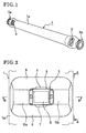
- Fig. 1 is a perspective view showing a marine hose according to an embodiment of the present invention;
- Fig. 2 is an enlarged plan view of a marking lamp shown in Fig. 1;
- Fig. 3 is a side view taken along the line A-A of Fig. 2; and
- Fig. 4 is a section view taken along the line B-B of Fig. 2.
-
- Figs. 1 to 4 show a marine hose in which the present invention is embodied. The marine hose of this embodiment has a structure in which
coupling flanges shaped hose body 1 having a multi-layered structure. As shown in Fig. 4, thehose body 1 has a structure in which abuoyancy material layer 11 is laminated between anoutermost layer 1a and aninner tube layer 12. Theoutermost layer 1a can be constituted by a rubber layer having a reinforcement material buried therein. Theinner tube layer 12 can be constituted by a rubber layer excellent in oil resistance. Furthermore, it is sufficient that thebuoyancy material layer 11 is made of a low density substance and simply gives a buoyancy to the whole of the hose. - The marking
lamp 3 is fitted to the surface of theoutermost rubber layer 1a in the vicinity of thecoupling flanges hose body 1 via thefitting member 4, the markinglamp 3 being freely detachable from the surface of theoutermost rubber layer 1a. - The marking
lamp 3 has a structure that asolar cell 6 is accommodated inside aresin cover 5 and a pair oflights 7 are disposed the side walls of theresin cover 5. At least a portion of theresin cover 5, which corresponds to thesolar cell 6 and thelights 7, is transparent. Thesolar cell 6 converts solar energy which is incident thereonto through theresin cover 5, to electric energy and stores the energy therein. On the other hand, thelight 7 emits light by the energy stored in thesolar cell 6. The markinglamp 3 comprises an optical sensor (not shown) for sensing brightness, and turns off thelight 7 in the day time based on a sensing result of the optical sensor and turns on thelight 7 only in the night. For this reason, the markinglamp 3 is at least capable of performing a self-light emission in the night based on energy supplied from thesolar cell 6. As a matter of course, the markinglamp 3 may be always turned on based on energy supplied from thesolar cell 6. - The
fitting member 4 of the markinglamp 3 is constituted by a supportingplate 9 buried inside theoutermost layer 1a and a fasteningmember 10 such as bolt and nut. In other words, theoutermost layer 1a is put between aflange portion 5a of theresin cover 5, which constitutes the markinglamp 3, and the supportingplate 9 located on a rear surface of theoutermost layer 1a. Theflange portion 5a and the supportingplate 9 are fastened to each other by the fasteningmember 10. - Note that it is possible to directly fit the
flange portion 5a of theresin cover 5 constituting the markinglamp 3 to the surface of theoutermost layer 1a via adhesive. Moreover, thefitting member 4 may be used in combination with adhesive. - Protection covers 13a and 13b made of a rubber material are arranged on the right and left sides of the marking
lamp 3. The protection covers 13a and 13b cover both sides of theresin cover 5. These protection covers 13a and 13b are fitted to the surface of theoutermost layer 1a via arubber sheet 8. Therubber sheet 8 and the protection covers 13a and 13b are combined to each other, and therubber sheet 8 has a hole in the center portion for the markinglamp 3 to be disposed. The protection covers 13a and 13b comprise respectively aconcave portion 14 which mates with theflange portion 5a, and the protection covers 13a and 13b contact tightly to both sides of theresin cover 5, respectively, thus increasing a protection effect. However, it is not necessary for the protection covers 13a and 13b to contact tightly to both sides of theresin cover 5. The upper planes of the protection covers 13a and 13b are formed so as to be positioned higher than the upper plane of theresin cover 5. Themarine hose 1 is designed so that the markinglamp 3 is not damaged when themarine hose 1 is rolled on the land and even when a ship touches thehose body 1. A step difference t between the upper planes of the protection covers 13a and 13b and the upper plane of theresin cover 5 should be set to about several millimeters. - A curvature radius of the
fitting planes 13x of the protection covers 13a and 13b is formed to be somewhat smaller than that of theoutermost layer 1a. When the protection covers 13a and 13b are fitted to the surface of theoutermost layer 1a via the adhesive materials, thefitting plane 13x of each of the protection covers 13a and 13b is adhered to the surface of theoutermost layer 1a while creating a compressive strain on a non-adhered plane side of each of the protection covers 13a and 13b by widening thefitting plane 13x of each protection covers 13a and 13b toward the outer periphery of theoutermost layer 1a. Thus, an adhesive strength of thefitting plane 13x to the surface of theoutermost layer 1a is increased, and occurrence of ozone cracks is prevented. - The surface of the
resin cover 5 sometimes becomes dirty by droppings of birds and other foreign matters. When the hose is rolled on the land, or when a ship touches the hose, the surface of theresin cover 5 is sometimes damaged. In such cases, an absorption efficiency of solar energy by thesolar cell 6 may be degraded, thus reducing brightness of thelight 7. Accordingly, in order to prevent this, it is possible to adhere a transparent resin film which can be repapered periodically. - In the above-described marine hose, since the marking
lamp 3 is fitted to the surface of theoutermost layer 1a of thehose body 1, the plurality of markinglamps 3 can be fitted thereto along the longitudinal direction of the hose so as to be arrayed on a straight line, unlike the case in which the marking lamp is fitted to a connection flange of the marine hose as conventional. Accordingly, thehose body 1 of the marine hose can be easily recognized to be a line shape even in the night. - Since the marine hose comprises the self-light emission
type marking lamp 3 utilizing energy stored by thesolar cell 6, replacement of batteries is unnecessary, thus reducing maintenance costs significantly. - Furthermore, the marking
lamp 3 is fitted to the surface of theoutermost layer 1a of thehose body 1 through thefitting member 4 composed of the supportingplate 9 and thefastening member 10. Or, alternatively, the markinglamp 3 is fitted thereto via adhesive. The fitting operation is simple, and the fitting member does not damage other marine hoses. - In addition, since the marking
lamp 3 fitted to the surface of theoutermost layer 1a is protected by the protection covers 13a and 13b made of an elastic body, the markinglamp 3 is not damaged when the hose is placed and rolled on the land and when a ship touches the hose. - Although the preferred embodiment of the present invention has been described in detail, it should be understood that various changes, substitutions and alternations can be made therein without departing from spirit and scope of the invention as defined by the appended claims.
Claims (10)
- A marine hose in which a buoyancy material layer is buried in a hose body having a multi-layered structure, comprising a marking lamp fitted to a surface of an outermost layer of said hose body.
- The marine hose according to claim 1, wherein a plurality of marking lamps are fitted to the surface of the outermost layer of said hose body along a longitudinal direction of said hose body.
- The marine hose according to any one of claims 1 and 2, wherein said marking lamp performs a self-light emission based on energy stored by a solar cell.
- The marine hose according to any one of claims 1, 2 and 3, wherein said outermost layer is put between a supporting plate buried inside said outermost layer and said marking lamp, and said supporting plate and said marking lamp are fastened to each other.
- The marine hose according to any one of claims 1, 2, 3 and 4, wherein said marking lamp is fitted to the surface of said outermost layer with adhesive.
- The marine hose according to any one of claims 1, 2, 3, 4 and 5, wherein protection covers made of an elastic body are fitted to the surface of said outermost layer so as to put said marking lamp therebetween.
- The marine hose according to claim 6, wherein said protection covers are fitted to the surface of the outermost layer with adhesive.
- The marine hose according to claim 7, wherein a curvature radius of an adhered plane of each of said protection covers before adhesion is set to be smaller than that of the surface of said outermost layer.
- The marine hose according to any one of claims 6, 7 and 8, wherein an upper plane of each of said protection covers is formed so as to be higher than that of said marking lamp.
- The marine hose according to any one of claims 1 to 9, wherein the surface of said marking lamp is covered with a transparent resin film so as to be freely detachable therefrom.
Applications Claiming Priority (2)
| Application Number | Priority Date | Filing Date | Title |
|---|---|---|---|
| JP11684099A JP4411683B2 (en) | 1999-04-23 | 1999-04-23 | Marine hose |
| JP11684099 | 1999-04-23 |
Publications (3)
| Publication Number | Publication Date |
|---|---|
| EP1046850A2 true EP1046850A2 (en) | 2000-10-25 |
| EP1046850A3 EP1046850A3 (en) | 2002-08-28 |
| EP1046850B1 EP1046850B1 (en) | 2005-08-03 |
Family
ID=14696936
Family Applications (1)
| Application Number | Title | Priority Date | Filing Date |
|---|---|---|---|
| EP20000108040 Expired - Lifetime EP1046850B1 (en) | 1999-04-23 | 2000-04-20 | Marine hose |
Country Status (2)
| Country | Link |
|---|---|
| EP (1) | EP1046850B1 (en) |
| JP (1) | JP4411683B2 (en) |
Cited By (1)
| Publication number | Priority date | Publication date | Assignee | Title |
|---|---|---|---|---|
| NL2010715C2 (en) * | 2013-04-26 | 2014-10-29 | Ihc Holland Ie Bv | Coupling device for dredging pipes and method for coupling dredging pipes. |
Citations (1)
| Publication number | Priority date | Publication date | Assignee | Title |
|---|---|---|---|---|
| JPH0356157A (en) | 1989-07-21 | 1991-03-11 | Matsushita Electric Works Ltd | Fluid oscillation element |
Family Cites Families (2)
| Publication number | Priority date | Publication date | Assignee | Title |
|---|---|---|---|---|
| US5714681A (en) * | 1996-05-14 | 1998-02-03 | Furness; Robert L. | Double carcass hose failure detection system |
| JP3953146B2 (en) * | 1997-08-04 | 2007-08-08 | 横浜ゴム株式会社 | Hose line marking device mounting structure |
-
1999
- 1999-04-23 JP JP11684099A patent/JP4411683B2/en not_active Expired - Fee Related
-
2000
- 2000-04-20 EP EP20000108040 patent/EP1046850B1/en not_active Expired - Lifetime
Patent Citations (1)
| Publication number | Priority date | Publication date | Assignee | Title |
|---|---|---|---|---|
| JPH0356157A (en) | 1989-07-21 | 1991-03-11 | Matsushita Electric Works Ltd | Fluid oscillation element |
Cited By (2)
| Publication number | Priority date | Publication date | Assignee | Title |
|---|---|---|---|---|
| NL2010715C2 (en) * | 2013-04-26 | 2014-10-29 | Ihc Holland Ie Bv | Coupling device for dredging pipes and method for coupling dredging pipes. |
| WO2014175735A1 (en) * | 2013-04-26 | 2014-10-30 | Ihc Holland Ie B.V. | Coupling device for dredging pipes and method for coupling dredging pipes |
Also Published As
| Publication number | Publication date |
|---|---|
| EP1046850B1 (en) | 2005-08-03 |
| JP2000310364A (en) | 2000-11-07 |
| EP1046850A3 (en) | 2002-08-28 |
| JP4411683B2 (en) | 2010-02-10 |
Similar Documents
| Publication | Publication Date | Title |
|---|---|---|
| EP1046850B1 (en) | Marine hose | |
| CN218506086U (en) | Floating island without hollow-out and floating type photovoltaic system | |
| JP2005255186A (en) | Double shell tank rehabilitation method with oil leakage warning function, formation method and these tanks | |
| JP4117052B2 (en) | Marine hose abnormality recording device | |
| CN210295978U (en) | New forms of energy electric automobile charging cable | |
| KR20150088543A (en) | Movable collecting apparatus for floating matter | |
| CN220564969U (en) | Wear-resistant release paper | |
| SU1724996A1 (en) | Device for afloat transportation and laying of pipeline | |
| RU237629U1 (en) | Container for placing counterweight loads of a pipelayer | |
| JP3953146B2 (en) | Hose line marking device mounting structure | |
| CN214474059U (en) | Corrosion-resistant LED lens | |
| RU237619U1 (en) | Container for placing counterweight loads of a pipelayer | |
| EP1536173A1 (en) | Surface floating body with light reflective material and method of manufacturing the body | |
| EP1195549B1 (en) | Fluid transfer hose | |
| RU237617U1 (en) | Container for placing counterweight loads of a pipelayer | |
| CN218431661U (en) | Self-balancing ship light warning equipment | |
| RU241823U1 (en) | Container for placing counterweight loads of a pipelayer | |
| RU238941U1 (en) | Container for placing counterweight loads of a pipelayer | |
| RU239765U1 (en) | Container for placing counterweight loads of a pipelayer | |
| RU239743U1 (en) | Container for placing counterweight loads of a pipelayer | |
| RU239744U1 (en) | Container for placing counterweight loads of a pipelayer | |
| RU239852U1 (en) | Container for placing counterweight loads of a pipelayer | |
| RU241824U1 (en) | Container for placing counterweight loads of a pipelayer | |
| RU240694U1 (en) | Container for placing counterweight loads of a pipelayer | |
| RU237630U1 (en) | Container for placing counterweight loads of a pipelayer |
Legal Events
| Date | Code | Title | Description |
|---|---|---|---|
| PUAI | Public reference made under article 153(3) epc to a published international application that has entered the european phase |
Free format text: ORIGINAL CODE: 0009012 |
|
| AK | Designated contracting states |
Kind code of ref document: A2 Designated state(s): AT BE CH CY DE DK ES FI FR GB GR IE IT LI LU MC NL PT SE |
|
| AX | Request for extension of the european patent |
Free format text: AL;LT;LV;MK;RO;SI |
|
| PUAL | Search report despatched |
Free format text: ORIGINAL CODE: 0009013 |
|
| AK | Designated contracting states |
Kind code of ref document: A3 Designated state(s): AT BE CH CY DE DK ES FI FR GB GR IE IT LI LU MC NL PT SE |
|
| AX | Request for extension of the european patent |
Free format text: AL;LT;LV;MK;RO;SI |
|
| 17P | Request for examination filed |
Effective date: 20021002 |
|
| AKX | Designation fees paid |
Designated state(s): FR GB IT |
|
| REG | Reference to a national code |
Ref country code: DE Ref legal event code: 8566 |
|
| 17Q | First examination report despatched |
Effective date: 20040405 |
|
| GRAP | Despatch of communication of intention to grant a patent |
Free format text: ORIGINAL CODE: EPIDOSNIGR1 |
|
| GRAA | (expected) grant |
Free format text: ORIGINAL CODE: 0009210 |
|
| GRAS | Grant fee paid |
Free format text: ORIGINAL CODE: EPIDOSNIGR3 |
|
| GRAL | Information related to payment of fee for publishing/printing deleted |
Free format text: ORIGINAL CODE: EPIDOSDIGR3 |
|
| GRAS | Grant fee paid |
Free format text: ORIGINAL CODE: EPIDOSNIGR3 |
|
| AK | Designated contracting states |
Kind code of ref document: B1 Designated state(s): FR GB IT |
|
| REG | Reference to a national code |
Ref country code: GB Ref legal event code: FG4D |
|
| ET | Fr: translation filed | ||
| PLBE | No opposition filed within time limit |
Free format text: ORIGINAL CODE: 0009261 |
|
| STAA | Information on the status of an ep patent application or granted ep patent |
Free format text: STATUS: NO OPPOSITION FILED WITHIN TIME LIMIT |
|
| 26N | No opposition filed |
Effective date: 20060504 |
|
| PGFP | Annual fee paid to national office [announced via postgrant information from national office to epo] |
Ref country code: GB Payment date: 20140416 Year of fee payment: 15 |
|
| PGFP | Annual fee paid to national office [announced via postgrant information from national office to epo] |
Ref country code: FR Payment date: 20140409 Year of fee payment: 15 |
|
| PGFP | Annual fee paid to national office [announced via postgrant information from national office to epo] |
Ref country code: IT Payment date: 20150409 Year of fee payment: 16 |
|
| GBPC | Gb: european patent ceased through non-payment of renewal fee |
Effective date: 20150420 |
|
| PG25 | Lapsed in a contracting state [announced via postgrant information from national office to epo] |
Ref country code: GB Free format text: LAPSE BECAUSE OF NON-PAYMENT OF DUE FEES Effective date: 20150420 |
|
| REG | Reference to a national code |
Ref country code: FR Ref legal event code: ST Effective date: 20151231 |
|
| PG25 | Lapsed in a contracting state [announced via postgrant information from national office to epo] |
Ref country code: FR Free format text: LAPSE BECAUSE OF NON-PAYMENT OF DUE FEES Effective date: 20150430 |
|
| PG25 | Lapsed in a contracting state [announced via postgrant information from national office to epo] |
Ref country code: IT Free format text: LAPSE BECAUSE OF NON-PAYMENT OF DUE FEES Effective date: 20160420 |