EP1046791A2 - Rocker arm assembly lubrication - Google Patents
Rocker arm assembly lubrication Download PDFInfo
- Publication number
- EP1046791A2 EP1046791A2 EP00201231A EP00201231A EP1046791A2 EP 1046791 A2 EP1046791 A2 EP 1046791A2 EP 00201231 A EP00201231 A EP 00201231A EP 00201231 A EP00201231 A EP 00201231A EP 1046791 A2 EP1046791 A2 EP 1046791A2
- Authority
- EP
- European Patent Office
- Prior art keywords
- rocker arm
- roller
- oil
- bottom wall
- channel
- Prior art date
- Legal status (The legal status is an assumption and is not a legal conclusion. Google has not performed a legal analysis and makes no representation as to the accuracy of the status listed.)
- Granted
Links
- 238000005461 lubrication Methods 0.000 title claims abstract description 12
- 238000005096 rolling process Methods 0.000 claims abstract description 3
- 230000005465 channeling Effects 0.000 claims abstract 3
- 238000009826 distribution Methods 0.000 claims description 5
- 239000003921 oil Substances 0.000 description 31
- 238000002485 combustion reaction Methods 0.000 description 4
- 230000001050 lubricating effect Effects 0.000 description 2
- 238000003754 machining Methods 0.000 description 2
- 230000002411 adverse Effects 0.000 description 1
- 230000000712 assembly Effects 0.000 description 1
- 238000000429 assembly Methods 0.000 description 1
- 230000009286 beneficial effect Effects 0.000 description 1
- 238000005266 casting Methods 0.000 description 1
- 239000000567 combustion gas Substances 0.000 description 1
- 239000000446 fuel Substances 0.000 description 1
- 238000001746 injection moulding Methods 0.000 description 1
- 239000002184 metal Substances 0.000 description 1
- 230000004048 modification Effects 0.000 description 1
- 238000012986 modification Methods 0.000 description 1
- 239000010729 system oil Substances 0.000 description 1
Images
Classifications
-
- F—MECHANICAL ENGINEERING; LIGHTING; HEATING; WEAPONS; BLASTING
- F01—MACHINES OR ENGINES IN GENERAL; ENGINE PLANTS IN GENERAL; STEAM ENGINES
- F01M—LUBRICATING OF MACHINES OR ENGINES IN GENERAL; LUBRICATING INTERNAL COMBUSTION ENGINES; CRANKCASE VENTILATING
- F01M9/00—Lubrication means having pertinent characteristics not provided for in, or of interest apart from, groups F01M1/00 - F01M7/00
- F01M9/10—Lubrication of valve gear or auxiliaries
- F01M9/102—Lubrication of valve gear or auxiliaries of camshaft bearings
-
- F—MECHANICAL ENGINEERING; LIGHTING; HEATING; WEAPONS; BLASTING
- F01—MACHINES OR ENGINES IN GENERAL; ENGINE PLANTS IN GENERAL; STEAM ENGINES
- F01L—CYCLICALLY OPERATING VALVES FOR MACHINES OR ENGINES
- F01L1/00—Valve-gear or valve arrangements, e.g. lift-valve gear
- F01L1/12—Transmitting gear between valve drive and valve
- F01L1/18—Rocking arms or levers
- F01L1/185—Overhead end-pivot rocking arms
-
- F—MECHANICAL ENGINEERING; LIGHTING; HEATING; WEAPONS; BLASTING
- F01—MACHINES OR ENGINES IN GENERAL; ENGINE PLANTS IN GENERAL; STEAM ENGINES
- F01L—CYCLICALLY OPERATING VALVES FOR MACHINES OR ENGINES
- F01L2305/00—Valve arrangements comprising rollers
- F01L2305/02—Mounting of rollers
-
- F—MECHANICAL ENGINEERING; LIGHTING; HEATING; WEAPONS; BLASTING
- F01—MACHINES OR ENGINES IN GENERAL; ENGINE PLANTS IN GENERAL; STEAM ENGINES
- F01M—LUBRICATING OF MACHINES OR ENGINES IN GENERAL; LUBRICATING INTERNAL COMBUSTION ENGINES; CRANKCASE VENTILATING
- F01M9/00—Lubrication means having pertinent characteristics not provided for in, or of interest apart from, groups F01M1/00 - F01M7/00
- F01M9/10—Lubrication of valve gear or auxiliaries
- F01M9/103—Lubrication of valve gear or auxiliaries of valve stem and guide
-
- F—MECHANICAL ENGINEERING; LIGHTING; HEATING; WEAPONS; BLASTING
- F01—MACHINES OR ENGINES IN GENERAL; ENGINE PLANTS IN GENERAL; STEAM ENGINES
- F01M—LUBRICATING OF MACHINES OR ENGINES IN GENERAL; LUBRICATING INTERNAL COMBUSTION ENGINES; CRANKCASE VENTILATING
- F01M9/00—Lubrication means having pertinent characteristics not provided for in, or of interest apart from, groups F01M1/00 - F01M7/00
- F01M9/10—Lubrication of valve gear or auxiliaries
- F01M9/105—Lubrication of valve gear or auxiliaries using distribution conduits
Definitions
- the present invention relates to a rocker arm assembly for actuating an engine valve.
- rocker arm assemblies It is known in the art of rocker arm assemblies to provide a small lubrication hole in the socket of a rocker arm to transmit oil expelled from a hydraulic lash adjuster.
- the oil may be directed through the hole to lubricate the roller and roller bearing; the oil typically will not lubricate the rocker arm-to-valve interface as the hole directs oil above the rocker arm assembly and not to the lower rocker arm face.
- the small lubrication hole is usually machined into the rocker arm in a secondary operation. Machining may create burrs which may block the hole or which may break off and increase the potential for wear.
- the present invention provides a rocker arm assembly which provides for lubrication of both the roller bearing and rocker arm-to-valve stem interface.
- An oiling channel is added to the spherical socket of the rocker arm to tap into an oil reservoir between the socket and the upper end of the hydraulic lash adjuster.
- the channel extends from the oil reservoir, along the bottom surface of the rocker arm to a rectangular opening for the roller.
- oil is expelled from a bore in the upper end of the hydraulic lash adjuster to fill the oil reservoir for lubricating the lash adjuster-to-rocker arm socket interface.
- the oiling channel taps into the oil reservoir and provides a path for oil to be redirected from the lash adjuster-to-rocker arm interface.
- the rapid reciprocating motion of the rocker arm flings oil from the end of the channel to the roller, roller bearing, and rocker arm-to-valve stem interface, providing beneficial lubrication. Since the channel directs oil to the underside of the rocker arm, and not above it, the rocker arm-to-valve stem interface receives lubrication.
- the engine 10 includes an engine cylinder block 12 with a plurality of engine cylinders 14.
- An engine piston 16 is disposed within each cylinder 14 for reciprocal movement.
- An engine cylinder head 18 is mounted on the cylinder block 12 and cooperates with each piston 16 to define a combustion chamber 20 therebetween.
- Each cylinder 14 has an intake valve 22 to supply air, and fuel in some applications, to the combustion chamber 20 from an intake passage 24, and an exhaust valve, not shown, to exhaust the combustion gases though an exhaust passage, not shown.
- the intake valve 22 is seated in the end of the intake passage 24 which adjoins the cylinder 14.
- a rocker arm 36 pivots at a first end 38 on a hydraulic lash adjuster 40 that is assembled in the cylinder head 18.
- the arm contacts the cam 30 directly through a roller cam follower 42.
- the rocker arm 36 actuates a valve stem 46 to open the valve 22.
- a valve return spring 48 acts to close the valve 22.
- Other rocker arm configurations may be used such as a center-pivot configuration.
- the rocker arm assembly 34 is illustrated in greater detail in FIGS. 2 and 3.
- the rocker arm 36 has a generally U-shaped configuration with a bottom wall 50 and two side walls 52,53 depending upwardly therefrom.
- the side walls 52,53 each include an axle opening 56 to support a transversely extending roller axle 58 upon which roller 42 is mounted for rolling contact with cam 30.
- Needle-type bearings 60 are disposed between the roller 42 and axle 58.
- the bottom wall 50 includes a centrally-located rectangular opening 54 to provide clearance for rotation of roller 42.
- the bottom wall 50 includes a stepped radiused pallet 68 which interfaces with the top of the valve stem 46.
- an oiling channel 70 is provided along the rocker arm 36, which taps into the oil reservoir 67 and channels oil to other portions of the valve train.
- the channel 70 is defined by its two ends, a supply end 72 and a distribution end 73.
- the supply end 72 intersects the oil reservoir 67 defined between the socket 62 and the upper end 63 of the hydraulic lash adjuster.
- the distribution end 73 intersects the rectangular opening 54, provided for the roller 42. Therefore the channel 70 extends from the supply end 72, inboard towards the roller 42 and along a portion of the bottom wall 50, to the distribution end 73.
- the channel 70 provides a path for oil to be redistributed from the oil reservoir 67 to provide further valve train lubrication.
- the channel 70 may be formed as part of the rocker arm 36 during stamping, casting, or metal injection molding, or may be manufactured during secondary machining operations.
- the dimension of the channel 70 is such that excessive amounts of oil are not channeled away from the lash adjuster 40 so as to not adversely affect system oil pressure.
- oil is delivered to the hydraulic lash adjuster 40 through an oil passage 76, FIG. 1, in the cylinder head 18. Excess oil is expelled through the bore 66 in the upper end 63 of the adjuster 40, filling the oil reservoir 67. By capillary action and slight pressure, the oil flows in the supply end 72 of the intersecting oiling channel 70 and therethrough.
- the rapid motion of the rocker arm 36 flings oil from the distribution end 73 of the channel 70 onto the roller 42 and to the pallet 68 thereby lubricating the bearing 60 and the interface to the valve stem 46. Since the oil is sprayed from the underside of the rocker arm, the oil provides lubrication of the rocker arm-to-valve stem interface that may not otherwise be possible if the oil was sprayed from the top side of the rocker arm.
Landscapes
- Engineering & Computer Science (AREA)
- Mechanical Engineering (AREA)
- General Engineering & Computer Science (AREA)
- Valve-Gear Or Valve Arrangements (AREA)
- Pivots And Pivotal Connections (AREA)
Abstract
Description
- The present invention relates to a rocker arm assembly for actuating an engine valve.
- It is known in the art of rocker arm assemblies to provide a small lubrication hole in the socket of a rocker arm to transmit oil expelled from a hydraulic lash adjuster. The oil may be directed through the hole to lubricate the roller and roller bearing; the oil typically will not lubricate the rocker arm-to-valve interface as the hole directs oil above the rocker arm assembly and not to the lower rocker arm face. The small lubrication hole is usually machined into the rocker arm in a secondary operation. Machining may create burrs which may block the hole or which may break off and increase the potential for wear.
- The present invention provides a rocker arm assembly which provides for lubrication of both the roller bearing and rocker arm-to-valve stem interface. An oiling channel is added to the spherical socket of the rocker arm to tap into an oil reservoir between the socket and the upper end of the hydraulic lash adjuster. The channel extends from the oil reservoir, along the bottom surface of the rocker arm to a rectangular opening for the roller. During operation, oil is expelled from a bore in the upper end of the hydraulic lash adjuster to fill the oil reservoir for lubricating the lash adjuster-to-rocker arm socket interface. The oiling channel taps into the oil reservoir and provides a path for oil to be redirected from the lash adjuster-to-rocker arm interface. The rapid reciprocating motion of the rocker arm flings oil from the end of the channel to the roller, roller bearing, and rocker arm-to-valve stem interface, providing beneficial lubrication. Since the channel directs oil to the underside of the rocker arm, and not above it, the rocker arm-to-valve stem interface receives lubrication.
-
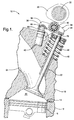
- FIG. 1 is a partial, sectional view of a rocker arm assembly in an overhead cam internal combustion engine;
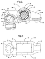
- FIG. 2 is an enlarged sectional side view of the rocker arm of FIG.1; and
- FIG. 3 is an enlarged bottom view of the rocker arm of FIG. 2.
-
- Referring to FIG. 1, there is shown a portion of an overhead camshaft internal combustion engine, designated generally as 10. The
engine 10 includes anengine cylinder block 12 with a plurality ofengine cylinders 14. Anengine piston 16 is disposed within eachcylinder 14 for reciprocal movement. Anengine cylinder head 18 is mounted on thecylinder block 12 and cooperates with eachpiston 16 to define acombustion chamber 20 therebetween. - Each
cylinder 14 has anintake valve 22 to supply air, and fuel in some applications, to thecombustion chamber 20 from anintake passage 24, and an exhaust valve, not shown, to exhaust the combustion gases though an exhaust passage, not shown. Theintake valve 22 is seated in the end of theintake passage 24 which adjoins thecylinder 14. - Valve actuation will be discussed with reference to the
intake valve 22. Acam 30, disposed on acamshaft 32, actuates thevalve 22 via arocker arm assembly 34. In the end-pivot configuration shown, arocker arm 36 pivots at afirst end 38 on ahydraulic lash adjuster 40 that is assembled in thecylinder head 18. Intermediate of therocker arm 36, the arm contacts thecam 30 directly through aroller cam follower 42. At asecond end 44, therocker arm 36 actuates avalve stem 46 to open thevalve 22. Avalve return spring 48 acts to close thevalve 22. Other rocker arm configurations may be used such as a center-pivot configuration. - The
rocker arm assembly 34 is illustrated in greater detail in FIGS. 2 and 3. Therocker arm 36 has a generally U-shaped configuration with abottom wall 50 and twoside walls side walls axle opening 56 to support a transversely extendingroller axle 58 upon whichroller 42 is mounted for rolling contact withcam 30. Needle-type bearings 60 are disposed between theroller 42 andaxle 58. As shown in FIG. 3, thebottom wall 50 includes a centrally-locatedrectangular opening 54 to provide clearance for rotation ofroller 42. - At the
first end 38 of therocker arm 36, there is aspherical socket 62 in thebottom wall 50 operable to receive the upperrounded end 63 of thehydraulic lash adjuster 40. Thedeepest portion 74 of thesocket 62 includes arelief region 64 which provides a gap to allow oil to be expelled through abore 66 in the upperrounded end 63 of thelash adjuster 40 to lubricate the interface between the lash adjuster and the rocker arm socket. An oil reservoir 67 is created between theupper end 63 of thelash adjuster 40 and therelief region 64 of thesocket 62 as the oil is expelled from the lash adjuster. At thesecond end 44 of therocker arm 36, thebottom wall 50 includes a stepped radiusedpallet 68 which interfaces with the top of thevalve stem 46. - To provide additional oil lubrication to the
roller 42,roller bearings 60, and thepallet 68 for thevalve stem 46, anoiling channel 70 is provided along therocker arm 36, which taps into the oil reservoir 67 and channels oil to other portions of the valve train. Thechannel 70 is defined by its two ends, asupply end 72 and adistribution end 73. Thesupply end 72 intersects the oil reservoir 67 defined between thesocket 62 and theupper end 63 of the hydraulic lash adjuster. Thedistribution end 73 intersects therectangular opening 54, provided for theroller 42. Therefore thechannel 70 extends from thesupply end 72, inboard towards theroller 42 and along a portion of thebottom wall 50, to thedistribution end 73. Thechannel 70 provides a path for oil to be redistributed from the oil reservoir 67 to provide further valve train lubrication. Thechannel 70 may be formed as part of therocker arm 36 during stamping, casting, or metal injection molding, or may be manufactured during secondary machining operations. The dimension of thechannel 70 is such that excessive amounts of oil are not channeled away from thelash adjuster 40 so as to not adversely affect system oil pressure. - During operation, oil is delivered to the hydraulic lash adjuster 40 through an
oil passage 76, FIG. 1, in thecylinder head 18. Excess oil is expelled through thebore 66 in theupper end 63 of theadjuster 40, filling the oil reservoir 67. By capillary action and slight pressure, the oil flows in thesupply end 72 of the intersectingoiling channel 70 and therethrough. The rapid motion of therocker arm 36 flings oil from thedistribution end 73 of thechannel 70 onto theroller 42 and to thepallet 68 thereby lubricating thebearing 60 and the interface to thevalve stem 46. Since the oil is sprayed from the underside of the rocker arm, the oil provides lubrication of the rocker arm-to-valve stem interface that may not otherwise be possible if the oil was sprayed from the top side of the rocker arm. - The foregoing description of the preferred embodiment of the invention has been presented for the purpose of illustration and description. It is not intended to be exhaustive, nor is it intended to limit the invention to the precise form disclosed. It will be apparent to those skilled in the art that the disclosed embodiment may be modified in light of the above teachings. The embodiment was chosen to provide an illustration of the principles of the invention and its practical application to thereby enable one of ordinary skill in the art to utilize the invention in various embodiments and with various modifications as are suited to the particular use contemplated. Therefore, the foregoing description is to be considered exemplary, rather than limiting, and the true scope of the invention is that described in the following claims.
Claims (5)
- A rocker arm assembly (34) comprising a rocker arm (36) having U-shaped configuration comprising a bottom wall (50) and two side walls (52, 53) depending upwardly therefrom, said side walls each having a central axle opening (56) to support a transversely extending roller axle (58), a roller (42) for rolling against a cam and rotatably supported on said roller axle through a roller bearing (60), said bottom wall having a centrally located opening (54) providing clearance for rotation of said roller, a spherical socket (62) at a first end of said rocker arm to interface with an upper rounded end of a hydraulic lash adjuster, and a channel (70) provided along said bottom wall extending from said spherical socket, towards said roller, to terminate at said centrally located opening for channeling oil expelled from said hydraulic lash adjuster, wherein reciprocation of said rocker arm flings oil from said channel to said roller and roller bearing for lubrication.
- A rocker arm assembly, as defined in claim 1, further comprising a relief region (64) in said spherical socket of said rocker arm to define an oil reservoir (67) between said upper rounded end of said hydraulic lash adjuster and said relief region.
- A rocker arm assembly, as defined in claim 2, wherein said channel intersects said oil reservoir, channeling oil from said oil reservoir to a distribution end (73) of said channel intersecting said centrally located opening of said bottom wall of said rocker arm.
- A rocker arm assembly, as defined in claim 1, further comprising a pallet (68) in said bottom wall at a second end of said rocker arm to interface a valve stem for valve actuation wherein reciprocation of said rocker arm flings oil from said channel to said pallet for lubrication.
- A rocker arm assembly, as defined in claim 4, wherein said pallet is a stepped and radiused surface.
Applications Claiming Priority (2)
| Application Number | Priority Date | Filing Date | Title |
|---|---|---|---|
| US298390 | 1981-09-01 | ||
| US09/298,390 US5979383A (en) | 1999-04-23 | 1999-04-23 | Rocker arm assembly lubrication |
Publications (3)
| Publication Number | Publication Date |
|---|---|
| EP1046791A2 true EP1046791A2 (en) | 2000-10-25 |
| EP1046791A3 EP1046791A3 (en) | 2002-08-21 |
| EP1046791B1 EP1046791B1 (en) | 2004-03-24 |
Family
ID=23150294
Family Applications (1)
| Application Number | Title | Priority Date | Filing Date |
|---|---|---|---|
| EP00201231A Expired - Lifetime EP1046791B1 (en) | 1999-04-23 | 2000-04-04 | Rocker arm assembly lubrication |
Country Status (4)
| Country | Link |
|---|---|
| US (1) | US5979383A (en) |
| EP (1) | EP1046791B1 (en) |
| BR (1) | BR0001665A (en) |
| DE (1) | DE60009191T2 (en) |
Cited By (1)
| Publication number | Priority date | Publication date | Assignee | Title |
|---|---|---|---|---|
| CN110203377A (en) * | 2019-05-21 | 2019-09-06 | 成都飞机工业(集团)有限责任公司 | A kind of unmanned plane brake oil liquid exempts to be vented filling apparatus and method |
Families Citing this family (20)
| Publication number | Priority date | Publication date | Assignee | Title |
|---|---|---|---|---|
| DE19811658B4 (en) * | 1998-03-18 | 2006-01-26 | Ina-Schaeffler Kg | Pivoting cam follower of a valve train of an internal combustion engine |
| US6484682B2 (en) | 2000-01-26 | 2002-11-26 | International Engine Intellectual Property Company, L.L.C. | Rocker arm assembly |
| ITTO20010133A1 (en) * | 2001-02-15 | 2002-08-16 | Eaton Automotive S R L | VALVE FOR INTERNAL COMBUSTION ENGINE VALVE TRAINS. |
| US7438477B2 (en) * | 2001-11-29 | 2008-10-21 | Ntn Corporation | Bearing part, heat treatment method thereof, and rolling bearing |
| EP1411142B1 (en) * | 2002-10-17 | 2006-03-08 | Ntn Corporation | Full-type rolling bearing and roller cam follower for engine |
| JP4718781B2 (en) * | 2003-02-28 | 2011-07-06 | Ntn株式会社 | Transmission components and tapered roller bearings |
| US7334943B2 (en) * | 2003-02-28 | 2008-02-26 | Ntn Corporation | Differential support structure, differential's component, method of manufacturing differential support structure, and method of manufacturing differential's component |
| JP2004301321A (en) | 2003-03-14 | 2004-10-28 | Ntn Corp | Bearing for alternator and bearing for pulley |
| JP2004293632A (en) * | 2003-03-26 | 2004-10-21 | Ntn Corp | Rolling bearing |
| JP4152283B2 (en) * | 2003-08-29 | 2008-09-17 | Ntn株式会社 | Heat treatment method for bearing parts |
| US7594762B2 (en) | 2004-01-09 | 2009-09-29 | Ntn Corporation | Thrust needle roller bearing, support structure receiving thrust load of compressor for car air-conditioner, support structure receiving thrust load of automatic transmission, support structure for continuously variable transmission, and support structure receivin |
| JP4540351B2 (en) * | 2004-01-15 | 2010-09-08 | Ntn株式会社 | Steel heat treatment method and bearing part manufacturing method |
| DE102004028221A1 (en) * | 2004-06-09 | 2005-12-29 | Ina-Schaeffler Kg | Highly stressed engine component |
| DE102005017409A1 (en) * | 2005-04-15 | 2006-10-19 | Schaeffler Kg | Outer part of a switchable tappet |
| JP2007046717A (en) | 2005-08-10 | 2007-02-22 | Ntn Corp | Rolling-contact shaft with joint claw |
| JP5137627B2 (en) * | 2008-03-07 | 2013-02-06 | 株式会社オティックス | Rocker arm unit and method of assembling the rocker arm unit |
| US8925809B2 (en) * | 2008-10-20 | 2015-01-06 | Codman Neuro Sciences Sarl | Key-card access system for providing selective access to medical equipment |
| US8689750B2 (en) | 2012-02-14 | 2014-04-08 | Eaton Corporation | Camshaft phasing device |
| JP7135817B2 (en) * | 2018-12-11 | 2022-09-13 | トヨタ自動車株式会社 | cylinder head |
| CN114313002B (en) * | 2022-01-24 | 2023-04-14 | 象山申达轿车配件有限公司 | Automobile rocker arm assembly with low friction resistance |
Family Cites Families (13)
| Publication number | Priority date | Publication date | Assignee | Title |
|---|---|---|---|---|
| US3289657A (en) * | 1964-05-25 | 1966-12-06 | Jr John R Winter | Valve actuating mechanism |
| US3855981A (en) * | 1973-05-15 | 1974-12-24 | Ford Motor Co | Rocker arm |
| US4624223A (en) * | 1980-03-27 | 1986-11-25 | Toledo Stamping & Manufacturing Company | Rocker arm and method of making same |
| US4589383A (en) * | 1983-06-09 | 1986-05-20 | Automotive Engine Associates | Squeeze film rocker tip |
| US4961407A (en) * | 1989-04-24 | 1990-10-09 | Competition Cams, Inc. | Rocker arm with a cost push rod seat |
| US4979475A (en) * | 1990-05-25 | 1990-12-25 | Henley Manufacturing Holding Company, Inc. | Rocker arm with rounded channel to engage a valve stem with semi-spherical end |
| US5016582A (en) * | 1990-10-12 | 1991-05-21 | Henley Manufacturing Holding Company, Inc. | Rocker arm |
| JPH04330310A (en) * | 1991-01-31 | 1992-11-18 | Suzuki Motor Corp | Lubrication of valve system for engine |
| DE4234868C2 (en) * | 1992-10-16 | 1999-10-28 | Schaeffler Waelzlager Ohg | Process for the production of a rocker arm or rocker arm |
| US5566652A (en) * | 1995-10-06 | 1996-10-22 | Eaton Corporation | Light weight cam follower |
| US5584267A (en) * | 1995-12-20 | 1996-12-17 | Eaton Corporation | Latchable rocker arm mounting |
| US5671707A (en) * | 1996-02-28 | 1997-09-30 | Cummins Engine Company, Inc. | Rocker level oil shroud |
| DE19624413A1 (en) * | 1996-06-19 | 1998-01-02 | Schaeffler Waelzlager Kg | Tip or drag lever lubrication method |
-
1999
- 1999-04-23 US US09/298,390 patent/US5979383A/en not_active Expired - Fee Related
-
2000
- 2000-04-04 EP EP00201231A patent/EP1046791B1/en not_active Expired - Lifetime
- 2000-04-04 DE DE60009191T patent/DE60009191T2/en not_active Expired - Fee Related
- 2000-04-20 BR BR0001665-9A patent/BR0001665A/en not_active IP Right Cessation
Non-Patent Citations (1)
| Title |
|---|
| None |
Cited By (1)
| Publication number | Priority date | Publication date | Assignee | Title |
|---|---|---|---|---|
| CN110203377A (en) * | 2019-05-21 | 2019-09-06 | 成都飞机工业(集团)有限责任公司 | A kind of unmanned plane brake oil liquid exempts to be vented filling apparatus and method |
Also Published As
| Publication number | Publication date |
|---|---|
| EP1046791A3 (en) | 2002-08-21 |
| DE60009191T2 (en) | 2004-08-12 |
| DE60009191D1 (en) | 2004-04-29 |
| US5979383A (en) | 1999-11-09 |
| BR0001665A (en) | 2000-10-31 |
| EP1046791B1 (en) | 2004-03-24 |
Similar Documents
| Publication | Publication Date | Title |
|---|---|---|
| US5979383A (en) | Rocker arm assembly lubrication | |
| CA1329524C (en) | Rocker arm with cam-contacting roller | |
| EP0785340B1 (en) | A rocker arm assembly for an internal combustion engine | |
| US4825717A (en) | Rocker arm of the cam-follower type with ribs | |
| US5016582A (en) | Rocker arm | |
| EP0608925A1 (en) | Compact valve-lifters | |
| US5566652A (en) | Light weight cam follower | |
| CA1233714A (en) | Integral rocker arm hydraulic lifter and bearing assembly | |
| JPH06317111A (en) | Roller valve lifter | |
| CN106555629B (en) | Valve actuation system | |
| US5063889A (en) | Rocker arm with lubrication provisions | |
| EP0128748A2 (en) | Squeeze film rocker tip | |
| US5372097A (en) | Self-lubricating cam follower | |
| EP0851100A1 (en) | Hydraulic lash adjuster arrangement | |
| GB2447112A (en) | I.c. engine cam-in-block valve train with valves operated by individual pushrods actuated by a common cam follower | |
| EP0091096B1 (en) | Valve operating system of internal combustion engine | |
| EP1288446B1 (en) | A tappet for an internal combustion engine | |
| JPH0263082B2 (en) | ||
| US5325826A (en) | Journal bearing oil diverter | |
| US8096274B2 (en) | Rocker arm arrangement with a bearing shell provided with grooves | |
| EP0377829B2 (en) | Camshaft lubrication system for an internal-combustion engine | |
| US5749341A (en) | Valve lifter for internal combustion engines | |
| JP2580163Y2 (en) | Lubrication structure of valve gear | |
| EP0857857B1 (en) | Rocker arm assembly | |
| JPH10288011A (en) | Crosshead lubrication structure |
Legal Events
| Date | Code | Title | Description |
|---|---|---|---|
| PUAI | Public reference made under article 153(3) epc to a published international application that has entered the european phase |
Free format text: ORIGINAL CODE: 0009012 |
|
| AK | Designated contracting states |
Kind code of ref document: A2 Designated state(s): AT BE CH CY DE DK ES FI FR GB GR IE IT LI LU MC NL PT SE |
|
| AX | Request for extension of the european patent |
Free format text: AL;LT;LV;MK;RO;SI |
|
| PUAL | Search report despatched |
Free format text: ORIGINAL CODE: 0009013 |
|
| AK | Designated contracting states |
Kind code of ref document: A3 Designated state(s): AT BE CH CY DE DK ES FI FR GB GR IE IT LI LU MC NL PT SE |
|
| AX | Request for extension of the european patent |
Free format text: AL;LT;LV;MK;RO;SI |
|
| 17P | Request for examination filed |
Effective date: 20030221 |
|
| AKX | Designation fees paid |
Designated state(s): DE FR GB IT |
|
| GRAP | Despatch of communication of intention to grant a patent |
Free format text: ORIGINAL CODE: EPIDOSNIGR1 |
|
| RIN1 | Information on inventor provided before grant (corrected) |
Inventor name: GREENE, CYNTHIA Inventor name: FAVILLE, JOYCE |
|
| GRAS | Grant fee paid |
Free format text: ORIGINAL CODE: EPIDOSNIGR3 |
|
| GRAA | (expected) grant |
Free format text: ORIGINAL CODE: 0009210 |
|
| AK | Designated contracting states |
Kind code of ref document: B1 Designated state(s): DE FR GB IT |
|
| PG25 | Lapsed in a contracting state [announced via postgrant information from national office to epo] |
Ref country code: FR Free format text: LAPSE BECAUSE OF FAILURE TO SUBMIT A TRANSLATION OF THE DESCRIPTION OR TO PAY THE FEE WITHIN THE PRESCRIBED TIME-LIMIT Effective date: 20040324 Ref country code: IT Free format text: LAPSE BECAUSE OF FAILURE TO SUBMIT A TRANSLATION OF THE DESCRIPTION OR TO PAY THE FEE WITHIN THE PRE;WARNING: LAPSES OF ITALIAN PATENTS WITH EFFECTIVE DATE BEFORE 2007 MAY HAVE OCCURRED AT ANY TIME BEFORE 2007. THE CORRECT EFFECTIVE DATE MAY BE DIFFERENT FROM THE ONE RECORDED.SCRIBED TIME-LIMIT Effective date: 20040324 |
|
| REG | Reference to a national code |
Ref country code: GB Ref legal event code: FG4D |
|
| REG | Reference to a national code |
Ref country code: IE Ref legal event code: FG4D |
|
| REF | Corresponds to: |
Ref document number: 60009191 Country of ref document: DE Date of ref document: 20040429 Kind code of ref document: P |
|
| PG25 | Lapsed in a contracting state [announced via postgrant information from national office to epo] |
Ref country code: GB Free format text: LAPSE BECAUSE OF NON-PAYMENT OF DUE FEES Effective date: 20040624 |
|
| REG | Reference to a national code |
Ref country code: IE Ref legal event code: MM4A |
|
| PLBE | No opposition filed within time limit |
Free format text: ORIGINAL CODE: 0009261 |
|
| STAA | Information on the status of an ep patent application or granted ep patent |
Free format text: STATUS: NO OPPOSITION FILED WITHIN TIME LIMIT |
|
| GBPC | Gb: european patent ceased through non-payment of renewal fee |
Effective date: 20040624 |
|
| EN | Fr: translation not filed | ||
| 26N | No opposition filed |
Effective date: 20041228 |
|
| PGFP | Annual fee paid to national office [announced via postgrant information from national office to epo] |
Ref country code: DE Payment date: 20080411 Year of fee payment: 9 |
|
| PG25 | Lapsed in a contracting state [announced via postgrant information from national office to epo] |
Ref country code: DE Free format text: LAPSE BECAUSE OF NON-PAYMENT OF DUE FEES Effective date: 20091103 |