EP1046782A2 - Self contained downhole sensor and method of placing and interrogating same - Google Patents
Self contained downhole sensor and method of placing and interrogating same Download PDFInfo
- Publication number
- EP1046782A2 EP1046782A2 EP00303300A EP00303300A EP1046782A2 EP 1046782 A2 EP1046782 A2 EP 1046782A2 EP 00303300 A EP00303300 A EP 00303300A EP 00303300 A EP00303300 A EP 00303300A EP 1046782 A2 EP1046782 A2 EP 1046782A2
- Authority
- EP
- European Patent Office
- Prior art keywords
- well
- contained
- casing
- parameter
- housing
- Prior art date
- Legal status (The legal status is an assumption and is not a legal conclusion. Google has not performed a legal analysis and makes no representation as to the accuracy of the status listed.)
- Withdrawn
Links
Images


Classifications
-
- E—FIXED CONSTRUCTIONS
- E21—EARTH OR ROCK DRILLING; MINING
- E21B—EARTH OR ROCK DRILLING; OBTAINING OIL, GAS, WATER, SOLUBLE OR MELTABLE MATERIALS OR A SLURRY OF MINERALS FROM WELLS
- E21B41/00—Equipment or details not covered by groups E21B15/00 - E21B40/00
- E21B41/0085—Adaptations of electric power generating means for use in boreholes
-
- E—FIXED CONSTRUCTIONS
- E21—EARTH OR ROCK DRILLING; MINING
- E21B—EARTH OR ROCK DRILLING; OBTAINING OIL, GAS, WATER, SOLUBLE OR MELTABLE MATERIALS OR A SLURRY OF MINERALS FROM WELLS
- E21B47/00—Survey of boreholes or wells
- E21B47/01—Devices for supporting measuring instruments on drill bits, pipes, rods or wirelines; Protecting measuring instruments in boreholes against heat, shock, pressure or the like
-
- E—FIXED CONSTRUCTIONS
- E21—EARTH OR ROCK DRILLING; MINING
- E21B—EARTH OR ROCK DRILLING; OBTAINING OIL, GAS, WATER, SOLUBLE OR MELTABLE MATERIALS OR A SLURRY OF MINERALS FROM WELLS
- E21B47/00—Survey of boreholes or wells
- E21B47/12—Means for transmitting measuring-signals or control signals from the well to the surface, or from the surface to the well, e.g. for logging while drilling
- E21B47/138—Devices entrained in the flow of well-bore fluid for transmitting data, control or actuation signals
-
- E—FIXED CONSTRUCTIONS
- E21—EARTH OR ROCK DRILLING; MINING
- E21B—EARTH OR ROCK DRILLING; OBTAINING OIL, GAS, WATER, SOLUBLE OR MELTABLE MATERIALS OR A SLURRY OF MINERALS FROM WELLS
- E21B47/00—Survey of boreholes or wells
- E21B47/26—Storing data down-hole, e.g. in a memory or on a record carrier
Definitions
- the present invention is directed, in general, to subterranean exploration and production and, more specifically, to a system and method for placing multiple sensors, especially self-contained sensors, in a subterranean well and obtaining subterranean parameters from the sensors.
- the oil industry today relies on many technologies in its quest for the location of new reserves and to optimize oil and gas production from individual wells. Perhaps the most general of these technologies is a knowledge of the geology of a region of interest.
- the geologist uses a collection of tools to estimate whether a region may have the potential for holding subterranean accumulations of hydrocarbons. Many of these tools are employed at the surface to predict what situations may be present in the subsurface.
- the more detailed knowledge of the formation that is available to the geophysicist the better decisions that can be made regarding production.
- Preliminary geologic information about the subterranean structure of a potential well site may be obtained through seismic prospecting.
- An acoustic energy source is applied at the surface above a region to be explored. As the energy wavefront propagates downward, it is partially reflected by each subterranean layer and collected by a surface sensor array, thereby producing a time dependent recording. This recording is then analyzed to develop an estimation of the subsurface situation.
- a geophysicist then studies these geophysical maps to identify significant events that may determine viable prospecting areas for drilling a well.
- Properly managing the production of a given well is important in obtaining optimum long-term production.
- a given well may be capable of a greater initial flow rate, that same higher initial production may be counter to the goal of maximum overall production.
- High flow rates may cause structural changes to the producing formation that prevents recovering the maximum amount of resident hydrocarbon.
- direct readings are available only within the confines of the well and produce a two-dimensional view of the formation.
- a multi-parameter sensing system that: (a) overcomes the damage-prone shortcomings of the umbilical system, (b) may be readily placed in a well bore, as deep into the geologic formation as possible, (c) can provide a quasi three-dimensional picture of the well, and (d) can be interrogated upon command.
- the present invention provides a self-contained sensor module for use in a subterranean well that has a well transmitter or a well receiver associated therewith.
- the sensor module comprises a housing, a signal receiver, a parameter sensor, an electronic control assembly, and a parameter transmitter.
- the receiver, sensor, control assembly and transmitter are all contained within the housing.
- the housing has a size that allows the module to be positioned within a formation about the well or in an annulus between a casing positioned within the well and an outer diameter of the well.
- the signal receiver is configured to receive a signal from the well transmitter, while the parameter sensor is configured to sense a physical parameter of an environment surrounding the sensor module within the well.
- the electronic control assembly is coupled to both the signal receiver and the parameter sensor, and is configured to convert the physical parameter to a data signal.
- the parameter transmitter is coupled to the electronic control assembly and is configured to transmit the data signal to the well receiver.
- the sensor module further includes an energy storage device coupled to the signal receiver and the electronic control assembly.
- the energy storage device may be various types of power sources, such as a battery, a capacitor, or a nuclear fuel cell.
- the sensor module also includes an energy converter that is coupled to the signal receiver. The energy converter converts the signal to electrical energy for storage in the energy storage device.
- the signal receiver may be an acoustic vibration sensor, a piezoelectric element or a triaxial voice coil.
- the sensor module has a size that is less than an inner diameter of an annular bottom plug in the casing.
- the signal receiver and the parameter transmitter are a transceiver.
- the physical parameter to be measured may be: temperature, pressure, acceleration, resistivity, porosity, or flow rate.
- the signal may be electromagnetic, seismic, or acoustic in nature.
- the housing may also be a variety of shapes, such as prolate, spherical, or oblate spherical.
- the housing in one embodiment, may be constructed of a semicompliant material.
- a self-contained sensor module for use in a subterranean well bore having a well transmitter or a well receiver associated therewith, comprising: a housing having a size that allows said module to be positioned within a formation about said well or between a casing positioned within said well and an outer diameter of said well bore; a signal receiver contained within said housing and configured to receive a signal from said well transmitter; a parameter sensor contained within said housing and configured to sense a physical parameter of an environment surrounding said sensor module within said well; an electronic control assembly contained within said housing, said electronic control assembly coupled to said signal receiver and said parameter sensor and configured to convert said physical parameter to a data signal; and a parameter transmitter contained within said housing, said parameter transmitter coupled to said electronic control assembly and configured to transmit said data signal to said well receiver.
- the sensor module further comprises an energy storage device coupled to said signal receiver and said electronic control assembly, said energy storage device being a battery, a capacitor, or a nuclear fuel cell.
- the sensor module further comprises an energy converter coupled to said signal receiver, said energy converter configured to convert said signal to electrical energy for storage in said energy storage device.
- the signal receiver is an acoustic vibration sensor, a piezoelectric element or a triaxial voice coil.
- said size is less than an inner diameter of an annular bottom plug of said casing, said annular bottom plug having an axial aperture therethrough and a rupturable membrane disposed across said axial aperture.
- said signal receiver and said parameter transmitter are a transceiver.
- said physical parameter is temperature, pressure, acceleration, resistivity, porosity, gamma radiation, magnetic field or flow rate.
- said signal is electromagnetic, radio frequency, seismic or acoustic.
- the shape of said housing is prolate, spherical or oblate spherical.
- the housing may be constructed of a semicompliant material.
- a system for deploying self-contained sensor modules into a production formation of a subterranean well comprising: a casing disposed within said well and having perforations formed therein; a hydraulic system capable of pumping a pressurized fluid through said casing and perforations; a packer system capable of isolating said production formation to allow a flow of said pressurized fluid into said production formation; and a plurality of self-contained sensor modules each having an overall dimension that allows each of said self-contained sensor modules to pass through said perforations and into said production formation.
- Each of said self-contained sensor modules may have any combination of the features of the self-contained sensor modules described above
- a method for deploying self contained sensor modules into a production zone of a subterranean well bore comprising the steps of: installing a casing in said subterranean well bore; perforating said casing adjacent a production zone to cause a plurality of perforations; isolating said production zone with a packer system; pumping a pressurized fluid into said casing; dispensing self-contained sensor modules into said pressurized fluid; and forcing a plurality of said self-contained sensor modules into said production zone with said pressurized fluid.
- the forcing includes forcing a self-contained sensor module having any combination of the features of the self-contained sensor module described above.
- a system for deploying self-contained sensor modules into a well annulus of a subterranean well comprising: a casing disposed within said subterranean well; an annular bottom plug within said casing having a coaxial aperture therethrough and a rupturable membrane disposed across said coaxial aperture; a slurry dispenser coupleable to said casing and configured to dispense a cement slurry into said casing; a module dispenser coupleable to said slurry dispenser and configured to dispense a plurality of self-contained sensor modules into said cement slurry; a top plug within said casing and above said cement slurry, said top plug configured to seal said cement slurry from a drilling fluid; and a hydraulic system coupleable to said casing and configured to pump said drilling fluid under a pressure, said pressure sufficient to rupture said rupturable membrane and force at least some of said drilling fluid and at least some of said sensor modules into said well annulus.
- the self-contained sensor module may have any combination of the features of the self-contained sensor modules described above
- a method for deploying self-contained sensor modules into a well annulus of a subterranean well having a well bore comprising the steps of installing a casing in said subterranean well, thereby creating said well annulus between an outer surface of said casing and an inner surface of said well bore; installing an annular plug in a bottom of said casing, said annular plug having a coaxial aperture therethrough and a rupturable membrane disposed across said coaxial aperture; pumping a cement slurry into said casing; dispensing self-contained sensor modules into said cement slurry; installing a top plug within said casing and above said cement slurry, said top plug configured to slidably seal said cement slurry from a drilling fluid; pumping said drilling fluid under a pressure, said pressure forcing said top plug to slide downhole within said casing and force said slurry against said rupturable membrane, thereby rupturing said rupturable membrane; and forcing said cement slurry and a
- the forcing includes forcing a self-contained sensor module having any combination of the features of the self-contained sensor module described above.
- a subterranean well comprising: a well bore having a casing therein, said casing creating a well annulus between an outer surface of said casing and an inner surface of said well bore; a production zone about said well; and a plurality of self-contained sensor modules wherein said self-contained sensor modules are positioned within said well annulus or said production zone, said self-contained sensor modules including: a housing having a size that allows said module to be positioned within a formation about said subterranean well or between a casing positioned within said subterranean well and an outer diameter of said well bore; a signal receiver contained within said housing and configured to receive a signal from said well transmitter; a parameter sensor contained within said housing and configured to sense a physical parameter of an environment surrounding said sensor module within said subterranean well; an electronic control assembly contained within said housing, said electronic control assembly coupled to said signal receiver and said parameter sensor and configured to convert said physical parameter to a data signal; and a parameter transmitter
- said self-contained sensor module further comprises any combination of the features of the self-contained sensor module described above.
- At least some of said plurality of self-contained sensor modules are distributed throughout said well annulus.
- At least some of said plurality of self-contained sensor modules are embedded in said production zone.
- a method of operating a sensor system disposed within a subterranean well comprising: positioning a self-contained sensor module into said subterranean well, said self-contained sensor module including: a housing having a size that allows said module to be positioned between a casing within said subterranean well and an outer diameter of said subterranean well; a signal receiver contained within said housing and configured to receive a signal from a well transmitter; a parameter sensor contained within said housing and configured to sense a physical parameter of an environment surrounding said sensor module within said subterranean well; an electronic control assembly contained within said housing, said electronic control assembly coupled to said signal receiver and said parameter sensor and configured to convert said physical parameter to a data signal; and a parameter transmitter contained within said housing, said parameter transmitter coupled to said electronic control assembly and configured to transmit said data signal to a receiver associated with said well; exciting said signal receiver; sensing a physical parameter of an environment surrounding said sensor module; converting said physical parameter to a data signal;
- the positioning includes positioning said modules in a production formation.
- the positioning includes positioning said modules in an annulus between said casing and said outer diameter of said subterranean well.
- the exciting includes exciting with a transmitter on a wireline tool.
- the exciting includes exciting with a seismic wave.
- the exciting includes interrogating said module to cause said parameter transmitter to transmit said data signal.
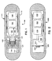
- a self-contained sensor module 100 comprises a housing 110, and a signal receiver 120, an energy storage device 130, a parameter sensor 140, an electronic control assembly 150, and a parameter transmitter 160 contained within the housing 110.
- the signal receiver 120 and parameter transmitter 160 may be a transceiver.
- the housing 110 may be constructed of any suitable material, e.g ., aluminum, steel, etc ., that can withstand the rigors of its environment; however in a particular embodiment, the housing may be, at least partly, of a semicompliant material, such as a resilient plastic.
- the housing 110 preferably has a size that enables the module 100 to be positioned in a producing formation or in an annulus between a well casing and a well bore to be described below. While the shape of the housing 110 illustrated may be prolate, other embodiments of spherical or oblate spherical shapes are also well suited to placing the housing 110 in a desired location within a subterranean well. However, any shape that will accommodate necessary system electronics and facilitate placing the module 100 where desired in the well may be used as well.
- the signal receiver 120 is an acoustic vibration sensor that may also be termed an energy converter.
- the acoustic vibration sensor 120 comprises a spring 121, a floating bushing 122, bearings 123, a permanent magnet 124, and electrical coils 125. Under the influence of an acoustic signal, which is discussed below, the floating bushing 122 and permanent magnet 124 vibrate setting up a current in electrical coils 125.
- the current generated is routed to the energy storage device 130, which may be a battery or a capacitor.
- the energy storage device 130 may be a nuclear fuel cell that does not require charging from the signal receiver 120.
- the signal receiver 120 may be coupled directly to the electronic control assembly 150.
- the energy storage device 130 is a battery.
- the electronic control assembly 150 is electrically coupled between the energy storage device 130 and the parameter sensor 140.
- the parameter sensor 140 is configured to sense one or more of the following physical parameters: temperature, pressure, acceleration, resistivity, porosity, chemical properties, cement strain, and flow rate.
- a strain gauge 141 or other sensor, is coupled to the parameter sensor 140 in order to sense pressure exerted on the compliant casing 110.
- Other methods of collecting pressure such as piezoelectric elements, etc ., may also by used.
- sensors 141 located entirely within the housing 110 sensors may also by mounted on or extend to an exterior surface 111 of the housing while remaining within the broadest scope of the present invention.
- a signal receiver 220 of a self-contained sensor module 200 is a piezoelectric element 221 and a mass 222.
- the mass 222 and piezoelectric element 221 displace as the result of an acoustic signal, setting up a current in the piezoelectric element 221 that is routed to the energy storage device 130.
- Self-contained sensor module 200 further comprises an energy storage device 230, a parameter sensor 240, an electronic control assembly 250, and a parameter transmitter 260 that are analogous to their counterparts of FIGURE 1 and are well known individual electronic components.
- a signal receiver 320 of a self-contained sensor module 300 is a triaxial voice coil 321 consisting of voice coils 321a, 321b, and 321c.
- signals generated within the voice coils 321a, 321b, and 321c are routed through ac to dc converters 322a, 322b, 322c and summed for an output 323 to an energy storage device 330 or, alternatively, directly to an electronic control assembly 350.
- the functions of parameter sensor 340, electronic control assembly 350, and parameter transmitter 360 are analogous to their counterparts of FIGURE 1.
- a subterranean well 400 comprises a well bore 410, a casing 420 having perforations 425 formed therein, a production zone 430, a conventional hydraulic system 440, a conventional packer system 450, a module dispenser 460, and a plurality of self-contained sensor modules 470.
- the well 400 has been packed off with the packer system 450 comprising a well packer 451 between the casing 420 and the well bore 410, and a casing packer 452 within the casing 420.
- Hydraulic system 440 at least temporarily coupled to a surface location 421 of the well casing 420, pumps a fluid 441, typically a drilling fluid, into the casing 420 as the module dispenser 460 distributes the plurality of self-contained sensor modules 470 into the fluid 441.
- FIGURE 4B illustrated is a sectional view of the subterranean well of FIGURE 4A with a plurality of the self-contained sensor modules of FIGURE 1 placed in the formation.
- the fluid 441 is prevented from passing beyond casing packer 452; therefore, the fluid 441 is routed under pressure through perforations 425 into a well annulus 411 between the well casing 420 and the well bore 410.
- the module 470 is of such a size that it may pass through the perforations with the fluid 441 and, thereby enable at least some of the plurality of self-contained sensor modules 470 to be positioned in the producing formation 430.
- the prolate, spherical, or oblate spherical shape of the modules 470 facilitates placement of the modules in the formation 430.
- a subterranean well 500 comprises a well bore 510, a casing 520, a well annulus 525, a production zone 530, a hydraulic system 540, an annular bottom plug 550, a module dispenser 560, a plurality of self-contained sensor modules 570, a cement slurry 580, and a top plug 590.
- the annular bottom plug 550 has an axial aperture 551 therethrough and a rupturable membrane 552 across the axial aperture 551.
- a volume of cement slurry 580 sufficient to fill at least a portion of the well annulus 525 is pumped into the well casing 520.
- the module dispenser 560 distributes the plurality of self-contained sensor modules 570 into the cement slurry 580.
- the top plug 590 is installed in the casing 520. Under pressure from the hydraulic system 540, a drilling fluid 545 forces the top plug 590 downward and the cement slurry 580 ruptures the rupturable membrane 552.
- FIGURE 5B illustrated is a sectional view of the subterranean well of FIGURE 5A with the plurality of self-contained sensor modules of FIGURE 1 placed in the well annulus.
- the cement slurry 580 and modules 570 flow under pressure into the well annulus 525.
- the size of the modules 570 is such that the modules 570 may pass through the axial aperture 551 with the cement slurry 580 and enable at least some of the plurality of self-contained sensor modules 570 to be positioned in the well annulus 525.
- the prolate, spherical, or oblate spherical shape of the module 570 facilitates placement of the module in the well annulus 525.
- One who is skilled in the art is familiar with the use of cement slurry to fill a well annulus.
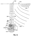
- FIGURE 6 illustrates a sectional view of a portion of the subterranean well of FIGURE 5 with a plurality of self-contained sensor modules 570 distributed in the well annulus 525.
- the sensor module 100 of FIGURE 1 and the sensor modules 570 of FIGURE 5 are identical.
- the other embodiments of FIGURES 2 and 3 may readily be substituted for the sensor module of FIGURE 1.
- a wireline tool 610 has been inserted into the well casing 520 and proximate sensor modules 570.
- the wireline tool 610 comprises a well transmitter 612 that creates a signal 615 configured to be received by the signal receiver 120.
- the signal 615 may be electromagnetic, radio frequency, or acoustic.
- a seismic signal 625 may be created at a surface 630 near the well 500 so as to excite the signal receiver 120.
- One who is skilled in the art is familiar with the creation of seismic waves in subterranean well exploration.
- a single sensor module 671 is shown reacting to the signal 615 while it is understood that other modules would also receive the signal 615.
- the signal 615 may be tuned in a variety of ways to interrogate a particular type of sensor, e.g ., pressure, temperature, etc ., or only those sensors within a specific location of the well by controlling various parameters of the signal 615 and functionality of the sensor module 570, or multiple sensors can be interrogated at once.
- the floating bushing 122 and permanent magnet 124 vibrate, setting up a current in coils 125.
- the generated current is routed to the energy storage device 130 that powers the electronic control assembly 150, the parameter sensor 140, and the parameter transmitter 160.
- the electronic control assembly 150 may be directed by signals 615 or 625 to collect and transmit one or more of the physical parameters previously enumerated.
- the physical parameters sensed by the parameter sensor 140 are converted by the electronic control assembly 150 into a data signal 645 that is transmitted by the parameter transmitter 160.
- the data signal 645 may be collected by a well receiver 614 and processed by a variety of means well understood by one who is skilled in the art. It should also be recognized that the well receiver 614 need not be collocated with the well transmitter 612.
- the illustrated embodiment is of one having sensor modules 570 deployed in the cement slurry 580 of a subterranean well 500.
- modules 570 are also readily applicable to the well 400 of FIGURE 4 wherein the modules 470 are located in the production formation 430. It should be clear to one who is skilled in the art that modules 100, 200, 300, 470, and 570 are interchangeable in application to well configurations 400 or 500, or various combinations thereof.
- a self-contained sensor module 100 that permits placement in a producing formation or in a well annulus.
- a plurality of the sensor modules 100 may be interrogated by a signal from a transmitter on a wireline or other common well tool, or by seismic energy, to collect parameter data associated with the location of the sensor modules 100.
- the modules may be readily located in the well annulus or a producing formation. Local physical parameters may be measured and the parameters transmitted to a collection system for analysis.
- the sensor modules 100 may be located within the well bore at varying elevations and azimuths from the well axis, an approximation to a 360 degree or three dimensional model of the well may be obtained.
- the interrogation signal may be used to transmit energy that the module can convert and store electrically.
- the electrical energy may then be used to power the electronic control assembly, parameter sensor, and parameter transmitter.
Landscapes
- Engineering & Computer Science (AREA)
- Geology (AREA)
- Life Sciences & Earth Sciences (AREA)
- Mining & Mineral Resources (AREA)
- Physics & Mathematics (AREA)
- Environmental & Geological Engineering (AREA)
- Fluid Mechanics (AREA)
- General Life Sciences & Earth Sciences (AREA)
- Geochemistry & Mineralogy (AREA)
- Geophysics (AREA)
- Remote Sensing (AREA)
- Arrangements For Transmission Of Measured Signals (AREA)
- Testing Or Calibration Of Command Recording Devices (AREA)
- Geophysics And Detection Of Objects (AREA)
Abstract
Description
Claims (10)
- A self-contained sensor module for use in a subterranean well bore having a well transmitter or a well receiver associated therewith, comprising: a housing having a size that allows said module to be positioned within a formation about said well or between a casing positioned within said well and an outer diameter of said well bore; a signal receiver contained within said housing and configured to receive a signal from said well transmitter; a parameter sensor contained within said housing and configured to sense a physical parameter of an environment surrounding said sensor module within said well; an electronic control assembly contained within said housing, said electronic control assembly coupled to said signal receiver and said parameter sensor and configured to convert said physical parameter to a data signal; and a parameter transmitter contained within said housing, said parameter transmitter coupled to said electronic control assembly and configured to transmit said data signal to said well receiver.
- A sensor module according to Claim 1, further comprising an energy storage device coupled to said signal receiver and said electronic control assembly, said energy storage device being a battery, a capacitor, or a nuclear fuel cell.
- A system for deploying self-contained sensor modules into a production formation of a subterranean well, comprising: a casing disposed within said well and having perforations formed therein; a hydraulic system capable of pumping a pressurized fluid through said casing and perforations; a packer system capable of isolating said production formation to allow a flow of said pressurized fluid into said production formation; and a plurality of self-contained sensor modules each having an overall dimension that allows each of said self-contained sensor modules to pass through said perforations and into said production formation.
- A system for deploying self-contained sensor modules into a well annulus of a subterranean well, comprising: a casing disposed within said subterranean well; an annular bottom plug within said casing having a coaxial aperture therethrough and a rupturable membrane disposed across said coaxial aperture; a slurry dispenser coupleable to said casing and configured to dispense a cement slurry into said casing; a module dispenser coupleable to said slurry dispenser and configured to dispense a plurality of self-contained sensor modules into said cement slurry; a top plug within said casing and above said cement slurry, said top plug configured to seal said cement slurry from a drilling fluid; and a hydraulic system coupleable to said casing and configured to pump said drilling fluid under a pressure, said pressure sufficient to rupture said rupturable membrane and force at least some of said drilling fluid and at least some of said sensor modules into said well annulus.
- A system according to Claim 3 or 4, wherein the or each self-contained sensor module comprises: a housing having a size that allows said module to be positioned within a formation about said subterranean well or between a casing positioned within said subterranean well and an outer diameter of said subterranean well; a signal receiver contained within said housing and configured to receive a signal from a well transmitter; a parameter sensor contained within said housing and configured to sense a physical parameter of an environment surrounding said sensor module within said subterranean well; an electronic control assembly contained within said housing, said electronic control assembly coupled to said signal receiver and said parameter sensor and configured to convert said physical parameter to a data signal; and a parameter transmitter contained within said housing, said parameter transmitter coupled to said electronic control assembly and configured to transmit said data signal to a receiver associated with said well.
- A method for deploying self-contained sensor modules into a production zone of a subterranean well bore, comprising the steps of: installing a casing in said subterranean well bore; perforating said casing adjacent a production zone to cause a plurality of perforations; isolating said production zone with a packer system; pumping a pressurized fluid into said casing; dispensing self-contained sensor modules into said pressurized fluid; and forcing a plurality of said self-contained sensor modules into said production zone with said pressurized fluid.
- A method for deploying self-contained sensor modules into a well annulus of a subterranean well having a well bore, comprising the steps of installing a casing in said subterranean well, thereby creating said well annulus between an outer surface of said casing and an inner surface of said well bore; installing an annular plug in a bottom of said casing, said annular plug having a coaxial aperture therethrough and a rupturable membrane disposed across said coaxial aperture; pumping a cement slurry into said casing; dispensing self-contained sensor modules into said cement slurry; installing a top plug within said casing and above said cement slurry, said top plug configured to slidably seal said cement slurry from a drilling fluid; pumping said drilling fluid under a pressure, said pressure forcing said top plug to slide downhole within said casing and force said slurry against said rupturable membrane, thereby rupturing said rupturable membrane; and forcing said cement slurry and a plurality of said self-contained sensor modules with said pressure into said well annulus.
- A method according to Claim 6 or 7, wherein forcing includes forcing a self-contained sensor module, comprising: a housing having a size that allows said module to be positioned within a formation about a subterranean well or between a casing positioned within said subterranean well and an outer diameter of said subterranean well; a signal receiver contained within said housing and configured to receive a signal from a well transmitter; a parameter sensor contained within said housing and configured to sense a physical parameter of an environment surrounding said sensor module within said subterranean well; an electronic control assembly contained within said housing, said electronic control assembly coupled to said signal receiver and said parameter sensor and configured to convert said physical parameter to a data signal; and a parameter transmitter contained within said housing, said parameter transmitter coupled to said electronic control assembly and configured to transmit said data signal to a receiver associated with said well.
- A subterranean well, comprising: a well bore having a casing therein, said casing creating a well annulus between an outer surface of said casing and an inner surface of said well bore; a production zone about said well; and a plurality of self-contained sensor modules wherein said self-contained sensor modules are positioned within said well annulus or said production zone, said self-contained sensor modules including: a housing having a size that allows said module to be positioned within a formation about said subterranean well or between a casing positioned within said subterranean well and an outer diameter of said well bore; a signal receiver contained within said housing and configured to receive a signal from said well transmitter; a parameter sensor contained within said housing and configured to sense a physical parameter of an environment surrounding said sensor module within said subterranean well; an electronic control assembly contained within said housing, said electronic control assembly coupled to said signal receiver and said parameter sensor and configured to convert said physical parameter to a data signal; and a parameter transmitter contained within said housing, said parameter transmitter coupled to said electronic control assembly and configured to transmit said data signal to a receiver associated with said well.
- A method of operating a sensor system disposed within a subterranean well, comprising: positioning a self-contained sensor module into said subterranean well, said self-contained sensor module including: a housing having a size that allows said module to be positioned between a casing within said subterranean well and an outer diameter of said subterranean well; a signal receiver contained within said housing and configured to receive a signal from a well transmitter; a parameter sensor contained within said housing and configured to sense a physical parameter of an environment surrounding said sensor module within said subterranean well; an electronic control assembly contained within said housing, said electronic control assembly coupled to said signal receiver and said parameter sensor and configured to convert said physical parameter to a data signal; and a parameter transmitter contained within said housing, said parameter transmitter coupled to said electronic control assembly and configured to transmit said data signal to a receiver associated with said well; exciting said signal receiver; sensing a physical parameter of an environment surrounding said sensor module; converting said physical parameter to a data signal; and transmitting said data signal to a receiver associated with said well.
Applications Claiming Priority (2)
| Application Number | Priority Date | Filing Date | Title |
|---|---|---|---|
| US298725 | 1999-04-23 | ||
| US09/298,725 US6538576B1 (en) | 1999-04-23 | 1999-04-23 | Self-contained downhole sensor and method of placing and interrogating same |
Publications (2)
| Publication Number | Publication Date |
|---|---|
| EP1046782A2 true EP1046782A2 (en) | 2000-10-25 |
| EP1046782A3 EP1046782A3 (en) | 2002-11-20 |
Family
ID=23151776
Family Applications (1)
| Application Number | Title | Priority Date | Filing Date |
|---|---|---|---|
| EP00303300A Withdrawn EP1046782A3 (en) | 1999-04-23 | 2000-04-19 | Self contained downhole sensor and method of placing and interrogating same |
Country Status (5)
| Country | Link |
|---|---|
| US (3) | US6538576B1 (en) |
| EP (1) | EP1046782A3 (en) |
| AU (1) | AU774992B2 (en) |
| CA (1) | CA2305884A1 (en) |
| NO (1) | NO20001966L (en) |
Cited By (3)
| Publication number | Priority date | Publication date | Assignee | Title |
|---|---|---|---|---|
| GB2410088A (en) * | 2004-01-08 | 2005-07-20 | Schlumberger Holdings | Integrated acoustic transducer assembly |
| EP1350309A4 (en) * | 2000-11-07 | 2005-12-21 | Halliburton Energy Serv Inc | Internal power source for downhole detection system |
| EP1903181B1 (en) * | 2006-09-20 | 2012-02-01 | Services Pétroliers Schlumberger | Contact-less sensor cartridge |
Families Citing this family (159)
| Publication number | Priority date | Publication date | Assignee | Title |
|---|---|---|---|---|
| US7040420B2 (en) * | 1994-10-14 | 2006-05-09 | Weatherford/Lamb, Inc. | Methods and apparatus for cementing drill strings in place for one pass drilling and completion of oil and gas wells |
| US7100710B2 (en) | 1994-10-14 | 2006-09-05 | Weatherford/Lamb, Inc. | Methods and apparatus for cementing drill strings in place for one pass drilling and completion of oil and gas wells |
| US6868906B1 (en) | 1994-10-14 | 2005-03-22 | Weatherford/Lamb, Inc. | Closed-loop conveyance systems for well servicing |
| US7147068B2 (en) | 1994-10-14 | 2006-12-12 | Weatherford / Lamb, Inc. | Methods and apparatus for cementing drill strings in place for one pass drilling and completion of oil and gas wells |
| US7036610B1 (en) | 1994-10-14 | 2006-05-02 | Weatherford / Lamb, Inc. | Apparatus and method for completing oil and gas wells |
| US7013997B2 (en) * | 1994-10-14 | 2006-03-21 | Weatherford/Lamb, Inc. | Methods and apparatus for cementing drill strings in place for one pass drilling and completion of oil and gas wells |
| US6857486B2 (en) | 2001-08-19 | 2005-02-22 | Smart Drilling And Completion, Inc. | High power umbilicals for subterranean electric drilling machines and remotely operated vehicles |
| US7228901B2 (en) * | 1994-10-14 | 2007-06-12 | Weatherford/Lamb, Inc. | Method and apparatus for cementing drill strings in place for one pass drilling and completion of oil and gas wells |
| US7108084B2 (en) | 1994-10-14 | 2006-09-19 | Weatherford/Lamb, Inc. | Methods and apparatus for cementing drill strings in place for one pass drilling and completion of oil and gas wells |
| US6693553B1 (en) | 1997-06-02 | 2004-02-17 | Schlumberger Technology Corporation | Reservoir management system and method |
| US6691779B1 (en) | 1997-06-02 | 2004-02-17 | Schlumberger Technology Corporation | Wellbore antennae system and method |
| US6536520B1 (en) | 2000-04-17 | 2003-03-25 | Weatherford/Lamb, Inc. | Top drive casing system |
| US6742596B2 (en) | 2001-05-17 | 2004-06-01 | Weatherford/Lamb, Inc. | Apparatus and methods for tubular makeup interlock |
| US7509722B2 (en) | 1997-09-02 | 2009-03-31 | Weatherford/Lamb, Inc. | Positioning and spinning device |
| GB9815809D0 (en) | 1998-07-22 | 1998-09-16 | Appleton Robert P | Casing running tool |
| GB2340857A (en) | 1998-08-24 | 2000-03-01 | Weatherford Lamb | An apparatus for facilitating the connection of tubulars and alignment with a top drive |
| US7191840B2 (en) | 2003-03-05 | 2007-03-20 | Weatherford/Lamb, Inc. | Casing running and drilling system |
| GB2340859A (en) | 1998-08-24 | 2000-03-01 | Weatherford Lamb | Method and apparatus for facilitating the connection of tubulars using a top drive |
| GB2340858A (en) | 1998-08-24 | 2000-03-01 | Weatherford Lamb | Methods and apparatus for facilitating the connection of tubulars using a top drive |
| US7188687B2 (en) | 1998-12-22 | 2007-03-13 | Weatherford/Lamb, Inc. | Downhole filter |
| EP1147287B1 (en) | 1998-12-22 | 2005-08-17 | Weatherford/Lamb, Inc. | Procedures and equipment for profiling and jointing of pipes |
| GB2345074A (en) | 1998-12-24 | 2000-06-28 | Weatherford Lamb | Floating joint to facilitate the connection of tubulars using a top drive |
| GB2347441B (en) | 1998-12-24 | 2003-03-05 | Weatherford Lamb | Apparatus and method for facilitating the connection of tubulars using a top drive |
| US6429784B1 (en) * | 1999-02-19 | 2002-08-06 | Dresser Industries, Inc. | Casing mounted sensors, actuators and generators |
| US6857487B2 (en) | 2002-12-30 | 2005-02-22 | Weatherford/Lamb, Inc. | Drilling with concentric strings of casing |
| US6854533B2 (en) * | 2002-12-20 | 2005-02-15 | Weatherford/Lamb, Inc. | Apparatus and method for drilling with casing |
| US7311148B2 (en) | 1999-02-25 | 2007-12-25 | Weatherford/Lamb, Inc. | Methods and apparatus for wellbore construction and completion |
| US6896075B2 (en) | 2002-10-11 | 2005-05-24 | Weatherford/Lamb, Inc. | Apparatus and methods for drilling with casing |
| US6538576B1 (en) * | 1999-04-23 | 2003-03-25 | Halliburton Energy Services, Inc. | Self-contained downhole sensor and method of placing and interrogating same |
| US6386288B1 (en) * | 1999-04-27 | 2002-05-14 | Marathon Oil Company | Casing conveyed perforating process and apparatus |
| US9586699B1 (en) | 1999-08-16 | 2017-03-07 | Smart Drilling And Completion, Inc. | Methods and apparatus for monitoring and fixing holes in composite aircraft |
| US7216727B2 (en) | 1999-12-22 | 2007-05-15 | Weatherford/Lamb, Inc. | Drilling bit for drilling while running casing |
| US6989764B2 (en) * | 2000-03-28 | 2006-01-24 | Schlumberger Technology Corporation | Apparatus and method for downhole well equipment and process management, identification, and actuation |
| US7334650B2 (en) | 2000-04-13 | 2008-02-26 | Weatherford/Lamb, Inc. | Apparatus and methods for drilling a wellbore using casing |
| US7325610B2 (en) | 2000-04-17 | 2008-02-05 | Weatherford/Lamb, Inc. | Methods and apparatus for handling and drilling with tubulars or casing |
| GB0010378D0 (en) | 2000-04-28 | 2000-06-14 | Bbl Downhole Tools Ltd | Expandable apparatus for drift and reaming a borehole |
| US6394193B1 (en) | 2000-07-19 | 2002-05-28 | Shlumberger Technology Corporation | Downhole adjustable bent housing for directional drilling |
| GB2365463B (en) | 2000-08-01 | 2005-02-16 | Renovus Ltd | Drilling method |
| US8515677B1 (en) | 2002-08-15 | 2013-08-20 | Smart Drilling And Completion, Inc. | Methods and apparatus to prevent failures of fiber-reinforced composite materials under compressive stresses caused by fluids and gases invading microfractures in the materials |
| US9625361B1 (en) | 2001-08-19 | 2017-04-18 | Smart Drilling And Completion, Inc. | Methods and apparatus to prevent failures of fiber-reinforced composite materials under compressive stresses caused by fluids and gases invading microfractures in the materials |
| US7216711B2 (en) * | 2002-01-08 | 2007-05-15 | Halliburton Eenrgy Services, Inc. | Methods of coating resin and blending resin-coated proppant |
| US7267171B2 (en) | 2002-01-08 | 2007-09-11 | Halliburton Energy Services, Inc. | Methods and compositions for stabilizing the surface of a subterranean formation |
| US7343973B2 (en) | 2002-01-08 | 2008-03-18 | Halliburton Energy Services, Inc. | Methods of stabilizing surfaces of subterranean formations |
| GB0206227D0 (en) | 2002-03-16 | 2002-05-01 | Weatherford Lamb | Bore-lining and drilling |
| US7668041B2 (en) * | 2002-03-28 | 2010-02-23 | Baker Hughes Incorporated | Apparatus and methods for acquiring seismic data while tripping |
| US6691780B2 (en) | 2002-04-18 | 2004-02-17 | Halliburton Energy Services, Inc. | Tracking of particulate flowback in subterranean wells |
| US20040257241A1 (en) * | 2002-05-10 | 2004-12-23 | Menger Stefan K. | Method and apparatus for transporting data |
| US6994176B2 (en) | 2002-07-29 | 2006-02-07 | Weatherford/Lamb, Inc. | Adjustable rotating guides for spider or elevator |
| US7730965B2 (en) | 2002-12-13 | 2010-06-08 | Weatherford/Lamb, Inc. | Retractable joint and cementing shoe for use in completing a wellbore |
| US6899186B2 (en) * | 2002-12-13 | 2005-05-31 | Weatherford/Lamb, Inc. | Apparatus and method of drilling with casing |
| US7303022B2 (en) | 2002-10-11 | 2007-12-04 | Weatherford/Lamb, Inc. | Wired casing |
| US6953096B2 (en) * | 2002-12-31 | 2005-10-11 | Weatherford/Lamb, Inc. | Expandable bit with secondary release device |
| US7128154B2 (en) | 2003-01-30 | 2006-10-31 | Weatherford/Lamb, Inc. | Single-direction cementing plug |
| USRE42877E1 (en) | 2003-02-07 | 2011-11-01 | Weatherford/Lamb, Inc. | Methods and apparatus for wellbore construction and completion |
| WO2004079150A2 (en) | 2003-03-05 | 2004-09-16 | Weatherford/Lamb, Inc. | Full bore lined wellbores |
| GB2428059B (en) | 2003-03-05 | 2007-10-10 | Weatherford Lamb | Method and apparatus for drilling with casing |
| US7360594B2 (en) | 2003-03-05 | 2008-04-22 | Weatherford/Lamb, Inc. | Drilling with casing latch |
| US20040211561A1 (en) | 2003-03-06 | 2004-10-28 | Nguyen Philip D. | Methods and compositions for consolidating proppant in fractures |
| GB2414759B (en) | 2003-04-04 | 2007-11-07 | Weatherford Lamb | Method and apparatus for handling wellbore tubulars |
| US7114570B2 (en) * | 2003-04-07 | 2006-10-03 | Halliburton Energy Services, Inc. | Methods and compositions for stabilizing unconsolidated subterranean formations |
| US6891477B2 (en) * | 2003-04-23 | 2005-05-10 | Baker Hughes Incorporated | Apparatus and methods for remote monitoring of flow conduits |
| CN1784536A (en) * | 2003-05-02 | 2006-06-07 | 贝克休斯公司 | Continuous data recorder for a downhole sample tank |
| US6978836B2 (en) | 2003-05-23 | 2005-12-27 | Halliburton Energy Services, Inc. | Methods for controlling water and particulate production |
| US7168487B2 (en) * | 2003-06-02 | 2007-01-30 | Schlumberger Technology Corporation | Methods, apparatus, and systems for obtaining formation information utilizing sensors attached to a casing in a wellbore |
| US6978833B2 (en) * | 2003-06-02 | 2005-12-27 | Schlumberger Technology Corporation | Methods, apparatus, and systems for obtaining formation information utilizing sensors attached to a casing in a wellbore |
| US7114560B2 (en) | 2003-06-23 | 2006-10-03 | Halliburton Energy Services, Inc. | Methods for enhancing treatment fluid placement in a subterranean formation |
| US7413010B2 (en) | 2003-06-23 | 2008-08-19 | Halliburton Energy Services, Inc. | Remediation of subterranean formations using vibrational waves and consolidating agents |
| US7013976B2 (en) | 2003-06-25 | 2006-03-21 | Halliburton Energy Services, Inc. | Compositions and methods for consolidating unconsolidated subterranean formations |
| US7021379B2 (en) | 2003-07-07 | 2006-04-04 | Halliburton Energy Services, Inc. | Methods and compositions for enhancing consolidation strength of proppant in subterranean fractures |
| US7066258B2 (en) | 2003-07-08 | 2006-06-27 | Halliburton Energy Services, Inc. | Reduced-density proppants and methods of using reduced-density proppants to enhance their transport in well bores and fractures |
| US7650944B1 (en) | 2003-07-11 | 2010-01-26 | Weatherford/Lamb, Inc. | Vessel for well intervention |
| US7156194B2 (en) | 2003-08-26 | 2007-01-02 | Halliburton Energy Services, Inc. | Methods of drilling and consolidating subterranean formation particulate |
| US7237609B2 (en) | 2003-08-26 | 2007-07-03 | Halliburton Energy Services, Inc. | Methods for producing fluids from acidized and consolidated portions of subterranean formations |
| US7059406B2 (en) * | 2003-08-26 | 2006-06-13 | Halliburton Energy Services, Inc. | Production-enhancing completion methods |
| US7017665B2 (en) | 2003-08-26 | 2006-03-28 | Halliburton Energy Services, Inc. | Strengthening near well bore subterranean formations |
| US7032667B2 (en) | 2003-09-10 | 2006-04-25 | Halliburtonn Energy Services, Inc. | Methods for enhancing the consolidation strength of resin coated particulates |
| US7264067B2 (en) | 2003-10-03 | 2007-09-04 | Weatherford/Lamb, Inc. | Method of drilling and completing multiple wellbores inside a single caisson |
| US7345011B2 (en) | 2003-10-14 | 2008-03-18 | Halliburton Energy Services, Inc. | Methods for mitigating the production of water from subterranean formations |
| US20050107079A1 (en) * | 2003-11-14 | 2005-05-19 | Schultz Roger L. | Wireless telemetry systems and methods for real time transmission of electromagnetic signals through a lossy environment |
| US7063150B2 (en) | 2003-11-25 | 2006-06-20 | Halliburton Energy Services, Inc. | Methods for preparing slurries of coated particulates |
| US7131493B2 (en) * | 2004-01-16 | 2006-11-07 | Halliburton Energy Services, Inc. | Methods of using sealants in multilateral junctions |
| US7348892B2 (en) * | 2004-01-20 | 2008-03-25 | Halliburton Energy Services, Inc. | Pipe mounted telemetry receiver |
| US20050173116A1 (en) | 2004-02-10 | 2005-08-11 | Nguyen Philip D. | Resin compositions and methods of using resin compositions to control proppant flow-back |
| US7525872B2 (en) | 2004-02-26 | 2009-04-28 | Baker Hughes Incorporated | Method and apparatus for cement bond evaluation using transversely polarized shear waves |
| US7211547B2 (en) | 2004-03-03 | 2007-05-01 | Halliburton Energy Services, Inc. | Resin compositions and methods of using such resin compositions in subterranean applications |
| US7063151B2 (en) | 2004-03-05 | 2006-06-20 | Halliburton Energy Services, Inc. | Methods of preparing and using coated particulates |
| US7150317B2 (en) * | 2004-03-17 | 2006-12-19 | Baker Hughes Incorporated | Use of electromagnetic acoustic transducers in downhole cement evaluation |
| US7697375B2 (en) * | 2004-03-17 | 2010-04-13 | Baker Hughes Incorporated | Combined electro-magnetic acoustic transducer |
| US7284617B2 (en) | 2004-05-20 | 2007-10-23 | Weatherford/Lamb, Inc. | Casing running head |
| US7541318B2 (en) | 2004-05-26 | 2009-06-02 | Halliburton Energy Services, Inc. | On-the-fly preparation of proppant and its use in subterranean operations |
| US7299875B2 (en) | 2004-06-08 | 2007-11-27 | Halliburton Energy Services, Inc. | Methods for controlling particulate migration |
| US7073581B2 (en) * | 2004-06-15 | 2006-07-11 | Halliburton Energy Services, Inc. | Electroconductive proppant compositions and related methods |
| CA2514136C (en) | 2004-07-30 | 2011-09-13 | Weatherford/Lamb, Inc. | Apparatus and methods of setting and retrieving casing with drilling latch and bottom hole assembly |
| US7255169B2 (en) | 2004-09-09 | 2007-08-14 | Halliburton Energy Services, Inc. | Methods of creating high porosity propped fractures |
| US7281580B2 (en) | 2004-09-09 | 2007-10-16 | Halliburton Energy Services, Inc. | High porosity fractures and methods of creating high porosity fractures |
| US7757768B2 (en) | 2004-10-08 | 2010-07-20 | Halliburton Energy Services, Inc. | Method and composition for enhancing coverage and displacement of treatment fluids into subterranean formations |
| US7281581B2 (en) | 2004-12-01 | 2007-10-16 | Halliburton Energy Services, Inc. | Methods of hydraulic fracturing and of propping fractures in subterranean formations |
| US7273099B2 (en) | 2004-12-03 | 2007-09-25 | Halliburton Energy Services, Inc. | Methods of stimulating a subterranean formation comprising multiple production intervals |
| US7398825B2 (en) | 2004-12-03 | 2008-07-15 | Halliburton Energy Services, Inc. | Methods of controlling sand and water production in subterranean zones |
| US7883740B2 (en) | 2004-12-12 | 2011-02-08 | Halliburton Energy Services, Inc. | Low-quality particulates and methods of making and using improved low-quality particulates |
| JP4403964B2 (en) * | 2004-12-28 | 2010-01-27 | 日立電線株式会社 | Optical transceiver |
| US7334635B2 (en) | 2005-01-14 | 2008-02-26 | Halliburton Energy Services, Inc. | Methods for fracturing subterranean wells |
| US7334636B2 (en) | 2005-02-08 | 2008-02-26 | Halliburton Energy Services, Inc. | Methods of creating high-porosity propped fractures using reticulated foam |
| CA2538196C (en) | 2005-02-28 | 2011-10-11 | Weatherford/Lamb, Inc. | Deep water drilling with casing |
| US7318473B2 (en) | 2005-03-07 | 2008-01-15 | Halliburton Energy Services, Inc. | Methods relating to maintaining the structural integrity of deviated well bores |
| US7448451B2 (en) | 2005-03-29 | 2008-11-11 | Halliburton Energy Services, Inc. | Methods for controlling migration of particulates in a subterranean formation |
| US7673686B2 (en) | 2005-03-29 | 2010-03-09 | Halliburton Energy Services, Inc. | Method of stabilizing unconsolidated formation for sand control |
| US7278480B2 (en) * | 2005-03-31 | 2007-10-09 | Schlumberger Technology Corporation | Apparatus and method for sensing downhole parameters |
| US7318474B2 (en) | 2005-07-11 | 2008-01-15 | Halliburton Energy Services, Inc. | Methods and compositions for controlling formation fines and reducing proppant flow-back |
| US20070044959A1 (en) * | 2005-09-01 | 2007-03-01 | Baker Hughes Incorporated | Apparatus and method for evaluating a formation |
| US20090092862A1 (en) * | 2005-12-14 | 2009-04-09 | Wispi.Net | Integrated self contained sensor assembly |
| US8613320B2 (en) * | 2006-02-10 | 2013-12-24 | Halliburton Energy Services, Inc. | Compositions and applications of resins in treating subterranean formations |
| US7819192B2 (en) | 2006-02-10 | 2010-10-26 | Halliburton Energy Services, Inc. | Consolidating agent emulsions and associated methods |
| US7926591B2 (en) | 2006-02-10 | 2011-04-19 | Halliburton Energy Services, Inc. | Aqueous-based emulsified consolidating agents suitable for use in drill-in applications |
| US7665517B2 (en) | 2006-02-15 | 2010-02-23 | Halliburton Energy Services, Inc. | Methods of cleaning sand control screens and gravel packs |
| US7407010B2 (en) * | 2006-03-16 | 2008-08-05 | Halliburton Energy Services, Inc. | Methods of coating particulates |
| US7857052B2 (en) * | 2006-05-12 | 2010-12-28 | Weatherford/Lamb, Inc. | Stage cementing methods used in casing while drilling |
| US8276689B2 (en) * | 2006-05-22 | 2012-10-02 | Weatherford/Lamb, Inc. | Methods and apparatus for drilling with casing |
| US7389685B2 (en) * | 2006-06-13 | 2008-06-24 | Honeywell International Inc. | Downhole pressure transmitter |
| US7500521B2 (en) | 2006-07-06 | 2009-03-10 | Halliburton Energy Services, Inc. | Methods of enhancing uniform placement of a resin in a subterranean formation |
| US8540027B2 (en) | 2006-08-31 | 2013-09-24 | Geodynamics, Inc. | Method and apparatus for selective down hole fluid communication |
| US7598898B1 (en) | 2006-09-13 | 2009-10-06 | Hexion Specialty Chemicals, Inc. | Method for using logging device with down-hole transceiver for operation in extreme temperatures |
| US7450053B2 (en) * | 2006-09-13 | 2008-11-11 | Hexion Specialty Chemicals, Inc. | Logging device with down-hole transceiver for operation in extreme temperatures |
| US7934557B2 (en) | 2007-02-15 | 2011-05-03 | Halliburton Energy Services, Inc. | Methods of completing wells for controlling water and particulate production |
| US9200500B2 (en) * | 2007-04-02 | 2015-12-01 | Halliburton Energy Services, Inc. | Use of sensors coated with elastomer for subterranean operations |
| US9158031B2 (en) * | 2007-04-10 | 2015-10-13 | Halliburton Energy Services, Inc. | Interchangeable measurement housings |
| EP2000630A1 (en) | 2007-06-08 | 2008-12-10 | Services Pétroliers Schlumberger | Downhole 4D pressure measurement apparatus and method for permeability characterization |
| US8282013B2 (en) * | 2009-01-16 | 2012-10-09 | Parker-Hannifin Corporation | RFID-tagged seal |
| US7762329B1 (en) | 2009-01-27 | 2010-07-27 | Halliburton Energy Services, Inc. | Methods for servicing well bores with hardenable resin compositions |
| US9097100B2 (en) * | 2009-05-20 | 2015-08-04 | Halliburton Energy Services, Inc. | Downhole sensor tool with a sealed sensor outsert |
| US20130105148A1 (en) * | 2011-06-13 | 2013-05-02 | Baker Hughes Incorporated | Hydrocarbon detection in annulus of well |
| US20130118733A1 (en) * | 2011-11-15 | 2013-05-16 | Baker Hughes Incorporated | Wellbore condition monitoring sensors |
| US9397759B2 (en) * | 2012-02-23 | 2016-07-19 | Cameron International Corporation | Acoustic frequency interrogation and data system |
| US10125599B2 (en) | 2012-08-02 | 2018-11-13 | Micross Advanced Interconnect Technology Llc | Location of sensors in well formations |
| US20140076633A1 (en) * | 2012-09-20 | 2014-03-20 | Schlumberger Technology Corporation | Housing for downhole measurement |
| EP2914680B1 (en) * | 2012-10-30 | 2018-09-19 | Halliburton Energy Services, Inc. | Use of sensors coated with elastomer for subterranean operations |
| US9068445B2 (en) | 2012-12-17 | 2015-06-30 | Baker Hughes Incorporated | Sensing indicator having RFID tag, downhole tool, and method thereof |
| CN105229258A (en) | 2013-01-04 | 2016-01-06 | 卡博陶粒有限公司 | The proppant electrically conducted electricity and for detecting, locating and the method for this proppant electrically conducted electricity of characterization |
| US11008505B2 (en) | 2013-01-04 | 2021-05-18 | Carbo Ceramics Inc. | Electrically conductive proppant |
| US9434875B1 (en) | 2014-12-16 | 2016-09-06 | Carbo Ceramics Inc. | Electrically-conductive proppant and methods for making and using same |
| US9608627B2 (en) * | 2013-01-24 | 2017-03-28 | Halliburton Energy Services | Well tool having optical triggering device for controlling electrical power delivery |
| AU2013379804A1 (en) * | 2013-02-27 | 2015-07-30 | Halliburton Energy Services, Inc. | Apparatus and methods for monitoring the retrieval of a well tool |
| US9518448B2 (en) * | 2013-03-15 | 2016-12-13 | Baker Hughes Incorporated | Apparatus and method for generating power downhole and using same for performing a downhole operation |
| US9551210B2 (en) | 2014-08-15 | 2017-01-24 | Carbo Ceramics Inc. | Systems and methods for removal of electromagnetic dispersion and attenuation for imaging of proppant in an induced fracture |
| WO2016043741A1 (en) * | 2014-09-17 | 2016-03-24 | Ge Oil & Gas Esp, Inc. | Suspension of sensor components in high shock applications |
| GB201513297D0 (en) * | 2015-07-28 | 2015-09-09 | Paradigm Technology Services B V | Method and system for performing well operations |
| US10253622B2 (en) * | 2015-12-16 | 2019-04-09 | Halliburton Energy Services, Inc. | Data transmission across downhole connections |
| US10132938B2 (en) | 2016-03-22 | 2018-11-20 | Ge Energy Oilfield Technology, Inc. | Integrated nuclear sensor |
| CA2966136C (en) | 2016-05-06 | 2018-06-05 | Steelhaus Technologies Inc. | Large bore fracing plug |
| EP3379021A1 (en) * | 2017-03-21 | 2018-09-26 | Welltec A/S | Downhole plug and abandonment system |
| BR112020009967B1 (en) * | 2017-12-21 | 2022-12-13 | Halliburton Energy Services, Inc | METHOD FOR DETERMINING OWNERSHIP IN A PRODUCTION AREA AND SYSTEM FOR DETERMINING OWNERSHIP IN A PRODUCTION AREA |
| MX2021007226A (en) | 2018-12-18 | 2021-07-15 | Schlumberger Technology Bv | SYSTEM OF INTEGRATED SENSORS OF INTELLIGENT CAP. |
| US11136838B1 (en) * | 2020-04-22 | 2021-10-05 | Weatherford Technology Holdings, Llc | Load cell for a tong assembly |
| US11661813B2 (en) | 2020-05-19 | 2023-05-30 | Schlumberger Technology Corporation | Isolation plugs for enhanced geothermal systems |
| WO2022164621A1 (en) | 2021-02-01 | 2022-08-04 | Schlumberger Technology Corporation | Slip system for use in downhole applications |
| CN119900546B (en) * | 2023-10-27 | 2025-12-19 | 中国石油天然气股份有限公司 | Horizontal well logging method, device, system, medium and electronic equipment |
| US12523140B2 (en) * | 2024-02-29 | 2026-01-13 | Schlumberger Technology Corporation | Shock damping ring design for downhole electronic systems |
| US20260153003A1 (en) * | 2024-02-29 | 2026-06-04 | Schlumberger Technology Corporation | Shock damping ring design for downhole electronic systems |
| USD1134489S1 (en) | 2024-02-29 | 2026-07-14 | Schlumberger Technology Corporation | Shock damping ring for downhole electronic systems |
Family Cites Families (29)
| Publication number | Priority date | Publication date | Assignee | Title |
|---|---|---|---|---|
| US4199026A (en) | 1978-07-17 | 1980-04-22 | Standard Oil Company | Method for detecting underground conditions |
| US4478294A (en) | 1983-01-20 | 1984-10-23 | Halliburton Company | Positive fire indicator system |
| US5268683A (en) | 1988-09-02 | 1993-12-07 | Stolar, Inc. | Method of transmitting data from a drillhead |
| US5087099A (en) | 1988-09-02 | 1992-02-11 | Stolar, Inc. | Long range multiple point wireless control and monitoring system |
| US5260660A (en) | 1990-01-17 | 1993-11-09 | Stolar, Inc. | Method for calibrating a downhole receiver used in electromagnetic instrumentation for detecting an underground conductor |
| US5029943A (en) | 1990-05-17 | 1991-07-09 | Gullick Dobson Limited | Apparatus for transmitting data |
| US5130705A (en) | 1990-12-24 | 1992-07-14 | Petroleum Reservoir Data, Inc. | Downhole well data recorder and method |
| JP3183886B2 (en) | 1991-12-16 | 2001-07-09 | アンスティテュ フランセ デュ ペトロール | Stationary device for active and / or passive monitoring of underground deposits |
| US5353873A (en) | 1993-07-09 | 1994-10-11 | Cooke Jr Claude E | Apparatus for determining mechanical integrity of wells |
| US5455573A (en) | 1994-04-22 | 1995-10-03 | Panex Corporation | Inductive coupler for well tools |
| US5458200A (en) | 1994-06-22 | 1995-10-17 | Atlantic Richfield Company | System for monitoring gas lift wells |
| NO325157B1 (en) | 1995-02-09 | 2008-02-11 | Baker Hughes Inc | Device for downhole control of well tools in a production well |
| US5730219A (en) | 1995-02-09 | 1998-03-24 | Baker Hughes Incorporated | Production wells having permanent downhole formation evaluation sensors |
| US5706896A (en) | 1995-02-09 | 1998-01-13 | Baker Hughes Incorporated | Method and apparatus for the remote control and monitoring of production wells |
| US5732773A (en) | 1996-04-03 | 1998-03-31 | Sonsub, Inc. | Non-welded bore selector assembly |
| US5767680A (en) | 1996-06-11 | 1998-06-16 | Schlumberger Technology Corporation | Method for sensing and estimating the shape and location of oil-water interfaces in a well |
| GB2331586B (en) | 1996-08-26 | 2001-02-07 | Baker Hughes Inc | Method for verifying positive inflation of an inflatable element |
| US5955666A (en) * | 1997-03-12 | 1999-09-21 | Mullins; Augustus Albert | Satellite or other remote site system for well control and operation |
| US5946271A (en) | 1997-03-21 | 1999-08-31 | Western Atlas International, Inc. | Calibration system for use in time lapse tomography |
| US6028534A (en) | 1997-06-02 | 2000-02-22 | Schlumberger Technology Corporation | Formation data sensing with deployed remote sensors during well drilling |
| US6070662A (en) * | 1998-08-18 | 2000-06-06 | Schlumberger Technology Corporation | Formation pressure measurement with remote sensors in cased boreholes |
| AU742656B2 (en) | 1997-06-09 | 2002-01-10 | Baker Hughes Incorporated | Control and monitoring system for chemical treatment of an oilfield well |
| WO1999002819A1 (en) | 1997-07-09 | 1999-01-21 | Baker Hughes Incorporated | Computer controlled injection wells |
| AR018460A1 (en) * | 1998-06-12 | 2001-11-14 | Shell Int Research | METHOD AND PROVISION FOR MEASURING DATA FROM A TRANSPORT OF FLUID AND SENSOR APPLIANCE USED IN SUCH DISPOSITION. |
| US6538576B1 (en) * | 1999-04-23 | 2003-03-25 | Halliburton Energy Services, Inc. | Self-contained downhole sensor and method of placing and interrogating same |
| US6443228B1 (en) * | 1999-05-28 | 2002-09-03 | Baker Hughes Incorporated | Method of utilizing flowable devices in wellbores |
| EP1181435B1 (en) | 1999-05-28 | 2004-11-03 | Baker Hughes Incorporated | Method of utilizing flowable devices in wellbores |
| GB2352042B (en) | 1999-07-14 | 2002-04-03 | Schlumberger Ltd | Sensing device |
| GB9929180D0 (en) | 1999-12-09 | 2000-02-02 | Oxford Instr Uk Ltd | Method and device for transferring data |
-
1999
- 1999-04-23 US US09/298,725 patent/US6538576B1/en not_active Expired - Fee Related
-
2000
- 2000-04-14 NO NO20001966A patent/NO20001966L/en not_active Application Discontinuation
- 2000-04-14 AU AU27759/00A patent/AU774992B2/en not_active Ceased
- 2000-04-17 CA CA002305884A patent/CA2305884A1/en not_active Abandoned
- 2000-04-19 EP EP00303300A patent/EP1046782A3/en not_active Withdrawn
-
2002
- 2002-10-22 US US10/277,783 patent/US20030048198A1/en not_active Abandoned
- 2002-10-22 US US10/277,372 patent/US20030043055A1/en not_active Abandoned
Cited By (9)
| Publication number | Priority date | Publication date | Assignee | Title |
|---|---|---|---|---|
| EP1350309A4 (en) * | 2000-11-07 | 2005-12-21 | Halliburton Energy Serv Inc | Internal power source for downhole detection system |
| GB2410088A (en) * | 2004-01-08 | 2005-07-20 | Schlumberger Holdings | Integrated acoustic transducer assembly |
| FR2866776A1 (en) * | 2004-01-08 | 2005-08-26 | Schlumberger Services Petrol | INTEGRATED ACOUSTIC TRANSDUCER ASSEMBLY |
| GB2410088B (en) * | 2004-01-08 | 2006-09-27 | Schlumberger Holdings | Integrated acoustic transducer assembly |
| CN100422765C (en) * | 2004-01-08 | 2008-10-01 | 施卢默格海外有限公司 | Integrated Acoustic Transducer Assembly |
| CN101349152B (en) * | 2004-01-08 | 2012-08-15 | 施卢默格海外有限公司 | Acoustic transducers suitable for underground |
| NO340697B1 (en) * | 2004-01-08 | 2017-06-06 | Schlumberger Technology Bv | Acoustic transducer and method of assembly thereof |
| EP1903181B1 (en) * | 2006-09-20 | 2012-02-01 | Services Pétroliers Schlumberger | Contact-less sensor cartridge |
| US8695415B2 (en) | 2006-09-20 | 2014-04-15 | Schlumberger Technology Corporation | Contact-less sensor cartridge |
Also Published As
| Publication number | Publication date |
|---|---|
| EP1046782A3 (en) | 2002-11-20 |
| US20030048198A1 (en) | 2003-03-13 |
| AU2775900A (en) | 2000-10-26 |
| CA2305884A1 (en) | 2000-10-23 |
| NO20001966L (en) | 2000-10-24 |
| AU774992B2 (en) | 2004-07-15 |
| NO20001966D0 (en) | 2000-04-14 |
| US6538576B1 (en) | 2003-03-25 |
| US20030043055A1 (en) | 2003-03-06 |
Similar Documents
| Publication | Publication Date | Title |
|---|---|---|
| US6538576B1 (en) | Self-contained downhole sensor and method of placing and interrogating same | |
| US6766854B2 (en) | Well-bore sensor apparatus and method | |
| US6693553B1 (en) | Reservoir management system and method | |
| US6864801B2 (en) | Reservoir monitoring through windowed casing joint | |
| CA2329673C (en) | Equi-pressure geosteering | |
| AU758816B2 (en) | Formation pressure measurement with remote sensors in cased hole | |
| EP2576976B1 (en) | A wellbore surveillance system | |
| CN109798100A (en) | Stratum based on nearly drill bit engineering parameter measurement-while-drilling judges recognition methods | |
| US9249658B2 (en) | Downhole data communication and logging system | |
| US20040207539A1 (en) | Self-contained downhole sensor and method of placing and interrogating same | |
| Talnishnikh et al. | Micro motes: A highly penetrating probe for inaccessible environments | |
| EP0587405A2 (en) | Acoustic well logging method | |
| CA2390706C (en) | Reservoir management system and method | |
| CA2431152C (en) | Well-bore sensor apparatus and method | |
| AU2005202703B2 (en) | Well-bore sensor apparatus and method | |
| AU4587402A (en) | Reservoir monitoring through modified casing joint |
Legal Events
| Date | Code | Title | Description |
|---|---|---|---|
| PUAI | Public reference made under article 153(3) epc to a published international application that has entered the european phase |
Free format text: ORIGINAL CODE: 0009012 |
|
| AK | Designated contracting states |
Kind code of ref document: A2 Designated state(s): AT BE CH CY DE DK ES FI FR GB GR IE IT LI LU MC NL PT SE |
|
| AX | Request for extension of the european patent |
Free format text: AL;LT;LV;MK;RO;SI |
|
| PUAL | Search report despatched |
Free format text: ORIGINAL CODE: 0009013 |
|
| AK | Designated contracting states |
Kind code of ref document: A3 Designated state(s): AT BE CH CY DE DK ES FI FR GB GR IE IT LI LU MC NL PT SE |
|
| AX | Request for extension of the european patent |
Free format text: AL;LT;LV;MK;RO;SI |
|
| 17P | Request for examination filed |
Effective date: 20030124 |
|
| AKX | Designation fees paid |
Designated state(s): DE FR GB NL |
|
| 17Q | First examination report despatched |
Effective date: 20040308 |
|
| GRAP | Despatch of communication of intention to grant a patent |
Free format text: ORIGINAL CODE: EPIDOSNIGR1 |
|
| STAA | Information on the status of an ep patent application or granted ep patent |
Free format text: STATUS: THE APPLICATION IS DEEMED TO BE WITHDRAWN |
|
| 18D | Application deemed to be withdrawn |
Effective date: 20050715 |